EP0408657B1 - Hochgeschwindigkeitsverschluss für laserstrahl - Google Patents
Hochgeschwindigkeitsverschluss für laserstrahl Download PDFInfo
- Publication number
- EP0408657B1 EP0408657B1 EP89905250A EP89905250A EP0408657B1 EP 0408657 B1 EP0408657 B1 EP 0408657B1 EP 89905250 A EP89905250 A EP 89905250A EP 89905250 A EP89905250 A EP 89905250A EP 0408657 B1 EP0408657 B1 EP 0408657B1
- Authority
- EP
- European Patent Office
- Prior art keywords
- blade
- poles
- light
- electromagnet
- plate
- Prior art date
- Legal status (The legal status is an assumption and is not a legal conclusion. Google has not performed a legal analysis and makes no representation as to the accuracy of the status listed.)
- Expired - Lifetime
Links
- 230000007246 mechanism Effects 0.000 claims abstract description 21
- 238000004804 winding Methods 0.000 claims abstract description 17
- 230000005294 ferromagnetic effect Effects 0.000 claims abstract description 7
- 239000013536 elastomeric material Substances 0.000 claims 1
- 239000000463 material Substances 0.000 claims 1
- 238000009416 shuttering Methods 0.000 claims 1
- 230000005291 magnetic effect Effects 0.000 abstract description 17
- 239000011162 core material Substances 0.000 description 15
- 239000011888 foil Substances 0.000 description 14
- 230000003287 optical effect Effects 0.000 description 8
- 239000004593 Epoxy Substances 0.000 description 5
- 238000009304 pastoral farming Methods 0.000 description 5
- XEEYBQQBJWHFJM-UHFFFAOYSA-N Iron Chemical compound [Fe] XEEYBQQBJWHFJM-UHFFFAOYSA-N 0.000 description 4
- 238000002310 reflectometry Methods 0.000 description 4
- XAGFODPZIPBFFR-UHFFFAOYSA-N aluminium Chemical compound [Al] XAGFODPZIPBFFR-UHFFFAOYSA-N 0.000 description 3
- 229910052782 aluminium Inorganic materials 0.000 description 3
- 229920001971 elastomer Polymers 0.000 description 3
- 239000000806 elastomer Substances 0.000 description 3
- RYGMFSIKBFXOCR-UHFFFAOYSA-N Copper Chemical compound [Cu] RYGMFSIKBFXOCR-UHFFFAOYSA-N 0.000 description 2
- 238000010521 absorption reaction Methods 0.000 description 2
- 238000013459 approach Methods 0.000 description 2
- 229910052802 copper Inorganic materials 0.000 description 2
- 239000010949 copper Substances 0.000 description 2
- 229910052742 iron Inorganic materials 0.000 description 2
- 230000035699 permeability Effects 0.000 description 2
- 229910000831 Steel Inorganic materials 0.000 description 1
- 230000003213 activating effect Effects 0.000 description 1
- 230000000903 blocking effect Effects 0.000 description 1
- 230000001427 coherent effect Effects 0.000 description 1
- 230000001351 cycling effect Effects 0.000 description 1
- 230000001419 dependent effect Effects 0.000 description 1
- CPBQJMYROZQQJC-UHFFFAOYSA-N helium neon Chemical compound [He].[Ne] CPBQJMYROZQQJC-UHFFFAOYSA-N 0.000 description 1
- 238000005305 interferometry Methods 0.000 description 1
- 238000002955 isolation Methods 0.000 description 1
- 238000001579 optical reflectometry Methods 0.000 description 1
- 235000012771 pancakes Nutrition 0.000 description 1
- 230000000717 retained effect Effects 0.000 description 1
- 239000010959 steel Substances 0.000 description 1
- 229910000859 α-Fe Inorganic materials 0.000 description 1
Images

Classifications
-
- G—PHYSICS
- G02—OPTICS
- G02B—OPTICAL ELEMENTS, SYSTEMS OR APPARATUS
- G02B26/00—Optical devices or arrangements for the control of light using movable or deformable optical elements
- G02B26/02—Optical devices or arrangements for the control of light using movable or deformable optical elements for controlling the intensity of light
-
- G—PHYSICS
- G02—OPTICS
- G02B—OPTICAL ELEMENTS, SYSTEMS OR APPARATUS
- G02B5/00—Optical elements other than lenses
- G02B5/005—Diaphragms
Definitions
- the present invention relates to a shutter mechanism for laser beams according to the pre-characterizing part of claim 1.
- such a shutter mechanism of the prior art includes a very thin flexible steel foil 12 which may be deflected into a beam path 14 by an electromagnet 16.
- the foil 12 is attached at one end to a collar 18 by retaining screws 20 and lies parallel and below the beam path 14 when the electromagnet is inactive.
- the electromagnet 16 comprises a ferrite core 22 surrounded by a magnetic winding 24 on a pancake bobbin.
- the winding 24 is energized, activating the magnet 16 and causing the free end 26 of the foil 12 to be attracted to the magnet 16 and move upward.
- the end 26 intercepts the laser beam path 14
- the beam is reflected away from the path 14 by a few degrees.
- the angle of reflection increases as the foil end 26 approaches the magnet 16.
- the foil 12 conforms flat near magnet 16, bends sharply down to the retaining screws 20 and intercepts the laser beam at a 50 to 60 degree incidence angle.
- a heat sink 25 removes heat generated by electromagnet 16.
- the very thin foil 12 is not only extremely flexible, allowing it to bend into an "S" shape when blocking the beam, but also has low mass which aids in reducing vibration caused by the collision of the foil 12 and the electromagnet 16. This is an advantage because the attenuator or shutter is commonly fitted over cylindrical housings standard for helium-neon and other gas lasers, and any vibration is easily coupled.
- the thin foil is inherently weak. especially at stress points in the "S" shaped bend and at notched cutouts for the retaining screws 20.
- the lifetime of foil 12 is about 100,000 cycles before breakage occurs, limiting its use to low speed on/off operation. Thermally, the thin foil is not capable of conducting away sufficient heat arising from absorption of high power laser light, but is suitable for low power laser attenuation.
- the foil 12 reflects the light beam at an angle near that of the unaltered beam path 14.
- an unwanted stray reflection line appears at the target plane of the laser beam as the foil end 26 begins to intercept the beam. It occurs from initial interception until the foil 12 flattens against the electromagnet 16. Since the reflection is at a very narrow angle with respect to the unaltered beam path 14, the reflection cannot be eliminated in the device, but must be "trimmed off" somewhere between the attenuator and the target plane. For low speed on/off operation this poses little problem. But cycling the attenuator or shutter in a high speed pulse operation would produce a large continuous "streak", reflection which is unacceptable. Further, even in low speed operation, the orientation of the foil in the fully closed “S” shape allows laser light to be scattered back into the laser. This back scattering is undesirable in applications such as interferometry.
- DE-C-3447316 discloses a shutter mechanism for interrupting a laser beam, wherein a convex mirror mounted on a support is actuated by an electromagnet to arrange the mirror in the path of the laser beam.
- the convex mirror is intended for preventing the laser beam from being scattered back into the laser.
- An object of the present invention is to produce a laser beam shutter mechanism having long life and no stray reflection so as to be suitable for high speed pulse operation.
- Another object of the present invention is to produce a shutter mechanism suitable for use with high power lasers and sources.
- the shutter mechanism according to the present invention comprises a stiff ferromagnetic blade mounted at an end opposite from a light source in a V-shaped relationship with the poles of an electromagnet with the light path of a laser beam passing between.
- the electromagnet has a cylindrical core with a lengthwise, i.e. axial, slice defining poles, and has a toroidal winding around the core communicating with an electrical power supply.
- the blade is flexible so that when the electromagnet is activated, the free end of the blade flexes toward the surface of the magnetic poles.
- the light path coincides with a gap defined between the poles of the electromagnet.
- the shutter is normally open.
- the electromagnet When the electromagnet is activated the blade flexes toward the poles trapping the beam.
- the embodiment also has a light absorptive plate lying parallel to the beam path against which the blade rests when the electromagnet is inactive and which absorbs the light reflected from the blade when the blade traps the beam.
- the plate forms a thermal sink, which together with a blade retainer, housing and thermal epoxy around the electromagnet dissipate heat.
- the blade normally lies at an angle across the beam path and rests against a backup plate with a lengthwise slot cutout therein.
- the shutter is normally closed.
- the electromagnet When the electromagnet is activated, the blade flexes out of the way of the beam path allowing the beam to pass through the slot cutout.
- a light absorptive tongue is disposed between the poles of the electromagnet to absorb light reflected by the blade in the closed position.
- a blade retainer, shutter housing and thermal epoxy dissipate heat.
- the shutter blade intercepts the beam at grazing incidence and may be coated for enhanced reflectance. Since the beam enters the shutter from the end opposite the "V" mount, the blade and light absorptive plate or tongue traps the beam in a true light trap. There is no stray reflection and no back scattering.
- the stiff blade acting as a cantilever spring has exceptionally long life. Both magnetic heat sources and optical absorption heat are well channeled permitting its use with high power laser sources.
- the cylindrical toroidal configuration of the magnet uses the blade as an essential part of the magnetic circuit and is efficient for high speed modulation.
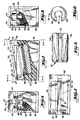
- Fig. 1 is a partially cut-away side plan view of a "normally closed” embodiment of a shutter mechanism of the present invention.
- Figs. 2-4 are respective front, rear and top plan views of the embodiment of Fig. 1.
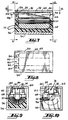
- Fig. 5 is a top plan view of a sliced cylindrical core of an electromagnet for shutter mechanisms of the present invention.
- Fig. 6 is an end view of the core of Fig. 5.
- Fig. 7 is a side sectional view of a "normally open” embodiment of a shutter mechanism of the present invention.
- Figs. 8-10 are respective top, front and rear plan views of the embodiment of Fig. 7.
- Fig. 11 is a side sectional view of a prior art shutter mechanism.
- a "normally closed" embodiment of a shutter mechanism of the present invention includes a flat elongated ferromagnetic blade 30 oriented at near grazing incidence in the path of an incoming light beam 32 from a laser source.
- the angle of incidence of light against the blade 30 is about 84 degrees with respect to the normal to the blade surface.
- Blade 30 may be coated with aluminum to further enhance reflectivity. For polarized light in the range from the near ultraviolet to the near infrared wavelengths, the reflectivity typically approaches 98%.
- the shutter also includes an electromagnet comprising a core 34 wrapped with a wire winding 36.
- Core 34 seen in isolation in Figs. 5 and 6, is a long cylinder with a lengthwise slice taken out, defining poles 38 and 40 with a channel gap 42 therebetween.
- the pole surfaces are machined to match the curvature of the blade's natural cantilever spring contour for the desired deflection.
- the core material is a magnetic grade iron with high permeability providing low hysteresis loss, and high efficiency.
- the winding 36 is wrapped toroidally, i.e. end-to-end around the core 34 so as to form a toroidal magnetic field when energized.
- Winding 36 communicates with an electrical power source via leads 44.
- Drive electronics not part of this invention, control the duty cycle and frequency of the electric power supplied to the electromagnet. Typically, a drive voltage of from 15 to 30 volts DC is used.
- Blade 30 is mounted flush against a backup plate 46.
- a blade retainer 48 secures the blade to backup plate 46 with screws 50.
- a lengthwise slot 52 is cut out of backup plate 46. Slot 52 coincides with the beam path 32, and is normally covered by blade 30.
- a wedge-shaped thermal tongue 54 is disposed between the poles 38 and 40 of the electromagnet. Tongue 54 is preferably made from copper for high heat conductivity, and is chemically blackened for light absorptance. Tongue 54 is attached at an end to blade retainer 48, and is oriented so that a top surface of the tongue is level with the surface of poles 38 and 40 and approximately parallel to beam path 32.
- blade 30 and the electromagnet made up of core 34 and windings 36 are in a V-shaped relationship with the blade 30 and backup plate 46 defining one leg of the "V” and the inactive poles 38 and 40 of the electromagnet and tongue 54 defining the other leg of the "V", the light beam path 32 passing between the two legs generally parallel to the poles 38 and 40 and tongue 54.
- the high reflectivity of the blade 30 allows the optical power to be dumped to the thermal tongue 54, from which the resulting heat is channeled via thermally conducting epoxy 58 to the shutter's exterior case 56.
- Case 56 is typically aluminum for high heat conductivity. Any thermal energy absorbed by the blade can be transferred to the backup plate 46 by direct contact.
- the blade 30 redirects the power and avoids temperatures which could change its spring temper.
- the heat from the magnetic winding 36 is channeled out via thermally conducting epoxy 58 inside the case 56 surrounding the electromagnet. Heat channeled to the case 56 can be handled by any of a variety of standard heat sink packages built around the case.
- the V-shaped arrangement of blade 30 relative to magnetic poles 38 and 40 and tongue 54 causes the shutter to act as a light trap in the normally closed position.
- the fact that the blade is mounted at an end opposite that of the light source, i.e. opposite from the input side of the shutter, together with the grazing incidence of the light path 32 with the blade 30, means that the blade 30 and tongue 54 cause multiple scatter reflections to be absorbed in the narrow "V", resulting in nearly zero backscatter to the optical source.
- Blade 30 traps beam power in the shutter as it intercepts the beam, so there is no stray reflection.
- the electromagnet attracts the blade 30 downward toward poles 38 and 40, as indicated by arrow 60 in Fig. 1.
- Blade 30 flexes out of the way of beam path 32, allowing the beam to pass through the cutout slot 52 in backup plate 46, as indicated by arrow 62 in Fig. 1.
- a thermal elastomer may be provided on poles 38 and 40 for cushioning the impact of the blade 30 against the poles.
- the poles 38 and 40 are machined to match the curvature of the blade's natural cantilever spring contour.
- the ferromagnetic blade 30 closes the magnetic circuit and becomes an essential part of the magnetics, making the toroidally wound cylindrical electromagnet extremely efficient and producing fast rise and fall times.
- the stiffness of blade 30 allows it to return quickly to the normal closed position once the power to the winding 36 has been shut off. Typically, a pulse repetition rate of up to 200 Hz can be achieved with optical rise and fall times of about 300 microseconds.
- the stiff retained blade combines with the contoured pole surface to give the blade a long lifetime exceeding one billion cycles.
- the straight through aperture provided by slot 52 has no optical elements or surfaces, and therefore does not alter the wavefront of coherent sources, such as lasers, when the shutter is open.
- a "normally open" embodiment of the shutter mechanism includes a flat elongated ferromagnetic blade 64 oriented approximately parallel to the path 66 of an incoming light beam from a source, such as a laser. Typically, blade 64 is coated with aluminum for high optical reflectivity.
- the shutter also includes an electromagnet including a core 68 and wire winding 70. Winding 70 communicates with an electrical power source via leads 72. Drive electronics, not part of this invention, control the duty cycle and frequency of the electric power supplied to the electromagnet.
- Core 68 is again a long cylinder with a lengthwise slice taken out.
- the slice defines poles 74 and 76 with a channel gap 78 therebetween.
- the core material is a magnetic grade iron with high permeability, and the core 68 is wrapped toroidally end-to-end by winding 70 so as to form a toroidal magnetic field when energized.
- the pole surfaces are machined to match the natural cantilever spring contour of the blade 64 when flexed.
- Blade 64 is mounted flush against a backup plate 80.
- a blade retainer 82 secures the blade 64 to backup plate 80 with screws 84.
- Backup plate 80 does not have a slot cutout, and is preferably made from copper for high thermal conductivity and chemically blackened for optical absorptance.
- Blade retainer 82 has a channel 86 defined therein coinciding with gap 78 between the electromagnetic poles 74 and 76 so as to provide an aperture for the light beam 88.
- blade 64 and the electromagnet are in a V-shaped relationship with the blade 64 and backup plate 80 defining one leg of the "V” and the inactive poles 74 and 76 of the electromagnet defining the other leg of the "V".
- the light beam path 66 and 88 passes between the two legs generally parallel to blade 64 through the gap 78 between poles 74 and 76 and through channel 86 of retainer 82.
- Blade 64 In operation, when the toroidal winding 70 is energized, the electromagnet attracts the blade 64 downward toward poles 74 and 76, as indicated by arrow 90 in Fig. 7. Blade 64 flexes into the beam path 66, trapping the beam. A thermal elastomer, not shown, may be provided on poles 74 and 76 for cushioning the impact of the blade 64 against the poles. Blade 64 completes the magnetic circuit of the cylindrical core 68, making the electromagnet highly efficient.
- the flexed blade 92 shown in phantom in Fig. 7, is oriented at a grazing angle of incidence, typically about 84° relative to the normal to the blade.
- the optical power is reflected by the blade 92 onto absorptive backup plate 80. Any thermal energy absorbed by the blade can be transferred to the magnetic poles 74 and 76 via the thermal elastomer, or conveyed through blade retainer 82 to the shutter's external casing 94. Heat from the magnetic winding 70 is channeled out via thermally conducting epoxy 96 to case 94.
- Flexed blade 92 and backup plate 80 form a narrow V-shaped light trap which prevents backscattering.
- Both normally open and normally closed embodiments can sink over 10 watts of optical power without affecting the performance of the blade.
- High speed modulation typically up to 200 Hz or higher, is achieved without backscatter or stray reflection. Long life of over 1 billion cycles is achieved because the stiff blade operates well below its cantilever spring elastic limit.
- the shutter is nonresonant and noninertial so as to allow rapid changes in duty cycle and frequency. The shutter is thus suitable for both high speed and high power laser pulse modulation.
Landscapes
- Physics & Mathematics (AREA)
- General Physics & Mathematics (AREA)
- Optics & Photonics (AREA)
- Mechanical Light Control Or Optical Switches (AREA)
- Shutters For Cameras (AREA)
- Lasers (AREA)
Claims (7)
- Ein Verschlußmechanismus zum Unterbrechen eines von einer Quelle längs eines Weges (32; 66, 88) gerichteten Laserstrahls mit:
einem flexiblen, ferromagnetischen Blatt (30; 64) zum Reflektieren des Laserstrahls und
einem Elektromagneten (34, 36; 68, 70), der mit einer elektrischen Energiequelle in Verbindung steht, wobei der Elektromagnet (34, 36; 68, 70) einen Kern (34; 68) und eine um den Kern (34; 68) gewickelte ringförmige Wicklung (36; 70) aufweist;
gekennzeichnet durch
eine Platte (46; 80), wobei das Blatt (30; 64) an einem Ende an der Platte (46; 80) befestigt ist und bündig mit der Platte (46; 80) ist, wenn der Elektromagnet (34, 36; 68, 70) ausgeschaltet ist, und durch
eine Einrichtung (54; 80) zum Absorbieren von von dem Blatt (30; 64) reflektierten Licht,
wobei der Kern (34; 68) ein Ringkern ist, von dem eine längsgerichtete Scheibe (42; 78) entfernt wurde, so daß zwei beabstandete Pole (38, 40; 74, 76) festgelegt werden, deren Polflächen an die normale Auslegerfeder-Kontur des freien Endes des flexiblen, ferromagnetischen Blatts (30; 64, 92) angepaßt sind, wenn der Elektromagnet (34, 36; 68, 70) aktiv ist, und wobei die Platte und die Polflächen der Pole (38, 40; 74, 76) unter Ausbildung einer engen V-förmigen Beziehung befestigt sind, so daß das Blatt (30; 64) den Laserstrahl zur Einrichtung (54; 80) zum Absorbieren von Licht reflektiert, wenn entweder das Blatt (30) bündig mit der Platte (46) ist oder wenn das Blatt (64) zu den Polen (74, 76) hingebogen ist. - Der Verschlußmechanismus nach Anspruch 1, wobei die Platte (46) einen darin befindlichen Schlitz (52) aufweist und wobei die Platte (46) so angeordnet ist, daß das Blatt zum Übertragen des Laserstrahls längs des Lichtweges (32) durch den Schlitz (52) den Schlitz (52) freilegt, wenn der Elektromagnet (34, 36) aktiv ist.
- Der Verschlußmechanismus nach irgendeinem vorhergehenden Anspruch, ferner aufweisend eine Einrichtung (48, 50, 56; 82, 96) zum Ableiten von Wärme von der absorbierenden Einrichtung (54; 80).
- Der Verschlußmechanismus nach Anspruch 1, wobei das Blatt (64) den Laserstrahl zu der Platte (80) reflektiert, die eine lichtabsorbierende Platte ist, wenn das Blatt (64) zu den Polen (74, 76) hingebogen ist.
- Der Verschlußmechanismus nach irgendeinem vorhergehenden Anspruch, ferner gekennzeichnet durch ein elastisches Polymer, das auf den Polen (38, 40; 74, 76) angeordnet ist.
- Der Verschlußmechanismus nach Anspruch 2 oder 3, wobei die absorbierende Einrichtung eine lichtabsorbierende Zunge (54) ist, die zwischen den Polen (38, 40) angeordnet ist.
- Der Verschlußmechanismus nach irgendeinem vorhergehenden Anspruch, wobei das Blatt (30; 64) mit einem lichtreflektierenden Material überzogen ist.
Applications Claiming Priority (3)
| Application Number | Priority Date | Filing Date | Title |
|---|---|---|---|
| US07/177,952 US4799767A (en) | 1988-04-05 | 1988-04-05 | High speed shutter for a laser beam |
| US177952 | 1988-04-05 | ||
| PCT/US1989/001101 WO1989009944A1 (en) | 1988-04-05 | 1989-03-17 | High speed shutter for a laser beam |
Publications (3)
| Publication Number | Publication Date |
|---|---|
| EP0408657A1 EP0408657A1 (de) | 1991-01-23 |
| EP0408657A4 EP0408657A4 (en) | 1991-11-21 |
| EP0408657B1 true EP0408657B1 (de) | 1995-02-01 |
Family
ID=22650590
Family Applications (1)
| Application Number | Title | Priority Date | Filing Date |
|---|---|---|---|
| EP89905250A Expired - Lifetime EP0408657B1 (de) | 1988-04-05 | 1989-03-17 | Hochgeschwindigkeitsverschluss für laserstrahl |
Country Status (7)
| Country | Link |
|---|---|
| US (1) | US4799767A (de) |
| EP (1) | EP0408657B1 (de) |
| JP (1) | JP2683836B2 (de) |
| CA (1) | CA1314739C (de) |
| DE (1) | DE68921000T2 (de) |
| IL (1) | IL89740A (de) |
| WO (1) | WO1989009944A1 (de) |
Cited By (2)
| Publication number | Priority date | Publication date | Assignee | Title |
|---|---|---|---|---|
| DE102012203310A1 (de) | 2012-03-02 | 2013-09-05 | Kuhnke Automation Gmbh & Co. Kg | Vorrichtung zum Unterbrechen eines Lichtstrahls, insbesondere Laserlichtstrahls |
| DE202014000042U1 (de) | 2014-01-08 | 2014-01-29 | Kendrion Kuhnke Automation Gmbh | Vorrichtung zum Unterbrechen eines Lichtstrahls, insbesondere Laserlichtstrahls |
Families Citing this family (15)
| Publication number | Priority date | Publication date | Assignee | Title |
|---|---|---|---|---|
| US4946256A (en) * | 1989-01-11 | 1990-08-07 | Nm Laser Products, Inc. | Right angle shutter for laser beam |
| US4995700A (en) * | 1989-03-31 | 1991-02-26 | The United States Of America As Represented By The Administrator Of The National Aeronautics And Space Administration | Cryogenic shutter |
| US5128796A (en) * | 1989-03-31 | 1992-07-07 | The United States Of America As Represented By The Administrator Of The National Aeronautics And Space Administration | Cryogenic shutter |
| US5033016A (en) * | 1990-03-06 | 1991-07-16 | The Boeing Company | Coherence multiplexed arithmetic/logic unit |
| US5032005A (en) * | 1990-04-24 | 1991-07-16 | Nm Laser Products, Inc. | High speed shutter mechanism for a light beam |
| FR2666159B1 (fr) * | 1990-08-22 | 1992-12-11 | Aerospatiale | Dispositif bistable sans frottement pour usage spatial, notamment pour l'obturation d'un orifice d'entree d'un instrument optique spatial. |
| US6542243B2 (en) | 2000-01-27 | 2003-04-01 | Lambda Physik Ag | Resonator optics monitoring method |
| US6587202B2 (en) | 2000-01-28 | 2003-07-01 | Lambda Physik Ag | Optical materials testing method |
| US6775315B1 (en) * | 2001-06-08 | 2004-08-10 | Scott Allen Nield | Apparatus and method of directing a laser beam to a thermally managed beam dump in a laser system |
| US6796710B2 (en) * | 2001-06-08 | 2004-09-28 | Ethicon Endo-Surgery, Inc. | System and method of measuring and controlling temperature of optical fiber tip in a laser system |
| US6995359B1 (en) | 2003-06-11 | 2006-02-07 | The United States Of America As Represented By The Secretary Of The Navy | Miniature cryogenic shutter assembly |
| JP3734812B2 (ja) * | 2003-11-04 | 2006-01-11 | 浜松ホトニクス株式会社 | シャッタユニット及びそれを用いたレーザ加工装置 |
| US8585956B1 (en) | 2009-10-23 | 2013-11-19 | Therma-Tru, Inc. | Systems and methods for laser marking work pieces |
| US10018830B1 (en) | 2015-02-09 | 2018-07-10 | Dachwood Physik, Inc. | High damage threshold broadband laser shutter |
| US12007552B2 (en) | 2020-04-24 | 2024-06-11 | University Of Rochester | Fail safe beam shutter devices and systems |
Family Cites Families (11)
| Publication number | Priority date | Publication date | Assignee | Title |
|---|---|---|---|---|
| US3553364A (en) * | 1968-03-15 | 1971-01-05 | Texas Instruments Inc | Electromechanical light valve |
| US3619037A (en) * | 1968-09-19 | 1971-11-09 | Trw Inc | A laser beam shutter including a heat sink |
| US4202602A (en) * | 1973-12-03 | 1980-05-13 | Ismael Torres | Multi-angular radiant energy modulator |
| US4082435A (en) * | 1976-01-07 | 1978-04-04 | Johnson & Johnson | Optical switch |
| US4070099A (en) * | 1976-04-22 | 1978-01-24 | The United States Of America As Represented By The Secretary Of The Army | Fast shutter mechanism for high power thermal radiation |
| US4103261A (en) * | 1976-06-25 | 1978-07-25 | Duncan Electric Company, Inc. | Laser beam shutter and beam indicator |
| US4208103A (en) * | 1977-09-01 | 1980-06-17 | Dielectric Systems International | Electrostatic display device |
| US4257017A (en) * | 1978-07-11 | 1981-03-17 | The United States Of America As Represented By The United States Department Of Energy | Post pulse shutter for laser amplifier |
| DE3031908C2 (de) * | 1980-08-23 | 1982-05-27 | Messerschmitt-Bölkow-Blohm GmbH, 8000 München | Strahlenschalter |
| US4332450A (en) * | 1980-09-15 | 1982-06-01 | James Dole Corporation | Magnetic actuation methods and apparatus |
| DE3447316C1 (de) * | 1984-12-24 | 1986-02-13 | Dornier System Gmbh, 7990 Friedrichshafen | Vorrichtung zum Unterbrechen eines Laserstrahls |
-
1988
- 1988-04-05 US US07/177,952 patent/US4799767A/en not_active Expired - Lifetime
-
1989
- 1989-03-17 EP EP89905250A patent/EP0408657B1/de not_active Expired - Lifetime
- 1989-03-17 WO PCT/US1989/001101 patent/WO1989009944A1/en not_active Ceased
- 1989-03-17 JP JP1504983A patent/JP2683836B2/ja not_active Expired - Fee Related
- 1989-03-17 DE DE68921000T patent/DE68921000T2/de not_active Expired - Fee Related
- 1989-03-24 IL IL89740A patent/IL89740A/xx not_active IP Right Cessation
- 1989-04-04 CA CA000595615A patent/CA1314739C/en not_active Expired - Fee Related
Cited By (2)
| Publication number | Priority date | Publication date | Assignee | Title |
|---|---|---|---|---|
| DE102012203310A1 (de) | 2012-03-02 | 2013-09-05 | Kuhnke Automation Gmbh & Co. Kg | Vorrichtung zum Unterbrechen eines Lichtstrahls, insbesondere Laserlichtstrahls |
| DE202014000042U1 (de) | 2014-01-08 | 2014-01-29 | Kendrion Kuhnke Automation Gmbh | Vorrichtung zum Unterbrechen eines Lichtstrahls, insbesondere Laserlichtstrahls |
Also Published As
| Publication number | Publication date |
|---|---|
| JP2683836B2 (ja) | 1997-12-03 |
| JPH03503686A (ja) | 1991-08-15 |
| US4799767A (en) | 1989-01-24 |
| IL89740A0 (en) | 1989-09-28 |
| DE68921000T2 (de) | 1995-10-19 |
| IL89740A (en) | 1992-03-29 |
| DE68921000D1 (de) | 1995-03-16 |
| WO1989009944A1 (en) | 1989-10-19 |
| CA1314739C (en) | 1993-03-23 |
| EP0408657A1 (de) | 1991-01-23 |
| EP0408657A4 (en) | 1991-11-21 |
Similar Documents
| Publication | Publication Date | Title |
|---|---|---|
| EP0408657B1 (de) | Hochgeschwindigkeitsverschluss für laserstrahl | |
| US4946256A (en) | Right angle shutter for laser beam | |
| US5221987A (en) | FTIR modulator | |
| GB2253515A (en) | Laser device | |
| US5032005A (en) | High speed shutter mechanism for a light beam | |
| JP2005513791A (ja) | 特に波長可変レーザのための再帰反射デバイス | |
| JPH03135082A (ja) | 集積レーザダイオードポンプレーザ装置 | |
| JP3325585B2 (ja) | ファイバレーザの出射部でポンピング光を低減する方法およびファイバレーザ装置 | |
| WO2005098483A1 (en) | Aperture stop assembly for high power laser beams | |
| EP0615145A1 (de) | Anordnung eines optischen Isolators, welche die Verkippung der optischen Achse aufgrund von Klebstoff-Verformung verhindert | |
| US6836610B2 (en) | Electrical variable optical attenuator | |
| US5018150A (en) | Reflector switched lasers | |
| US3504295A (en) | Optically clad laser | |
| JP4491064B2 (ja) | 光路変更装置、光スイッチ及び光ヘッド | |
| EP4094114B1 (de) | Optischer begrenzer und verfahren zur begrenzung des strahlungsflusses | |
| US4688076A (en) | Noise reducing heat sink for semiconductor laser diodes | |
| JPH0728589Y2 (ja) | 光ピツクアツプ | |
| JPH02216881A (ja) | 外部共振型半導体レーザ装置 | |
| JP4325036B2 (ja) | アパーチャ | |
| JP3275557B2 (ja) | 温度検出装置 | |
| EP3889665A1 (de) | Optischer begrenzer und verfahren zur begrenzung des strahlungsflusses | |
| JPS6473692A (en) | Laser light source | |
| JPH0740072A (ja) | レーザ加工用エネルギー分割装置 | |
| JPH1138332A (ja) | レーザ光の光量調整装置 | |
| GB2593873A (en) | Optical limiter and method for limiting radiant flux |
Legal Events
| Date | Code | Title | Description |
|---|---|---|---|
| PUAI | Public reference made under article 153(3) epc to a published international application that has entered the european phase |
Free format text: ORIGINAL CODE: 0009012 |
|
| 17P | Request for examination filed |
Effective date: 19900925 |
|
| AK | Designated contracting states |
Kind code of ref document: A1 Designated state(s): DE FR GB IT |
|
| A4 | Supplementary search report drawn up and despatched |
Effective date: 19910927 |
|
| AK | Designated contracting states |
Kind code of ref document: A4 Designated state(s): DE FR GB IT |
|
| 17Q | First examination report despatched |
Effective date: 19930826 |
|
| GRAA | (expected) grant |
Free format text: ORIGINAL CODE: 0009210 |
|
| AK | Designated contracting states |
Kind code of ref document: B1 Designated state(s): DE FR GB IT |
|
| REF | Corresponds to: |
Ref document number: 68921000 Country of ref document: DE Date of ref document: 19950316 |
|
| ITF | It: translation for a ep patent filed | ||
| ET | Fr: translation filed | ||
| PLBE | No opposition filed within time limit |
Free format text: ORIGINAL CODE: 0009261 |
|
| STAA | Information on the status of an ep patent application or granted ep patent |
Free format text: STATUS: NO OPPOSITION FILED WITHIN TIME LIMIT |
|
| 26N | No opposition filed | ||
| PGFP | Annual fee paid to national office [announced via postgrant information from national office to epo] |
Ref country code: GB Payment date: 20010309 Year of fee payment: 13 |
|
| REG | Reference to a national code |
Ref country code: GB Ref legal event code: IF02 |
|
| PG25 | Lapsed in a contracting state [announced via postgrant information from national office to epo] |
Ref country code: GB Free format text: LAPSE BECAUSE OF NON-PAYMENT OF DUE FEES Effective date: 20020317 |
|
| GBPC | Gb: european patent ceased through non-payment of renewal fee |
Effective date: 20020317 |
|
| PGFP | Annual fee paid to national office [announced via postgrant information from national office to epo] |
Ref country code: FR Payment date: 20040325 Year of fee payment: 16 |
|
| PG25 | Lapsed in a contracting state [announced via postgrant information from national office to epo] |
Ref country code: IT Free format text: LAPSE BECAUSE OF NON-PAYMENT OF DUE FEES;WARNING: LAPSES OF ITALIAN PATENTS WITH EFFECTIVE DATE BEFORE 2007 MAY HAVE OCCURRED AT ANY TIME BEFORE 2007. THE CORRECT EFFECTIVE DATE MAY BE DIFFERENT FROM THE ONE RECORDED. Effective date: 20050317 |
|
| PG25 | Lapsed in a contracting state [announced via postgrant information from national office to epo] |
Ref country code: FR Free format text: LAPSE BECAUSE OF NON-PAYMENT OF DUE FEES Effective date: 20051130 |
|
| REG | Reference to a national code |
Ref country code: FR Ref legal event code: ST Effective date: 20051130 |
|
| PGFP | Annual fee paid to national office [announced via postgrant information from national office to epo] |
Ref country code: DE Payment date: 20060331 Year of fee payment: 18 |
|
| PG25 | Lapsed in a contracting state [announced via postgrant information from national office to epo] |
Ref country code: DE Free format text: LAPSE BECAUSE OF NON-PAYMENT OF DUE FEES Effective date: 20071002 |