EP0408954A2 - Tube à décharge rempli de gaz - Google Patents
Tube à décharge rempli de gaz Download PDFInfo
- Publication number
- EP0408954A2 EP0408954A2 EP90112497A EP90112497A EP0408954A2 EP 0408954 A2 EP0408954 A2 EP 0408954A2 EP 90112497 A EP90112497 A EP 90112497A EP 90112497 A EP90112497 A EP 90112497A EP 0408954 A2 EP0408954 A2 EP 0408954A2
- Authority
- EP
- European Patent Office
- Prior art keywords
- gas
- discharge
- tube
- filled
- voltage
- Prior art date
- Legal status (The legal status is an assumption and is not a legal conclusion. Google has not performed a legal analysis and makes no representation as to the accuracy of the status listed.)
- Withdrawn
Links
Images
Classifications
-
- H—ELECTRICITY
- H01—ELECTRIC ELEMENTS
- H01T—SPARK GAPS; OVERVOLTAGE ARRESTERS USING SPARK GAPS; SPARKING PLUGS; CORONA DEVICES; GENERATING IONS TO BE INTRODUCED INTO NON-ENCLOSED GASES
- H01T1/00—Details of spark gaps
-
- H—ELECTRICITY
- H01—ELECTRIC ELEMENTS
- H01J—ELECTRIC DISCHARGE TUBES OR DISCHARGE LAMPS
- H01J17/00—Gas-filled discharge tubes with solid cathode
- H01J17/02—Details
- H01J17/04—Electrodes; Screens
-
- H—ELECTRICITY
- H01—ELECTRIC ELEMENTS
- H01J—ELECTRIC DISCHARGE TUBES OR DISCHARGE LAMPS
- H01J17/00—Gas-filled discharge tubes with solid cathode
- H01J17/38—Cold-cathode tubes
- H01J17/40—Cold-cathode tubes with one cathode and one anode, e.g. glow tubes, tuning-indicator glow tubes, voltage-stabiliser tubes, voltage-indicator tubes
Definitions
- the present invention relates to a discharge tube for voltage control and, more specifically, to a gas-filled discharge tube for operation as the series gap of the ignition system of an automotive spark-ignition engine.
- the ignition system of an automotive spark-ignition engine applies a high voltage across the electrodes of a spark plug to pass an electrical discharge between the electrodes.
- a previously proposed ignition system of a series gap type employs a discharge gap connected in series to a spark plug to control the ignition timing accurately and prevent the smoking of the explosive mixture.
- Such an ignition system of a series gap type employs a gas-filled discharge tube comprising a tube filled with an inert gas, and electrodes provided respectively at the opposite ends of the tube.
- the accurate control of the spark timing by using the gas-filled discharge tube serving as a series gap requires a discharge inception voltage of the discharge tube higher than that of the spark plug, for example, the former not lower than 10 KV.
- the discharge inception voltage of the tube can be increased by increasing the distance between the electrodes or by increasing the pressure of the inert gas filling the tube.
- a measure for increasing the discharge inception voltage entails unstable discharge inception voltage and requires a comparatively high discharge sustaining voltage, which increases energy loss and affects adversely to the reliability of the igniting function of the spark plug.
- a gas-filled discharge tube comprises an electrically insulating tube filled with a pressurized gas, and a pair of electrodes provided opposite to each other within the electrically insulating tube.
- the opposite surfaces of the discharge electrodes are formed substantially in a flat surface, the electrodes have no sharp edge, and the gas filling the electrically insulating tube is argon gas, nitrogen gas or a mixed gas of argon gas and nitrogen gas.
- the substantially flat opposite surfaces of the gas-filled discharge tube prevents local discharges. Since the electrodes have no sharp edges and the electrically insulating tube is filled with an inert gas, such as argon, nitrogen or a mixed gas of argon and nitrogen, the surfaces of the electrodes are less susceptible to deterioration and a stable discharge can be sustained.
- an inert gas such as argon, nitrogen or a mixed gas of argon and nitrogen
- the pressure of the gas not lower than 5 atm and the product of the diameter of the electrodes and the distance between the electrodes not greater than 20 mm2 stabilize the discharge inception voltage still further.
- a mixed gas containing 50% by volume or less nitrogen and 50% or more argon by volume reduces the discharge sustaining voltage to a comparatively low level without decreasing the discharge inception voltage.
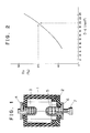
- a gas-filled discharge tube in a preferred embodiment according to the present invention comprises a tube 1 formed of an electrically insulating material such as a ceramic, an end cap 2 formed of the same material as that forming the tube 1, a first discharge electrode 3 having a longitudinal section resembling the shape of the letter U, having a substantially flat top surface, formed of a perforated metallic plate and inserted in the tube 1 through an opening formed in the top wall of the tube 1, a first terminal 4 connected to the first discharge electrode 3, a second discharge electrode 5 of the substantially same construction as that of the first discharge electrode 3 and inserted in the tube 1 through an opening formed in the end cap 2, a second terminal 6 connected to the second discharge electrode 5, and a gas-charging pipe 7 combined with the second terminal 6.
- an electrically insulating material such as a ceramic
- an end cap 2 formed of the same material as that forming the tube 1
- a first discharge electrode 3 having a longitudinal section resembling the shape of the letter U, having a substantially flat top surface
- the first discharge electrode 3 is fixed together with the first electrode 4 to the top wall of the tube 1 with glass or a metallic solder so as to seal the gap between the first electrode 3 and the opening of the top wall of the tube 1
- the second discharge electrode 5 is fixed to the end cap 2 with glass or a metallic solder so as to seal the gap between the second discharge electrode 5 and the opening of the end cap 2.
- the gas-charging pipe 7 is sealed by crushing and soldering after charging the assembly of the tube 1, the cap 2 and the electrodes 3 and 5 with a pressurized gas.
- the gas-filled discharge tube thus constructed employs argon gas, nitrogen gas or a mixed gas of argon gas and nitrogen gas for filling the tube 1 and is capable of stably and satisfactorily operating for a long duration of service at a high discharge inception voltage of 10 KV or higher.
- the discharge inception voltage can readily be increased up to such a high voltage, for example, 15 KV, by increasing the gas pressure as proposed previously.
- an inert gas such as argon or helium
- the pressure of the inert gas must be very high to make the gas-filled discharge tube operate at a sufficiently high discharge inception voltage.
- the increased voltage by increasing the pressure of the inert gas filling the tube of the gas-filled discharge tube is liable to fluctuate unavoidably in a certain range under some operating condition.
- the fluctuation in the voltage can effectively suppressed when the pressure of the gas filling the tube, such as argon, nitrogen or a mixed gas of argon and nitrogen, is 5 atm or higher and the product of the diameter of the discharge electrodes and the distance between the discharge electrodes is 20 mm2 or less.
- a pressure of the gas lower than 5 atm makes discharging position on the opposite surfaces of the discharge electrodes unsteady, makes discharges liable to pass between the side surfaces of the discharge electrodes and is unable to suppress the fluctuation in the discharge inception voltage.
- the reduction of the product of the diameter of the discharge electrodes and the distance between the discharge electrodes reduces the fluctuation in the discharge inception voltage very effectively.
- Test gas-filled discharge tubes of the construction shown in Fig. 1 respectively having pairs of discharge electrodes differing from each other in the diameter D (mm) of the discharge electrodes and the distance d (mm) between the discharge electrodes and filled respectively with mixed argon-nitrogen gases of different compositions so that the discharge inception voltage is 15 KV were fabricated.
- the test gas-filled discharge tubes were subjected to repetitive discharge tests to determine the range R v (%) of variation of the discharge inception voltage. Test results are shown in Fig. 2. As is obvious from Fig.
- the product D ⁇ d of the diameter D of the discharge electrodes and the distance d between the discharge electrodes must be 20 mm2 or less to restrict the discharge inception voltage to a range of 15 ⁇ 1.5 KV, namely, to restrict the range of variation of the voltage to 20% or below.
- the increased discharge inception voltage causes unfavorably high discharge sustaining voltage. It is to be desired that this discharge sustaining voltage should be maintained as low as possible, with high discharge inception voltage, for example, 15 kV.
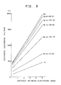
- Test gas-filled discharge tubes of the construction shown in Fig. 1 respectively having pairs of discharge electrodes differing from each other in the distance d (mm) between the discharge electrodes and filled respectively with gases of different compositions so that the discharge inception voltage is 15 KV were fabricated. These test gas-filled discharge tubes were tested for the discharge sustaining voltages. Test results are shown in Fig. 3. As is obvious from Fig. 3, the discharge sustaining voltage v varies linearly with the distance d (mm) between the discharge electrodes, the discharge sustaining voltage varies in a comparatively narrow range when the nitrogen content of the gas is higher than 50% by volume, and the discharge sustaining voltage drops sharply when the nitrogen content of the gas is 50% by volume or below and the argon content of the same is 50% by volume or above.
- a pressure of 5 atm or above of the gas filling the gas-filled discharge tube and the product of the diameter of the discharge electrodes and the distance between the discharge electrodes of 20 mm2 or above are preferable to reduce the range of variation of the discharge inception voltage, maintaining the voltage at a high level.
- a composition of the gas filling the gas-filled discharge tube of 50% by volume or below nitrogen content and 50% by volume or above argon content is preferable to reduce the discharge sustaining voltage maintaining the discharge inception voltage at a high level.
Landscapes
- Gas-Filled Discharge Tubes (AREA)
- Discharge Lamp (AREA)
- Spark Plugs (AREA)
Applications Claiming Priority (2)
| Application Number | Priority Date | Filing Date | Title |
|---|---|---|---|
| JP184516/89 | 1989-07-19 | ||
| JP1184516A JPH0353481A (ja) | 1989-07-19 | 1989-07-19 | 放電管 |
Publications (2)
| Publication Number | Publication Date |
|---|---|
| EP0408954A2 true EP0408954A2 (fr) | 1991-01-23 |
| EP0408954A3 EP0408954A3 (en) | 1991-05-15 |
Family
ID=16154566
Family Applications (1)
| Application Number | Title | Priority Date | Filing Date |
|---|---|---|---|
| EP19900112497 Withdrawn EP0408954A3 (en) | 1989-07-19 | 1990-06-29 | Gas-filled discharge tube |
Country Status (4)
| Country | Link |
|---|---|
| US (1) | US5185556A (fr) |
| EP (1) | EP0408954A3 (fr) |
| JP (1) | JPH0353481A (fr) |
| CA (1) | CA2019604C (fr) |
Cited By (3)
| Publication number | Priority date | Publication date | Assignee | Title |
|---|---|---|---|---|
| EP0507330A3 (en) * | 1991-04-05 | 1992-11-19 | Yazaki Corporation | A gas-filled discharge tube |
| DE4313619A1 (de) * | 1992-04-27 | 1993-10-28 | Yazaki Corp | Entladungsröhre |
| US5352953A (en) * | 1991-04-05 | 1994-10-04 | Yazaki Corporation | Gas-filled discharge tube |
Families Citing this family (4)
| Publication number | Priority date | Publication date | Assignee | Title |
|---|---|---|---|---|
| JPH0785840A (ja) * | 1993-09-20 | 1995-03-31 | Yazaki Corp | ガス入り放電管 |
| US5686789A (en) * | 1995-03-14 | 1997-11-11 | Osram Sylvania Inc. | Discharge device having cathode with micro hollow array |
| CN101752794B (zh) * | 2010-01-29 | 2012-07-18 | 安徽华东光电技术研究所 | 点火放电管着火电压的一致性和稳定性的控制方法 |
| KR20160029985A (ko) * | 2014-09-05 | 2016-03-16 | 성균관대학교산학협력단 | 유전체에 균일하게 플라즈마를 발생시키는 방법 |
Family Cites Families (13)
| Publication number | Priority date | Publication date | Assignee | Title |
|---|---|---|---|---|
| FR844089A (fr) * | 1937-09-29 | 1939-07-18 | Lampes Sa | Perfectionnements aux lampes à décharge |
| GB512286A (en) * | 1938-07-29 | 1939-08-31 | Gen Electric Co Ltd | Improvements in high-pressure metal-vapour electric discharge devices |
| US2457102A (en) * | 1941-02-17 | 1948-12-21 | Mini Of Supply | Spark gap |
| FR885734A (fr) * | 1941-09-11 | 1943-09-23 | Patent Treuhand Ges Fu R Elek | Lampe électrique à décharge gazeuse à haute pression |
| US2682007A (en) * | 1951-01-11 | 1954-06-22 | Hanovia Chemical & Mfg Co | Compact type electrical discharge device |
| GB745736A (en) * | 1951-11-29 | 1956-02-29 | British Thomson Houston Co Ltd | Improvements in and relating to electric discharge lamps |
| US3119040A (en) * | 1960-03-21 | 1964-01-21 | Gen Electric | Gas discharge gap tube |
| CH435460A (de) * | 1963-01-11 | 1967-05-15 | Zentralinstitut Fuer Kernphysi | Gasentladungsdiode |
| CH537521A (de) * | 1970-11-16 | 1973-05-31 | Bosch Gmbh Robert | Spulenzündanlage zum Betrieb von Brennkraftmaschinen mit mindestens einer auf ihrer Hochspannungsseite eingeschalteten Vorfunkenstrecke |
| US3956657A (en) * | 1972-07-18 | 1976-05-11 | Robert Bosch G.M.B.H. | Pre-ignition gap |
| DE2418261B2 (de) * | 1974-04-16 | 1976-05-13 | Siemens AG, 1000 Berlin und 8000 München | Funkenstreckenbauelement fuer zuendanlagen von brennkaftmaschinen |
| JPS55104092A (en) * | 1979-02-02 | 1980-08-09 | Tokyo Shibaura Electric Co | Discharge switching element |
| NL185478C (nl) * | 1980-09-05 | 1990-04-17 | Philips Nv | Hogedruknatriumdampontladingslamp. |
-
1989
- 1989-07-19 JP JP1184516A patent/JPH0353481A/ja active Pending
-
1990
- 1990-06-22 US US07/542,223 patent/US5185556A/en not_active Expired - Lifetime
- 1990-06-22 CA CA002019604A patent/CA2019604C/fr not_active Expired - Fee Related
- 1990-06-29 EP EP19900112497 patent/EP0408954A3/en not_active Withdrawn
Cited By (4)
| Publication number | Priority date | Publication date | Assignee | Title |
|---|---|---|---|---|
| EP0507330A3 (en) * | 1991-04-05 | 1992-11-19 | Yazaki Corporation | A gas-filled discharge tube |
| US5352953A (en) * | 1991-04-05 | 1994-10-04 | Yazaki Corporation | Gas-filled discharge tube |
| DE4313619A1 (de) * | 1992-04-27 | 1993-10-28 | Yazaki Corp | Entladungsröhre |
| DE4313619C2 (de) * | 1992-04-27 | 1998-07-30 | Yazaki Corp | Entladungsröhre |
Also Published As
| Publication number | Publication date |
|---|---|
| EP0408954A3 (en) | 1991-05-15 |
| US5185556A (en) | 1993-02-09 |
| JPH0353481A (ja) | 1991-03-07 |
| CA2019604A1 (fr) | 1991-01-19 |
| CA2019604C (fr) | 1994-03-01 |
Similar Documents
| Publication | Publication Date | Title |
|---|---|---|
| US5811933A (en) | High-pressure discharge lamp | |
| US3588576A (en) | Spark-gap device having a thin conductive layer for stabilizing operation | |
| US3989985A (en) | Surge voltage arrester | |
| US5185556A (en) | Gas-filled discharge tube | |
| US4604554A (en) | Triggered spark gap discharger | |
| US4198590A (en) | High current triggered spark gap | |
| US3906273A (en) | Two electrode spark gap apparatus | |
| EP0131922A1 (fr) | Dispositif électrique employant un diélectrique gazeux | |
| US4439708A (en) | Spark plug having dual gaps | |
| US6362945B1 (en) | Gas-filled surge arrester wIth an activating compound formed of a plurality of components | |
| KR0140089B1 (ko) | 광물질 첨가제를 함유하는 가스피뢰기 | |
| US5347532A (en) | Laser having at least one anode and one cathode for preionization and/or discharge | |
| RU2096855C1 (ru) | Газонаполненный разрядник | |
| EP0466106A1 (fr) | Tube à décharge | |
| USH60H (en) | Long-life triggered spark gap | |
| JPH10335042A (ja) | 放電管 | |
| US5473220A (en) | Discharge tube | |
| EP0407837A2 (fr) | Tube à décharge rempli de gaz | |
| US3187215A (en) | Spark gap device | |
| JPS63502232A (ja) | 内燃機関の点火プラグの特に予備火花ギヤップとして使用のための火花ギヤップ | |
| JP2745393B2 (ja) | 放電型サージ吸収素子 | |
| EP0769832A1 (fr) | Tube de decharge a surface de decharge revetue | |
| JPS61135041A (ja) | 電圧を増大させた低圧アーク放電ランプ | |
| US2654044A (en) | Electric discharge tube | |
| US4939418A (en) | Gas mixture for triggerable spark gaps |
Legal Events
| Date | Code | Title | Description |
|---|---|---|---|
| PUAI | Public reference made under article 153(3) epc to a published international application that has entered the european phase |
Free format text: ORIGINAL CODE: 0009012 |
|
| AK | Designated contracting states |
Kind code of ref document: A2 Designated state(s): DE GB |
|
| PUAL | Search report despatched |
Free format text: ORIGINAL CODE: 0009013 |
|
| AK | Designated contracting states |
Kind code of ref document: A3 Designated state(s): DE GB |
|
| 17P | Request for examination filed |
Effective date: 19910703 |
|
| 17Q | First examination report despatched |
Effective date: 19930802 |
|
| STAA | Information on the status of an ep patent application or granted ep patent |
Free format text: STATUS: THE APPLICATION IS DEEMED TO BE WITHDRAWN |
|
| 18D | Application deemed to be withdrawn |
Effective date: 19940906 |