EP0409088B1 - Assemblage de convertisseur de couple avec embrayage de dérivation actif en inverse - Google Patents
Assemblage de convertisseur de couple avec embrayage de dérivation actif en inverse Download PDFInfo
- Publication number
- EP0409088B1 EP0409088B1 EP90113369A EP90113369A EP0409088B1 EP 0409088 B1 EP0409088 B1 EP 0409088B1 EP 90113369 A EP90113369 A EP 90113369A EP 90113369 A EP90113369 A EP 90113369A EP 0409088 B1 EP0409088 B1 EP 0409088B1
- Authority
- EP
- European Patent Office
- Prior art keywords
- cylinder member
- turbine
- clutch
- annular
- torque converter
- Prior art date
- Legal status (The legal status is an assumption and is not a legal conclusion. Google has not performed a legal analysis and makes no representation as to the accuracy of the status listed.)
- Expired - Lifetime
Links
Images
Classifications
-
- F—MECHANICAL ENGINEERING; LIGHTING; HEATING; WEAPONS; BLASTING
- F16—ENGINEERING ELEMENTS AND UNITS; GENERAL MEASURES FOR PRODUCING AND MAINTAINING EFFECTIVE FUNCTIONING OF MACHINES OR INSTALLATIONS; THERMAL INSULATION IN GENERAL
- F16H—GEARING
- F16H45/00—Combinations of fluid gearings for conveying rotary motion with couplings or clutches
- F16H45/02—Combinations of fluid gearings for conveying rotary motion with couplings or clutches with mechanical clutches for bridging a fluid gearing of the hydrokinetic type
-
- F—MECHANICAL ENGINEERING; LIGHTING; HEATING; WEAPONS; BLASTING
- F16—ENGINEERING ELEMENTS AND UNITS; GENERAL MEASURES FOR PRODUCING AND MAINTAINING EFFECTIVE FUNCTIONING OF MACHINES OR INSTALLATIONS; THERMAL INSULATION IN GENERAL
- F16H—GEARING
- F16H45/00—Combinations of fluid gearings for conveying rotary motion with couplings or clutches
- F16H45/02—Combinations of fluid gearings for conveying rotary motion with couplings or clutches with mechanical clutches for bridging a fluid gearing of the hydrokinetic type
- F16H2045/021—Combinations of fluid gearings for conveying rotary motion with couplings or clutches with mechanical clutches for bridging a fluid gearing of the hydrokinetic type three chamber system, i.e. comprising a separated, closed chamber specially adapted for actuating a lock-up clutch
-
- F—MECHANICAL ENGINEERING; LIGHTING; HEATING; WEAPONS; BLASTING
- F16—ENGINEERING ELEMENTS AND UNITS; GENERAL MEASURES FOR PRODUCING AND MAINTAINING EFFECTIVE FUNCTIONING OF MACHINES OR INSTALLATIONS; THERMAL INSULATION IN GENERAL
- F16H—GEARING
- F16H45/00—Combinations of fluid gearings for conveying rotary motion with couplings or clutches
- F16H45/02—Combinations of fluid gearings for conveying rotary motion with couplings or clutches with mechanical clutches for bridging a fluid gearing of the hydrokinetic type
- F16H2045/0273—Combinations of fluid gearings for conveying rotary motion with couplings or clutches with mechanical clutches for bridging a fluid gearing of the hydrokinetic type characterised by the type of the friction surface of the lock-up clutch
- F16H2045/0278—Combinations of fluid gearings for conveying rotary motion with couplings or clutches with mechanical clutches for bridging a fluid gearing of the hydrokinetic type characterised by the type of the friction surface of the lock-up clutch comprising only two co-acting friction surfaces
Definitions
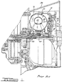
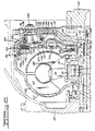
- a damper assembly is used to connect drivably an outward radial portion of the piston plate to the turbine hub.
- Converter turbine 80 includes an outer shroud 82 and radial inflow blades.
- the radially inward margin of the shroud 82 is secured to turbine hub 84, which is splined at 86 to turbine sleeve shaft 88.
- Turbine shaft 88 and the drive shaft for the pump define an annular flow passage 106 which communicates with the control pressure cavity 108 through porting formed in the hub 102.
- the pressure cavity 108 is defined by the inner surface of the wall 46 and the cylinder 90.
- An annular piston 116 is formed, preferably, by a stamping operation. It is provided with an axially extending first portion 118 which is in sliding and sealing engagement with surface 94 and a second axially extending portion 120 which is in sliding and sealing engagement with surface 96.
- the fluid that circulates through the torus circuit comes in direct contact with the clutch disc and the clutch plate, thereby providing adequate cooling during operation. It is possible to control the magnitude of the pressure in the working chamber 112 to effect a continuous slipping of the clutch, thereby damping torsional vibrations and transient engine torque changes during operation. The heat that is generated by the slipping of the clutch or by repeated application and release of the clutch is adequately dissipated in the fluid that is circulated through the torus circuit.
- That circuit includes a flow passage 136 formed in the stator sleeve shaft 60.
- the turbine hub can be ported, as shown at 138, to provide a torus circuit feed. Fluid is returned radially inward through port 139 formed in the impeller hub and in the stator hub. It then is returned to the transmission oil cooler through another passage, not shown.
- the clutch may be controlled more effectively with less transient capacity variation.
Landscapes
- Engineering & Computer Science (AREA)
- General Engineering & Computer Science (AREA)
- Mechanical Engineering (AREA)
- Hydraulic Clutches, Magnetic Clutches, Fluid Clutches, And Fluid Joints (AREA)
- Control Of Fluid Gearings (AREA)
- Mechanical Operated Clutches (AREA)
Claims (3)
- Convertisseur de couple hydrocinétique et ensemble d'embrayage à verrouillage pour utilisation avec un mécanisme de transmission de puissance prévu pour délivrer le couple à partir d'un arbre d'entraînement (54) à un arbre mené (88) comprenant :
un logement de convertisseur de couple (44, 46) ayant une cavité de convertisseur fermée, ladite cavité enfermant un rotor à aube (60) et une turbine à aube (80) disposés en relation d'écoulement de fluide toroïdal, ladite turbine étant placée à l'intérieur de ladite cavité entre ledit arbre d'entraînement (54) et ledit rotor (60),
ladite turbine (80) comportant un moyeu de turbine (84) accouplé audit arbre mené (88),
un élément de cylindre (90) fixé audit logement (44, 46) s'étendant radialement par rapport audit moyeu de la turbine (84) dans un emplacement radialement vers l'extérieur à l'intérieur de ladite cavité du convertisseur, des disques de frottement (124, 126) d'un embrayage à verrouillage fixé audit élément de cylindre audit emplacement extérieur, ledit élément de cylindre ayant des surfaces annulaires radialement espacées (94, 96) s'étendant axialement,
un piston annulaire (116) comportant des parties s'étendant axialement (118, 120) définissant des surfaces annulaires en alignement avec lesdites surfaces annulaires (94, 96) dudit élément de cylindre (90), ledit élément de cylindre et ledit piston définissant une chambre de pression (112),
un passage de distribution de pression (106, 108, 110, 114) s'étendant à partir de l'emplacement radialement vers l'extérieur contigu audit moyeu de la turbine (84) et défini par ledit élément de cylindre (90) et la paroi intérieure dudit logement (44, 46), ledit passage de distribution étant en communication avec ladite chambre de pression (112), et
un disque d'embrayage d'entraînement (128, 131) disposé contigu audit disque de frottement (124, 126) et accouplé audit arbre mené (88) d'où il résulte que ledit rotor (60) et ladite turbine (80) sont verrouillés ensemble lorsque ladite chambre de pression (112) est mise sous pression, caractérisé en ce que
lesdits disques frottement (124, 126) sont fixés à une partie (122) dudit élément de cylindre (90) qui est commun aux parties qui définissent ladite chambre de pression (112) et ledit passage de distribution de pression (106, 108, 110, 114),
lesdites surfaces annulaires (94, 96) dudit élément de cylindre (90) comprennent des surfaces radialement vers l'intérieur en regard par rapport audit arbre mené (88) et lesdites surfaces annulaires dudit piston (116) comprennent des surfaces radialement vers l'extérieur en regard par rapport audit arbre mené, d'où il résulte que chaque surface en regard radialement vers l'extérieur comporte une rainure d'étanchéité et un joint annulaire dans chaque rainure en alignement avec une surface desdites surfaces annulaires en regard radialement vers l'intérieur, d'où il résulte que les forces centrifuges sur chacun desdits joints augmentent la capacité d'étanchéité desdits joints annulaires. - Convertisseur de couple hydrocinétique selon la revendication 1, dans lequel lesdits disques de frottement (124, 126) sont fixés à une partie (122) dudit élément de cylindre (90) qui est formé en une pièce avec ces parties qui définissent ladite chambre de pression (112) et ledit passage de distribution (106, 108, 110, 114), lesdites parties de l'élément de cylindre formant une partie unitaire.
- Convertisseur de couple hydrocinétique selon la revendication 1 ou la revendication 2, dans lequel une partie dudit élément de cylindre (90) placée entre lesdites surfaces annulaires radialement espacées (94, 96) sont munies d'ouvertures (114), d'où il résulte que le fluide sous pression mettant en prise l'embrayage est délivré sur toute la surface radiale de ladite chambre de pression (112).
Applications Claiming Priority (2)
| Application Number | Priority Date | Filing Date | Title |
|---|---|---|---|
| US07/382,470 US4949822A (en) | 1989-07-20 | 1989-07-20 | Torque converter assembly with reverse acting bypass clutch |
| US382470 | 1989-07-20 |
Publications (3)
| Publication Number | Publication Date |
|---|---|
| EP0409088A2 EP0409088A2 (fr) | 1991-01-23 |
| EP0409088A3 EP0409088A3 (en) | 1991-07-24 |
| EP0409088B1 true EP0409088B1 (fr) | 1994-11-23 |
Family
ID=23509093
Family Applications (1)
| Application Number | Title | Priority Date | Filing Date |
|---|---|---|---|
| EP90113369A Expired - Lifetime EP0409088B1 (fr) | 1989-07-20 | 1990-07-12 | Assemblage de convertisseur de couple avec embrayage de dérivation actif en inverse |
Country Status (4)
| Country | Link |
|---|---|
| US (1) | US4949822A (fr) |
| EP (1) | EP0409088B1 (fr) |
| JP (1) | JPH0356753A (fr) |
| DE (1) | DE69014249T2 (fr) |
Families Citing this family (14)
| Publication number | Priority date | Publication date | Assignee | Title |
|---|---|---|---|---|
| GB2287525B (en) * | 1991-05-02 | 1996-01-10 | Luk Lamellen & Kupplungsbau | Apparatus for transmitting force |
| DE4342439C2 (de) * | 1992-12-17 | 1995-11-30 | Daimler Benz Ag | Hydrodynamischer Drehmomentwandler mit einer Überbrückungskupplung |
| CN1062814C (zh) * | 1993-09-17 | 2001-03-07 | 卢克驱动系统有限公司 | 用于带变扭器的机动车的转矩传递系统 |
| US7286922B1 (en) * | 1994-02-23 | 2007-10-23 | Luk Getriebe-Systeme Gmbh | Method of and apparatus for transmitting torque in vehicular power trains |
| EP0770797B1 (fr) * | 1995-10-24 | 2000-11-02 | Aisin Aw Co., Ltd. | Transmission hydraulique |
| JP3854661B2 (ja) * | 1996-05-29 | 2006-12-06 | 株式会社エクセディ | ロックアップ装置付きトルクコンバータ |
| DE19722151C2 (de) * | 1996-05-29 | 2001-09-13 | Exedy Corp | Drehmomentwandler mit Überbrückungskupplung |
| DE19724973C1 (de) * | 1997-06-13 | 1998-10-15 | Daimler Benz Ag | Anordnung einer 2-Wege-Torsionsdämpfereinheit und einer Kupplung in einem hydrodynamischen Drehmomentwandler |
| JP2000130555A (ja) * | 1998-10-26 | 2000-05-12 | Exedy Corp | トルクコンバータのロックアップ装置 |
| JP2000266158A (ja) * | 1999-03-17 | 2000-09-26 | Exedy Corp | トルクコンバータのロックアップ装置 |
| FR2843433B1 (fr) * | 2002-08-06 | 2005-04-01 | Valeo Embrayages | Appareil d'accouplement hydrocinetique, notamment pour un vehicule automobile |
| DE102005012242A1 (de) * | 2005-03-15 | 2006-09-21 | Zf Friedrichshafen Ag | Hydrodynamische Kopplungsvorrichtung |
| JP2016218356A (ja) | 2015-05-25 | 2016-12-22 | 株式会社リコー | 定着装置および画像形成装置 |
| DE102017200554A1 (de) * | 2017-01-16 | 2018-07-19 | Zf Friedrichshafen Ag | Hydrodynamische Kopplungsanordnung |
Family Cites Families (16)
| Publication number | Priority date | Publication date | Assignee | Title |
|---|---|---|---|---|
| US2351483A (en) * | 1942-08-15 | 1944-06-13 | Borg Warner | Transmission control |
| US2607456A (en) * | 1945-10-29 | 1952-08-19 | Bendix Aviat Corp | Fluid transmission |
| US2568007A (en) * | 1945-10-29 | 1951-09-18 | Bendix Aviat Corp | Transmission |
| US2627189A (en) * | 1947-04-12 | 1953-02-03 | Packard Motor Car Co | Transmission |
| US2717673A (en) * | 1949-03-09 | 1955-09-13 | Borg Warner | Drive mechanism |
| US2623411A (en) * | 1950-06-01 | 1952-12-30 | Gen Motors Corp | Variable-speed drive mechanism |
| US2841262A (en) * | 1952-05-16 | 1958-07-01 | Borg Warner | Clutch |
| GB856941A (en) * | 1956-06-25 | 1960-12-21 | Borg Warner | Hydraulic torque converter assembly |
| US2995956A (en) * | 1957-11-25 | 1961-08-15 | Gen Motors Corp | Transmission |
| US3002593A (en) * | 1958-04-02 | 1961-10-03 | Twin Disc Clutch Co | Power transmission |
| US3299743A (en) * | 1964-12-31 | 1967-01-24 | Ford Motor Co | Infinitely variable speed transmission |
| US3688600A (en) * | 1971-04-26 | 1972-09-05 | Ford Motor Co | Infinitely variable overdrive transmission mechanism |
| US4033436A (en) * | 1975-05-12 | 1977-07-05 | Chrysler Corporation | Transmission and torque converter with lock-up clutch |
| JPS5644930Y2 (fr) * | 1976-11-24 | 1981-10-21 | ||
| EP0052100B1 (fr) * | 1980-05-19 | 1984-09-05 | Ipanema Company | Ligne de transmission de puissance ayant une grande plage de rapports de vitesse |
| DE3543013A1 (de) * | 1985-12-05 | 1987-06-11 | Fichtel & Sachs Ag | Hydrodynamischer drehmomentwandler mit ueberbrueckungskupplung |
-
1989
- 1989-07-20 US US07/382,470 patent/US4949822A/en not_active Expired - Fee Related
-
1990
- 1990-07-12 EP EP90113369A patent/EP0409088B1/fr not_active Expired - Lifetime
- 1990-07-12 DE DE69014249T patent/DE69014249T2/de not_active Expired - Fee Related
- 1990-07-19 JP JP2189622A patent/JPH0356753A/ja active Pending
Also Published As
| Publication number | Publication date |
|---|---|
| DE69014249D1 (de) | 1995-01-05 |
| JPH0356753A (ja) | 1991-03-12 |
| EP0409088A3 (en) | 1991-07-24 |
| DE69014249T2 (de) | 1995-06-14 |
| EP0409088A2 (fr) | 1991-01-23 |
| US4949822A (en) | 1990-08-21 |
Similar Documents
| Publication | Publication Date | Title |
|---|---|---|
| EP0002447B1 (fr) | Mécanisme de transmission de couple hydrodynamique | |
| US4969543A (en) | Slipping bypass clutch construction for a hydrokinetic torque converter | |
| EP0428248B1 (fr) | Accouplement de pontage pour convertisseur de couple hydrodynamique | |
| US5056631A (en) | Slipping bypass clutch construction for a hydrokinetic torque converter | |
| US4199047A (en) | Hydrokinetic torque converter with lock-up clutch | |
| US4949822A (en) | Torque converter assembly with reverse acting bypass clutch | |
| JPH07180768A (ja) | ロックアップ機構付きトルクコンバータ | |
| US5613582A (en) | Hydrokinetic torque converter | |
| KR20040084859A (ko) | 클러치 하우징 내부에 클러치 기구를 구비하는 유압클러치 장치 | |
| EP0405772B1 (fr) | Ensemble de convertisseur de couple | |
| GB2273534A (en) | Hydrodynamic torque converter with a lock-up clutch | |
| EP0770797B1 (fr) | Transmission hydraulique | |
| KR100284232B1 (ko) | 토크컨버터 | |
| US5954172A (en) | Friction facing in slip-controlled lockup clutch configuration | |
| US6343679B1 (en) | Hydrodynamic clutch device, in particular hydrodynamic torque converter | |
| GB2289315A (en) | Hydrodynamic torque converter | |
| US5566801A (en) | Torque converter having a retarder mechanism therein | |
| US5819896A (en) | Variable flow rate torque converter lockup clutch | |
| US6708804B2 (en) | Hydrodynamic torque converter | |
| JP3715114B2 (ja) | トルクコンバータ | |
| US6286648B1 (en) | Lockup device of a torque converter | |
| US6286647B1 (en) | Lockup device of a torque converter | |
| JPH10148249A (ja) | トルクコンバータ | |
| US5330038A (en) | Torque converter clutch | |
| KR101993251B1 (ko) | 4-웨이 토크 컨버터 |
Legal Events
| Date | Code | Title | Description |
|---|---|---|---|
| PUAI | Public reference made under article 153(3) epc to a published international application that has entered the european phase |
Free format text: ORIGINAL CODE: 0009012 |
|
| AK | Designated contracting states |
Kind code of ref document: A2 Designated state(s): DE FR GB |
|
| PUAL | Search report despatched |
Free format text: ORIGINAL CODE: 0009013 |
|
| AK | Designated contracting states |
Kind code of ref document: A3 Designated state(s): DE FR GB |
|
| 17P | Request for examination filed |
Effective date: 19911031 |
|
| 17Q | First examination report despatched |
Effective date: 19930413 |
|
| GRAA | (expected) grant |
Free format text: ORIGINAL CODE: 0009210 |
|
| AK | Designated contracting states |
Kind code of ref document: B1 Designated state(s): DE FR GB |
|
| REF | Corresponds to: |
Ref document number: 69014249 Country of ref document: DE Date of ref document: 19950105 |
|
| ET | Fr: translation filed | ||
| REG | Reference to a national code |
Ref country code: GB Ref legal event code: 746 Effective date: 19950612 |
|
| PLBE | No opposition filed within time limit |
Free format text: ORIGINAL CODE: 0009261 |
|
| STAA | Information on the status of an ep patent application or granted ep patent |
Free format text: STATUS: NO OPPOSITION FILED WITHIN TIME LIMIT |
|
| 26N | No opposition filed | ||
| REG | Reference to a national code |
Ref country code: FR Ref legal event code: D6 |
|
| REG | Reference to a national code |
Ref country code: FR Ref legal event code: TP Ref country code: FR Ref legal event code: CD |
|
| PGFP | Annual fee paid to national office [announced via postgrant information from national office to epo] |
Ref country code: DE Payment date: 20000629 Year of fee payment: 11 |
|
| PGFP | Annual fee paid to national office [announced via postgrant information from national office to epo] |
Ref country code: GB Payment date: 20000630 Year of fee payment: 11 |
|
| PGFP | Annual fee paid to national office [announced via postgrant information from national office to epo] |
Ref country code: FR Payment date: 20000720 Year of fee payment: 11 |
|
| PG25 | Lapsed in a contracting state [announced via postgrant information from national office to epo] |
Ref country code: GB Free format text: LAPSE BECAUSE OF NON-PAYMENT OF DUE FEES Effective date: 20010712 |
|
| GBPC | Gb: european patent ceased through non-payment of renewal fee |
Effective date: 20010712 |
|
| PG25 | Lapsed in a contracting state [announced via postgrant information from national office to epo] |
Ref country code: FR Free format text: LAPSE BECAUSE OF NON-PAYMENT OF DUE FEES Effective date: 20020329 |
|
| PG25 | Lapsed in a contracting state [announced via postgrant information from national office to epo] |
Ref country code: DE Free format text: LAPSE BECAUSE OF NON-PAYMENT OF DUE FEES Effective date: 20020501 |
|
| REG | Reference to a national code |
Ref country code: FR Ref legal event code: ST |