EP0428248B1 - Accouplement de pontage pour convertisseur de couple hydrodynamique - Google Patents
Accouplement de pontage pour convertisseur de couple hydrodynamique Download PDFInfo
- Publication number
- EP0428248B1 EP0428248B1 EP90309068A EP90309068A EP0428248B1 EP 0428248 B1 EP0428248 B1 EP 0428248B1 EP 90309068 A EP90309068 A EP 90309068A EP 90309068 A EP90309068 A EP 90309068A EP 0428248 B1 EP0428248 B1 EP 0428248B1
- Authority
- EP
- European Patent Office
- Prior art keywords
- piston plate
- annular friction
- fluid
- friction lining
- annular
- Prior art date
- Legal status (The legal status is an assumption and is not a legal conclusion. Google has not performed a legal analysis and makes no representation as to the accuracy of the status listed.)
- Expired - Lifetime
Links
Images
Classifications
-
- F—MECHANICAL ENGINEERING; LIGHTING; HEATING; WEAPONS; BLASTING
- F16—ENGINEERING ELEMENTS AND UNITS; GENERAL MEASURES FOR PRODUCING AND MAINTAINING EFFECTIVE FUNCTIONING OF MACHINES OR INSTALLATIONS; THERMAL INSULATION IN GENERAL
- F16H—GEARING
- F16H45/00—Combinations of fluid gearings for conveying rotary motion with couplings or clutches
- F16H45/02—Combinations of fluid gearings for conveying rotary motion with couplings or clutches with mechanical clutches for bridging a fluid gearing of the hydrokinetic type
-
- F—MECHANICAL ENGINEERING; LIGHTING; HEATING; WEAPONS; BLASTING
- F16—ENGINEERING ELEMENTS AND UNITS; GENERAL MEASURES FOR PRODUCING AND MAINTAINING EFFECTIVE FUNCTIONING OF MACHINES OR INSTALLATIONS; THERMAL INSULATION IN GENERAL
- F16H—GEARING
- F16H41/00—Rotary fluid gearing of the hydrokinetic type
- F16H41/24—Details
- F16H2041/246—Details relating to one way clutch of the stator
-
- F—MECHANICAL ENGINEERING; LIGHTING; HEATING; WEAPONS; BLASTING
- F16—ENGINEERING ELEMENTS AND UNITS; GENERAL MEASURES FOR PRODUCING AND MAINTAINING EFFECTIVE FUNCTIONING OF MACHINES OR INSTALLATIONS; THERMAL INSULATION IN GENERAL
- F16H—GEARING
- F16H45/00—Combinations of fluid gearings for conveying rotary motion with couplings or clutches
- F16H45/02—Combinations of fluid gearings for conveying rotary motion with couplings or clutches with mechanical clutches for bridging a fluid gearing of the hydrokinetic type
- F16H2045/0273—Combinations of fluid gearings for conveying rotary motion with couplings or clutches with mechanical clutches for bridging a fluid gearing of the hydrokinetic type characterised by the type of the friction surface of the lock-up clutch
- F16H2045/0289—Details of friction surfaces of the lock-up clutch
-
- F—MECHANICAL ENGINEERING; LIGHTING; HEATING; WEAPONS; BLASTING
- F16—ENGINEERING ELEMENTS AND UNITS; GENERAL MEASURES FOR PRODUCING AND MAINTAINING EFFECTIVE FUNCTIONING OF MACHINES OR INSTALLATIONS; THERMAL INSULATION IN GENERAL
- F16H—GEARING
- F16H45/00—Combinations of fluid gearings for conveying rotary motion with couplings or clutches
- F16H45/02—Combinations of fluid gearings for conveying rotary motion with couplings or clutches with mechanical clutches for bridging a fluid gearing of the hydrokinetic type
- F16H2045/0273—Combinations of fluid gearings for conveying rotary motion with couplings or clutches with mechanical clutches for bridging a fluid gearing of the hydrokinetic type characterised by the type of the friction surface of the lock-up clutch
- F16H2045/0294—Single disk type lock-up clutch, i.e. using a single disc engaged between friction members
Definitions
- the present invention relates to hydrodynamic torque transmitting units.
- split torque usage is limited to small diameter clutches where oil pressure effects are small or on lock-up clutches where differential speeds are low. For example, if there is a shift from an open converter to a split torque drive for cruise operation in a torque converter transmission, the centrifugal pressures on opposite sides of the clutch plate mounted in the hydraulic unit can be unequal and thereby can make the clutch application and release difficult to calibrate.
- US-A-3972400 discloses the use of friction plates run in a fluid.
- Various groove patterns are suggested for directing flow from the I.D. (inner diameter) of the friction plates to the O.D. (outer diameter) thereof.
- the provision of grooves across the entire width of the facing would leak in a torque converter application where it is desirable to seal the activating fluid from the outboard face of a piston plate for carrying friction material that is engageable with the front cover of a rotatable housing of a torque converter for producing a desired lock-up therein.
- US-A-4,462,492 discloses a torque converter lock-up system in which the coolant arrangement is, again, through a piston plate material, rather than the friction material and the path again constitutes a leakage path for the energizing fluid.
- US-A-4,638,897 generally discloses a hydrodynamic torque transmitting unit comprising input and output rotors in a rotating housing with a front cover engageable with a piston plate energizable by fluid pressure to lock up the torque transmitting unit, a pressure space on one side of the piston plate and a void space on the other side of the piston plate between the piston plate and the front cover having a pressure differential thereacross which will cause the piston plate continuously to slip with respect to the front cover, and an annular friction facing means on the other side of the piston plate including seal means engageable with the front cover to seal the void space against the ingress of circulating fluid.
- the aforesaid generally disclosed hydrodynamic torque transmitting unit is characterized in that passage means are provided in the annular friction facing means for circulating fluid from the pressure space across the annular friction facing means between the seal means and the outside diameter of the annular friction facing means to remove heat from the annular friction facing means as the annular friction facing means is continuously slipped with respect to the front cover.
- the aforesaid generally disclosed piston plate is characterized in that the piston plate has an inlet therethrough for supplying such pressure fluid to a coolant passage in the annular friction lining for flow of such pressure fluid across the annular friction lining in a radially outward direction so that the pressure fluid will also act as coolant fluid to remove heat therefrom, and in that the seal means of the annular friction lining includes a continuously uninterrupted annular seal segment radially inwardly of the coolant passage and adapted to engage the cover for sealing against the radial inward flow of such fluid past the inside diameter of the annular friction lining.
- the hydrodynamic torque transmitting unit includes pump means for directing the actuating fluid through the friction facing means or the friction lining to remove heat therefrom as the facing means or lining is continuously slipped with respect to the cover of the hydrodynamic torque transmitting unit, and the passage means or coolant passage comprising a plurality of grooves or annularseal formed in the friction facing means of friction lining radially outwardly of the seal means for promoting oil circulation through the friction facing means or friction lining for removing heat therefrom during a continuously slipping torque converter lock-up mode of operation.
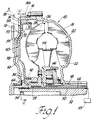
- a hydrodynamic torque transmitting unit 10 is illustrated of the recirculating flow type, hereinafter referred to as a torque converter.
- the torque converter 10 includes an input lug 12 connected to a rotatable annular front cover 14.
- the front cover 14 is connected by suitable fastener means such as lugs 16 to a rear cover 18.
- a pump 20 having a plurality of blades 22 forming a torus operatively connected to the rear cover 18.
- a turbine 24 with a plurality of blades 26 is drivingly connected to a hub 28 splined to a torque transmitting sleeve shaft 30.
- the sleeve shaft 30 is of the type adapted to be connected to a transmission and, in particular, can be connected to a sun gear of a planetary gear unit by suitable clutch means, as is well known in the art.
- the sleeve shaft surrounds a rotatable torque transmitting shaft 32 that extends concentrically within the sleeve shaft 30 in a rearward direction where it can be drivingly connected to a ring gear of a transmission, as is known in the prior art.
- the forward end of the torque transmitting shaft 32 is spline connected to a front annular hub 34.
- the front annular hub 34 has an annular shoulder 36 which connects to a piston plate 38 of a torque converter lock-up clutch 40 constructed in accordance with the present invention. More specifically, the piston plate 38 has an axially directed flange 42 thereon that is secured to the annual hub 34 for rotation therewith.
- the torque converter lock-up clutch 40 is adapted to be energized by hydraulic pressure produced in the torque converter 10 as the pump 20 and turbine 24 are rotated with respect to a bladed stator 44 which is connected through a one way brake 46 to a ground sleeve 48 located radially outwardly of and coaxially along the torque transmitting shaft 32.
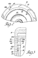
- the lock-up clutch 40 includes a friction lining 50 having a surface 50a thereon bonded to a flat surface portion 54a of the outboard face 54 of the piston plate 38.
- the friction lining 50 further includes an annular seal segment 55 formed continuously circumferentially around the inside diameter surface 56 of the friction lining 50.
- the friction lining 50 further includes a radially outwardly located O.D. surface 58 thereon which is located radially inwardly of an axially directed flange portion 14a of the front cover 14.
- the friction lining 50 further includes a plurality of coolant passages 60 each including a radially angled segment 60a that is located at an inclination with respect to radial lines through the friction lining 50.
- the radially angled segments 60a only extend across part of the width of the friction lining 50 and start at a point located radially outwardly of the I.D. surface 56 and the annular seal segment 55 so that the seal segment 55 will seal a void space 62 located between the outboard surface 38a of the piston plate 38 and the inboard surface 14b of the front cover 14.
- the void space 62 may be relieved of pressure or pressurized through a passage 64 in the hub 34 and a transmission passage 66.
- the annular seal segment 55 will prevent leakage of the actuating fluid back into the void space 62 during energization of the lock-up clutch 40.
- the piston plate 38 is actuated when fluid is exhausted from the space 62 through a converter clutch control valve 65.
- the piston plate 38 is released (disengaged) when the space 62 is pressurized by feeding transmission fluid to the converter from the converter clutch control valve 65 through the passage 66, the passage 64 and into the void space 62.
- the piston plate 38 can be operated to apply a continuously slipping torque between the front face 50b of the friction lining 50 and the inboard surface 14b of the front cover 14.
- the radially angled segments 60a of the coolant passages 60 will receive pressure fluid from a pressure space 70 through inlet openings 72 in the piston plate 38 that are directed axially therethrough at a point radially outwardly of the annular seal segment 55.
- the inlet openings 72 align with axial inlet openings 60b of the coolant passages 60.
- the piston plate 38 will be rotated by the rotatable housing of the torque converter 10 to cause fluid flow through the radially angled segment 60a by a combination of centrifugal force action thereon and a shear force produced by the angle of the groove 60a on fluid forced therein from the pressure space 70. Additionally, there is a pressure differential between the space 70 and the outlet of the passage 60 at the O.D. of the lining 50.
- the groove arrangement thus continuously flows fluid through the friction lining 50. The fluid flow removes heat build-up from the friction lining 50 thereby enabling it to be continuously slipped on the cover 14 and run at higher energy levels as compared to conventional continuous slip lock-up clutch devices.
- the afore described configuration of the friction lining enables the fluid that produces the application pressure on the piston plate 38 also to be used as cooling flow without leakage back into the void space 62 between the outboard surface of the piston plate 38 and the rotating front cover 14.
- the piston plate 38 and the friction lining 50 of the present invention are shown in association with a torque converter having high capacity large diameter pump and turbine components, but are equally suitable for use in any hydrodynamic torque converter having a rotatable housing and including an actuatable piston plate for locking up a clutch component of a torque converter.
- the piston plate 38 has an engagement force to the left as illustrated, which is primarily dependent on pressure within a single pressure space 70, thereby to avoid the need for controls to balance and modulate pressures on either side of the piston plate 38.
- Such a single biasing pressure provides for excellent control of the clutch in a continuous slip mode of operation regardless of pump turbine or clutch plate speed.
- the hydrodynamic torque transmitting unit described above has the advantage that the response time to apply a lock-up force between the piston plate 38 and the rotating front cover 14, either to produce a split torque drive or to produce an all mechanical drive, is minimised. It also has the advantage that heat is continuously removed from the friction lining 50 of the piston plate 38 while providing for a seal across the friction facing means during the slip operation.
Landscapes
- Engineering & Computer Science (AREA)
- General Engineering & Computer Science (AREA)
- Mechanical Engineering (AREA)
- Hydraulic Clutches, Magnetic Clutches, Fluid Clutches, And Fluid Joints (AREA)
- Mechanical Operated Clutches (AREA)
- General Details Of Gearings (AREA)
Claims (8)
- Ensemble de transmission de couple hydrodynamique (10) comprenant des rotors d'entrée et de sortie dans un carter rotatif avec un couvercle avant (14) pouvant être mis en prise avec un plateau d'embrayage (38) actionnable par pression hydraulique pour verrouiller l'ensemble de transmission de couple (10), un espace sous pression (70) sur un premier côté du plateau d'embrayage (38) et un espace vide (62) sur l'autre côté du plateau d'embrayage (38) entre le plateau d'embrayage (38) et le couvercle avant (14) ayant un différentiel de pression à travers ceux-ci qui amènera le plateau d'embrayage (38) à glisser en continu par rapport au couvercle avant (14), et un moyen de garniture de friction annulaire (50) sur l'autre côté du plateau d'embrayage (38), le moyen de garniture de friction (50) comprenant des moyens de joint (55) pouvant être mis en prise avec le couvercle avant (14) pour mettre l'espace vide (62) à l'abri des entrées de fluide en circulation, caractérisé en ce que des moyens de passage (60) sont prévus dans le moyen de garniture de friction annulaire (50) pour faire circuler du fluide provenant de l'espace sous pression (70) à travers le moyen de garniture de friction annulaire (50) entre les moyens de joint (55) et le diamètre extérieur du moyen de garniture de friction annulaire (50) pour évacuer la chaleur du moyen de garniture de friction annulaire (50) lorsque le moyen de garniture de friction annulaire (50) glisse en continu par rapport au couvercle avant (14).
- Ensemble de transmission de couple hydrodynamique selon la revendication 1, dans lequel le moyen de passage (60) comprend des moyens (60a) permettant de faire circuler un débit de refroidissement par la force centrifuge produite par la rotation du plateau d'embrayage (38).
- Ensemble de transmission de couple hydrodynamique selon la revendication 1 ou la revendication 2, dans lequel le moyen de passage (60) comprend des segments inclinés radialement (60a) destinés à appliquer une force de cisaillement sur le fluide sous pression pendant la rotation du plateau d'embrayage (38).
- Ensemble de transmission de couple hydrodynamique selon l'une quelconque des revendications précédentes, comprenant en outre des moyens (72) destinés à diriger du fluide depuis l'espace sous pression (70) jusqu'au moyen de passage (60) pour qu'il s'écoute à travers le moyen de garniture de friction annulaire (50) afin d'en évacuer la chaleur.
- Plateau d'embrayage (38) destiné à être utilisé dans un ensemble de transmission de couple hydrodynamique (10) comportant un carter rotatif avec un couvercle (14), le plateau d'embrayage (38) comportant une garniture de friction annulaire (50) avec des moyens de joint (55) qui y sont fixés pour produire une force de verrouillage sur le couvercle (14) sous l'influence de fluide sous pression provenant d'un espace sous pression (70) situé sur un côté du plateau d'embrayage (38) éloigné du couvercle (14), caractérisé en ce que le plateau d'embrayage (38) comporte un orifice d'admission (72) qui le traverse destiné à fournir un tel fluide sous pression à un passage de refroidissement (60) dans la garniture de friction annulaire (50) pour permettre l'écoulement d'un tel fluide sous pression à travers la garniture de friction annulaire (50) dans une direction radialement vers l'extérieur de sorte que le fluide sous pression agira également comme fluide de refroidissement pour en évacuer la chaleur, et en ce que le moyen de joint (55) de la garniture de friction annulaire (50) comprend un segment de joint annulaire ininterrompu radialement vers l'intérieur du passage de refroidissement (60) et conçu pour venir en contact avec le couvercle (14) pour empêcher le passage de l'écoulement radial intérieur d'un tel fluide au-delà du diamètre intérieur de la garniture de friction annulaire (50).
- Plateau d'embrayage selon la revendication 5, dans lequel le passage de refroidissement (60) comprend une pluralité de rainures (60a) dans la garniture de friction annulaire (50) comportant chacune un orifice d'admission (60b) situé radialement vers l'extérieur du segment de joint annulaire (55) et une ouverture de sortie située dans le diamètre extérieur de la garniture de friction annulaire (50).
- Plateau d'embrayage selon la revendication 5, dans lequel le passage de refroidissement (60) comprend une rainure (60a) inclinée radialement à travers la garniture de friction annulaire (50) comportant un orifice d'admission (60b) situé radialement vers l'extérieur du segment de joint annulaire (55) et un orifice de sortie situé au niveau de la surface radialement le plus à l'extérieur (58) de la garniture de friction annulaire (50).
- Plateau d'embrayage selon la revendication 6 ou la revendication 7, comprenant en outre un trou axial (72) à travers le plateau d'embrayage (38) destiné à former l'orifice d'admission (72) menant à l'orifice d'admission (60b) du passage de refroidissement (60).
Applications Claiming Priority (2)
| Application Number | Priority Date | Filing Date | Title |
|---|---|---|---|
| US436530 | 1989-11-14 | ||
| US07/436,530 US4986397A (en) | 1989-11-14 | 1989-11-14 | Lock-up piston plate for recirculating flow torque converter |
Publications (3)
| Publication Number | Publication Date |
|---|---|
| EP0428248A2 EP0428248A2 (fr) | 1991-05-22 |
| EP0428248A3 EP0428248A3 (en) | 1991-12-04 |
| EP0428248B1 true EP0428248B1 (fr) | 1995-10-18 |
Family
ID=23732780
Family Applications (1)
| Application Number | Title | Priority Date | Filing Date |
|---|---|---|---|
| EP90309068A Expired - Lifetime EP0428248B1 (fr) | 1989-11-14 | 1990-08-17 | Accouplement de pontage pour convertisseur de couple hydrodynamique |
Country Status (6)
| Country | Link |
|---|---|
| US (1) | US4986397A (fr) |
| EP (1) | EP0428248B1 (fr) |
| JP (1) | JP3024997B2 (fr) |
| KR (1) | KR0164849B1 (fr) |
| CA (1) | CA2023059A1 (fr) |
| DE (1) | DE69023098T2 (fr) |
Cited By (2)
| Publication number | Priority date | Publication date | Assignee | Title |
|---|---|---|---|---|
| US6497312B1 (en) | 1999-08-11 | 2002-12-24 | Mannesmann Sachs Ag | Hydrodynamic coupling device |
| US6776272B2 (en) | 2000-02-23 | 2004-08-17 | Zf Friedrichshafen Ag | Friction clutch, especially a torque converter lockup clutch for a hydrodynamic torque converter |
Families Citing this family (46)
| Publication number | Priority date | Publication date | Assignee | Title |
|---|---|---|---|---|
| EP0586304A1 (fr) * | 1992-09-04 | 1994-03-09 | Société Anonyme dite: REGIE NATIONALE DES USINES RENAULT | Convertisseur de couple hydrocinétique pontable et procédé de montage de ce convertisseur. |
| FR2695448B1 (fr) * | 1992-09-04 | 1994-10-21 | Renault | Convertisseur de couple hydrocinétique muni de moyens de pontage perfectionnés. |
| US5320204A (en) * | 1993-01-26 | 1994-06-14 | Borg-Warner Automotive, Inc. | One-way clutch |
| JP3214208B2 (ja) * | 1993-04-13 | 2001-10-02 | トヨタ自動車株式会社 | 湿式クラッチ |
| GB2314142B (en) * | 1993-07-09 | 1998-02-18 | Luk Getriebe Systeme Gmbh | Hydrodynamic torque converter |
| DE4448015B4 (de) * | 1993-07-09 | 2018-10-31 | Schaeffler Technologies Gmbh & Co. Kg | Hydrodynamischer Drehmomentwandler |
| DE4425912A1 (de) * | 1993-07-30 | 1995-02-02 | Luk Getriebe Systeme Gmbh | Hydrodynamischer Strömungswandler |
| DE4338072A1 (de) * | 1993-11-08 | 1994-10-06 | Daimler Benz Ag | Hydrodynamischer Drehmomentwandler mit einer Überbrückungskupplung |
| ES2122821B1 (es) * | 1993-12-22 | 1999-07-01 | Fichtel & Sachs Ag | Convertidor de par de giro hidrodinamico con embrague de puente. |
| DE4416153C2 (de) * | 1994-05-09 | 1996-10-02 | Fichtel & Sachs Ag | Überbrückungskupplung für einen hydrodynamischen Drehmomentwandler |
| DE4432624C1 (de) * | 1994-09-14 | 1996-04-04 | Fichtel & Sachs Ag | Hydrodynamischer Drehmomentwandler mit einer Überbrückungskupplung |
| US6065579A (en) * | 1994-09-30 | 2000-05-23 | Select Powertrain Technologies Corp. | Synchronizer blocker rings used in manual transmissions |
| US5615758A (en) | 1994-09-30 | 1997-04-01 | Nels; Terry E. | Fabric arrangement and method for controlling fluid flow |
| DE19508855C2 (de) * | 1994-10-11 | 1999-03-18 | Mannesmann Sachs Ag | Hydrodynamischer Drehmomentwandler mit einer Überbrückungskupplung |
| FR2725488B1 (fr) * | 1994-10-11 | 1997-01-10 | Fichtel & Sachs Ag | Convertisseur hydrodynamique de couple de rotation comportant un accouplement de pontage |
| FR2726621B1 (fr) * | 1994-11-04 | 1997-01-03 | Renault | Convertisseur hydrocinetique de couple pontable |
| JP3020017B2 (ja) * | 1994-11-07 | 2000-03-15 | 大同メタル工業株式会社 | 湿式摩擦部材 |
| JP3623547B2 (ja) * | 1995-04-14 | 2005-02-23 | Nskワーナー株式会社 | ロックアップ機構付きトルクコンバータ |
| US5566802A (en) * | 1995-07-17 | 1996-10-22 | Borg-Warner Automotive, Inc. | Continuous slip hydrokinetic torque converter clutch interface with curcuitous groove for cooling and wetting clutch interface zone |
| US6035991A (en) * | 1996-12-11 | 2000-03-14 | Advanced Friction Materials, Inc. | Blocked slot clutch plate lining |
| DE10066386B4 (de) * | 1999-08-11 | 2012-04-26 | Zf Friedrichshafen Ag | Hydrodynamische Kopplungseinrichtung |
| JP2002181073A (ja) * | 2000-12-18 | 2002-06-26 | Aisin Aw Co Ltd | 摩擦材の油溝形状 |
| DE10131093A1 (de) | 2001-06-27 | 2003-01-09 | Zf Sachs Ag | Überbrückungskupplung für einen hydrodynamischen Drehmomentwandler |
| DE10230650A1 (de) * | 2001-07-11 | 2003-04-03 | Luk Lamellen & Kupplungsbau | Hydraulischer Drehmomentwandler |
| JP4217709B2 (ja) | 2003-02-18 | 2009-02-04 | 財団法人国際科学振興財団 | 携帯端末用アンテナおよびそれを用いた携帯端末 |
| US7014024B2 (en) * | 2003-06-11 | 2006-03-21 | Sulzer Euroflamm Us Inc. | System and method for improving cooling in a friction facing environment |
| US7014027B2 (en) * | 2003-07-14 | 2006-03-21 | Borgwarner Inc. | Friction material having oil localization slots |
| US7168544B2 (en) * | 2003-10-02 | 2007-01-30 | Sulzer Euroflamm Us Inc. | Friction facing material for use in a friction environment |
| US20060236523A1 (en) * | 2003-10-02 | 2006-10-26 | Sulzer Euroflamm Us Inc | Friction facing method for use in a friction environment |
| US20050075021A1 (en) * | 2003-10-03 | 2005-04-07 | Lam Robert C. | High performance, durable, deposit friction material |
| US20050074595A1 (en) * | 2003-10-03 | 2005-04-07 | Lam Robert C. | Friction material containing partially carbonized carbon fibers |
| US8021744B2 (en) * | 2004-06-18 | 2011-09-20 | Borgwarner Inc. | Fully fibrous structure friction material |
| US7429418B2 (en) | 2004-07-26 | 2008-09-30 | Borgwarner, Inc. | Porous friction material comprising nanoparticles of friction modifying material |
| US8603614B2 (en) | 2004-07-26 | 2013-12-10 | Borgwarner Inc. | Porous friction material with nanoparticles of friction modifying material |
| US7357233B2 (en) * | 2005-02-15 | 2008-04-15 | Borgwarner Inc. | Torque converter with a lock-up clutch assembly having a floating friction disk |
| WO2006116474A2 (fr) * | 2005-04-26 | 2006-11-02 | Borgwarner Inc. | Materiau de friction |
| US8394452B2 (en) * | 2005-11-02 | 2013-03-12 | Borgwarner Inc. | Carbon friction materials |
| JP2007146927A (ja) * | 2005-11-25 | 2007-06-14 | Nsk Warner Kk | ロックアップクラッチ |
| JP4781792B2 (ja) * | 2005-11-25 | 2011-09-28 | Nskワーナー株式会社 | ロックアップクラッチ |
| US20070270069A1 (en) * | 2006-05-18 | 2007-11-22 | Sulzer Euroflamm Us Inc. | Friction material and system and method for making the friction material |
| EP2028221A1 (fr) * | 2007-08-03 | 2009-02-25 | Borgwarner, Inc. | Matériau de friction avec du silicone |
| DE102008013907B4 (de) | 2008-03-12 | 2016-03-10 | Borgwarner Inc. | Reibschlüssig arbeitende Vorrichtung mit mindestens einer Reiblamelle |
| DE102009030506A1 (de) * | 2008-06-30 | 2009-12-31 | Borgwarner Inc., Auburn Hills | Reibungsmaterialien |
| US10844941B2 (en) | 2016-05-16 | 2020-11-24 | Allison Transmission, Inc. | Torque converter one-way flow device and method to enable lockup clutch application |
| US10663049B2 (en) * | 2017-10-03 | 2020-05-26 | Schaeffler Technologies AG & Co. KG | Torque converter impeller or turbine including rear side embossment |
| US10711873B2 (en) * | 2018-06-19 | 2020-07-14 | Schaeffler Technologies AG & Co. KG | Hydrodynamic side plate for torque converter stator |
Citations (2)
| Publication number | Priority date | Publication date | Assignee | Title |
|---|---|---|---|---|
| US4469206A (en) * | 1981-02-21 | 1984-09-04 | Aisin Warner Kabushiki Kaisha | Hydraulically-operated frictional engagement device |
| US4638897A (en) * | 1982-06-24 | 1987-01-27 | Honda Giken Kogyo Kabushiki Kaisha | Damper device for a torque converter clutch |
Family Cites Families (8)
| Publication number | Priority date | Publication date | Assignee | Title |
|---|---|---|---|---|
| US2841262A (en) * | 1952-05-16 | 1958-07-01 | Borg Warner | Clutch |
| FR1377344A (fr) * | 1963-08-06 | 1964-11-06 | Francois Du Ferodo Sa | Perfectionnements aux transmissions |
| US3695407A (en) * | 1970-04-23 | 1972-10-03 | Walter E Peery | Frictional torque transferring apparatus with a liquid mercury cooling system |
| US4199047A (en) * | 1977-11-09 | 1980-04-22 | Ford Motor Company | Hydrokinetic torque converter with lock-up clutch |
| US4181203A (en) * | 1978-08-14 | 1980-01-01 | General Motors Corporation | Control for a torque converter slipping clutch |
| US4177885A (en) * | 1978-10-13 | 1979-12-11 | General Motors Corporation | Torque converter and lock-up clutch |
| JPS5830532A (ja) * | 1981-08-17 | 1983-02-23 | Mitsubishi Motors Corp | 摩擦クラツチのフエ−シング構造 |
| US4445599A (en) * | 1981-10-27 | 1984-05-01 | Eaton Corporation | Cooling means for torque converter bypass |
-
1989
- 1989-11-14 US US07/436,530 patent/US4986397A/en not_active Expired - Lifetime
-
1990
- 1990-08-10 CA CA002023059A patent/CA2023059A1/fr not_active Abandoned
- 1990-08-17 EP EP90309068A patent/EP0428248B1/fr not_active Expired - Lifetime
- 1990-08-17 DE DE69023098T patent/DE69023098T2/de not_active Expired - Lifetime
- 1990-11-09 JP JP2305930A patent/JP3024997B2/ja not_active Expired - Fee Related
- 1990-11-12 KR KR1019900018210A patent/KR0164849B1/ko not_active Expired - Fee Related
Patent Citations (2)
| Publication number | Priority date | Publication date | Assignee | Title |
|---|---|---|---|---|
| US4469206A (en) * | 1981-02-21 | 1984-09-04 | Aisin Warner Kabushiki Kaisha | Hydraulically-operated frictional engagement device |
| US4638897A (en) * | 1982-06-24 | 1987-01-27 | Honda Giken Kogyo Kabushiki Kaisha | Damper device for a torque converter clutch |
Cited By (2)
| Publication number | Priority date | Publication date | Assignee | Title |
|---|---|---|---|---|
| US6497312B1 (en) | 1999-08-11 | 2002-12-24 | Mannesmann Sachs Ag | Hydrodynamic coupling device |
| US6776272B2 (en) | 2000-02-23 | 2004-08-17 | Zf Friedrichshafen Ag | Friction clutch, especially a torque converter lockup clutch for a hydrodynamic torque converter |
Also Published As
| Publication number | Publication date |
|---|---|
| CA2023059A1 (fr) | 1991-05-15 |
| EP0428248A3 (en) | 1991-12-04 |
| JP3024997B2 (ja) | 2000-03-27 |
| EP0428248A2 (fr) | 1991-05-22 |
| DE69023098T2 (de) | 1996-03-21 |
| KR910010088A (ko) | 1991-06-28 |
| KR0164849B1 (ko) | 1998-12-15 |
| US4986397A (en) | 1991-01-22 |
| DE69023098D1 (de) | 1995-11-23 |
| JPH03209045A (ja) | 1991-09-12 |
Similar Documents
| Publication | Publication Date | Title |
|---|---|---|
| EP0428248B1 (fr) | Accouplement de pontage pour convertisseur de couple hydrodynamique | |
| US4199047A (en) | Hydrokinetic torque converter with lock-up clutch | |
| US4194604A (en) | Hydrodynamic torque convertor with double circuit torus flow and lock-up clutch | |
| US6290046B2 (en) | Friction liner having a network of grooves, for a clutch | |
| EP0407895B1 (fr) | Accouplement de pontage glissant pour convertisseur de couple hydrodynamique | |
| US5441135A (en) | Hydrodynamic torque converter with lock-up clutch | |
| US4454786A (en) | Four speed torque converter transaxle and accessory drive system | |
| US3463033A (en) | Multiple ratio hydrokinetic torque converter transmission with split-torque lock-up clutches in the converter housing | |
| JPH07180768A (ja) | ロックアップ機構付きトルクコンバータ | |
| KR20040084859A (ko) | 클러치 하우징 내부에 클러치 기구를 구비하는 유압클러치 장치 | |
| US3213983A (en) | Fluid actuated transmission device | |
| US3734251A (en) | Hydrodynamic unit with mechanical drive clutch | |
| US3491865A (en) | Clutch structure with segmented clutch plates | |
| EP0409088B1 (fr) | Assemblage de convertisseur de couple avec embrayage de dérivation actif en inverse | |
| JP2006226526A (ja) | フローティング摩擦ディスクを持つロックアップクラッチ組立体を含むトルクコンバーター | |
| US6343679B1 (en) | Hydrodynamic clutch device, in particular hydrodynamic torque converter | |
| EP0191987B1 (fr) | Unité d'embrayage à démarrage actionnée hydrauliquement | |
| US4033436A (en) | Transmission and torque converter with lock-up clutch | |
| US5819896A (en) | Variable flow rate torque converter lockup clutch | |
| US3547235A (en) | Hydrodynamic and friction coupling | |
| US3777863A (en) | Hydrodynamic unit with friction clutch | |
| US4011776A (en) | Transmission | |
| JP2007534898A (ja) | ハイドロダイナミッククラッチ | |
| EP3571426B1 (fr) | Piston de turbine pour convertisseur de couple hydrocinétique et procédé de fonctionnement | |
| CN113153942A (zh) | 湿式摩擦联接装置 |
Legal Events
| Date | Code | Title | Description |
|---|---|---|---|
| PUAI | Public reference made under article 153(3) epc to a published international application that has entered the european phase |
Free format text: ORIGINAL CODE: 0009012 |
|
| AK | Designated contracting states |
Kind code of ref document: A2 Designated state(s): DE ES FR GB IT |
|
| PUAL | Search report despatched |
Free format text: ORIGINAL CODE: 0009013 |
|
| AK | Designated contracting states |
Kind code of ref document: A3 Designated state(s): DE ES FR GB IT |
|
| 17P | Request for examination filed |
Effective date: 19920413 |
|
| 17Q | First examination report despatched |
Effective date: 19931213 |
|
| GRAA | (expected) grant |
Free format text: ORIGINAL CODE: 0009210 |
|
| AK | Designated contracting states |
Kind code of ref document: B1 Designated state(s): DE ES FR GB IT |
|
| PG25 | Lapsed in a contracting state [announced via postgrant information from national office to epo] |
Ref country code: IT Free format text: LAPSE BECAUSE OF FAILURE TO SUBMIT A TRANSLATION OF THE DESCRIPTION OR TO PAY THE FEE WITHIN THE PRESCRIBED TIME-LIMIT;WARNING: LAPSES OF ITALIAN PATENTS WITH EFFECTIVE DATE BEFORE 2007 MAY HAVE OCCURRED AT ANY TIME BEFORE 2007. THE CORRECT EFFECTIVE DATE MAY BE DIFFERENT FROM THE ONE RECORDED. Effective date: 19951018 Ref country code: ES Free format text: THE PATENT HAS BEEN ANNULLED BY A DECISION OF A NATIONAL AUTHORITY Effective date: 19951018 |
|
| REF | Corresponds to: |
Ref document number: 69023098 Country of ref document: DE Date of ref document: 19951123 |
|
| ET | Fr: translation filed | ||
| PLBE | No opposition filed within time limit |
Free format text: ORIGINAL CODE: 0009261 |
|
| STAA | Information on the status of an ep patent application or granted ep patent |
Free format text: STATUS: NO OPPOSITION FILED WITHIN TIME LIMIT |
|
| 26N | No opposition filed | ||
| REG | Reference to a national code |
Ref country code: GB Ref legal event code: IF02 |
|
| PGFP | Annual fee paid to national office [announced via postgrant information from national office to epo] |
Ref country code: FR Payment date: 20090806 Year of fee payment: 20 |
|
| PGFP | Annual fee paid to national office [announced via postgrant information from national office to epo] |
Ref country code: DE Payment date: 20090831 Year of fee payment: 20 Ref country code: GB Payment date: 20090708 Year of fee payment: 20 |
|
| REG | Reference to a national code |
Ref country code: GB Ref legal event code: PE20 Expiry date: 20100816 |
|
| PG25 | Lapsed in a contracting state [announced via postgrant information from national office to epo] |
Ref country code: GB Free format text: LAPSE BECAUSE OF EXPIRATION OF PROTECTION Effective date: 20100816 |
|
| PG25 | Lapsed in a contracting state [announced via postgrant information from national office to epo] |
Ref country code: DE Free format text: LAPSE BECAUSE OF EXPIRATION OF PROTECTION Effective date: 20100817 |