EP0409127A2 - Frequenzsynthetisierer mit einem einen verbesserten Regelkreisgang enthaltenden Phasenregelkreis - Google Patents
Frequenzsynthetisierer mit einem einen verbesserten Regelkreisgang enthaltenden Phasenregelkreis Download PDFInfo
- Publication number
- EP0409127A2 EP0409127A2 EP90113550A EP90113550A EP0409127A2 EP 0409127 A2 EP0409127 A2 EP 0409127A2 EP 90113550 A EP90113550 A EP 90113550A EP 90113550 A EP90113550 A EP 90113550A EP 0409127 A2 EP0409127 A2 EP 0409127A2
- Authority
- EP
- European Patent Office
- Prior art keywords
- signal
- frequency
- coupled
- receive
- generating
- Prior art date
- Legal status (The legal status is an assumption and is not a legal conclusion. Google has not performed a legal analysis and makes no representation as to the accuracy of the status listed.)
- Withdrawn
Links
Images


Classifications
-
- H—ELECTRICITY
- H03—ELECTRONIC CIRCUITRY
- H03L—AUTOMATIC CONTROL, STARTING, SYNCHRONISATION OR STABILISATION OF GENERATORS OF ELECTRONIC OSCILLATIONS OR PULSES
- H03L7/00—Automatic control of frequency or phase; Synchronisation
- H03L7/06—Automatic control of frequency or phase; Synchronisation using a reference signal applied to a frequency- or phase-locked loop
- H03L7/16—Indirect frequency synthesis, i.e. generating a desired one of a number of predetermined frequencies using a frequency- or phase-locked loop
- H03L7/18—Indirect frequency synthesis, i.e. generating a desired one of a number of predetermined frequencies using a frequency- or phase-locked loop using a frequency divider or counter in the loop
- H03L7/183—Indirect frequency synthesis, i.e. generating a desired one of a number of predetermined frequencies using a frequency- or phase-locked loop using a frequency divider or counter in the loop a time difference being used for locking the loop, the counter counting between fixed numbers or the frequency divider dividing by a fixed number
- H03L7/185—Indirect frequency synthesis, i.e. generating a desired one of a number of predetermined frequencies using a frequency- or phase-locked loop using a frequency divider or counter in the loop a time difference being used for locking the loop, the counter counting between fixed numbers or the frequency divider dividing by a fixed number using a mixer in the loop
Definitions
- the present invention relates to a frequency synthesizer using a phase-locked loop. More specifically, the present invention relates to such a phase-locked loop type frequency synthesizer which features a quick loop response even when frequency separation of the output signals is narrowed.
- a frequency synthesizer is a combination of circuit functions which generates, or synthesize, many output signals from only a few input signals. Preferably, only one input signal is required and typically, a single output signal out of several hundreds or thousand possibilities is generated at a time.
- a phase-locked loop offers an ideal solution to frequency synthesis.
- the PLL is essentially a closed loop electronic servomechanism whose output is locked onto, and will track, a reference signal. This is accomplished using three basic elements: a phase detector, a loop filter (low-pass filter), and a voltage controlled oscillator (VOC).
- a reference signal also is required as a second input to the phase detector.
- a known frequency synthesizer 10 comprises a reference oscillator 12 which generates a signal of suitable frequency accuracy and stability to satisfy system requirements.
- An output Fp of the reference oscillator 12 is applied to a fixed frequency divider 14.
- the divider 14 divides the reference oscillator frequency Fp using a given divide value and generates a reference signal Fr.
- the reference signal Fr is fed to a phase detector 16 which also receives a signal Fv from a variable frequency divider 18.
- the phase detector 16 compares the phases of the two signals Fr and Fv, and generates an error signal which is proportional to the phase difference between said two signals Fr and Fv.
- the error signal is filtered by a loop filter (low-pass filter) 20 to smooth and shape it into a voltage suitable for controlling a VCO 22.
- a loop filter low-pass filter
- the output frequency Fvco of the VCO 22 is induced to change in a direction to establish a constant phase difference (typically "zero") between the two signals Fr and Fv.
- the output signal Fvco of the VCO 22 is also the output Fout of the synthesizer 10 and is applied to external circuitry through an output terminal 24.
- the signal Fvco is split and fed back to the variable frequency divider 18. It is typical to use a programmable counter as the variable frequency divider 18.
- an open loop gain of a PLL type frequency synthesizer is lowered in that the open loop gain is inversely proportional to the divide value Nv.
- the known frequency synthesizer has encountered the difficulties in that a switching time for changing output frequencies is decreased.
- a cut off frequency of the low pass filter 20 should be reduced for sufficiently attenuating undesired frequency components of Fr, which leaks from the phase detector 16. This also causes a loop response slow down.
- Another object of the present invention is to provide a frequency synthesizer using a phase-locked loop which features a high switching time for changing output frequencies.
- the frequency synthesis is accomplished by a closed loop arrangement comprising: a reference oscillator, a phase detector, a programmable counter, a phase detector, a loop filter, a voltage controlled oscillator (VCO), and a frequency translator.
- the phase detector is supplied with a reference signal from the reference oscillator and a signal from the programmable counter, and compares phases of the two signals.
- a frequency translator is provided in a manner to receive the signal from the VCO and downward translate the frequency of the signal received.
- the output of the frequency translator is fed to the programmable counter which divides a signal applied by a variable divide value and applies the divided signal to the phase detector.
- a first aspect of the present invention comes in a frequency synthesizer using a phase-locked loop, comprising: first means, the first means generating a reference signal; second means, the second means receiving a second signal and dividing the frequency of the second signal by a variable divide value and outputting a third signal; third means, the third means coupled to receive the reference signal and the third signal, the third means comparing phases of the reference signal and the third signal and generating an error signal; fourth means, the fourth means coupled to receive the error signal and generating a fourth signal which is controlled in frequency by the error signal and which is derived as an output of the frequency synthesizer; and fifth means, the fifth means being coupled to receive the fourth signal, the fifth means translating the frequency of the fourth signal downward and applying the downward translated frequency signal to the second means as the second signal.
- a second aspect of the present invention comes in a frequency synthesizer using a phase-locked loop, comprising: first means, the first means generating a reference signal; second means, the second means receiving a second signal and dividing the frequency of the second signal by a variable divide value and outputting a third signal; third means, the third means coupled to receive the reference signal and the third signal, the third means comparing phases of the reference signal and the third signal and generating an error signal; fourth means, the fourth means receiving the error signal and generating a fourth signal whose frequency is controlled by the error signal; and fifth means, the fifth means coupled to receive the fourth signal, the fifth means dividing the frequency of the fourth signal by a predetermined divide value and generating a fifth signal as an output of the frequency synthesizer.
- a third aspect of the present invention takes a form of a frequency synthesizer using a phase-locked loop, comprising: first means, the first means generating a reference signal; second means, the second means receiving a second signal and dividing the frequency of the second signal by a variable divide value and outputting a third signal; third means, the third means coupled to receive the reference signal and the third signal, the third means comparing phases of the reference signal and the third signal and generating an error signal; fourth means, the fourth means receiving the error signal and generating a fourth signal whose frequency is controlled by the error signal; fifth means, the fifth means coupled to receive the fourth signal, the fifth means dividing the frequency of the fourth signal by a predetermined divide value and generating a fifth signal; seventh means, the seventh means being coupled to receive the fifth signal, the seventh means translating the frequency of the fifth signal upward and applying the upward translated frequency signal as an output signal of the frequency synthesizer.
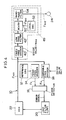
- the first embodiment features a provision of a frequency translator 30 in the feedback loop of the frequency synthesizer 10.
- the remaining portions of the Fig. 2 arrangement are exactly the same as those of the Fig. 1 arrangement, and hence the descriptions thereof will be omitted for the sake of brevity.
- Nv Fm/Fr (2) Accordingly, if the frequency Fm is set to a relatively low frequency, then the channel spacing can be narrowed (Fr can be reduced) while maintaining the divide value Nv at a low level. In other words, even if the channel spacing is narrowed, there is no need to increase Nv. Thus, a loop gain is not lowered and can even be raised. Accordingly, high speed switching of the output frequencies Fout is rendered possible.
- the output frequency Fout of the synthesizer 10 is represented by the following equation (3) when the synthesizer is in a "locked condition".
- FIG. 3 wherein a second embodiment of this invention is illustrated in block diagram form.
- the arrangement of Fig. 3 includes a fixed frequency divider 40 and a low pass filter 42.
- the remaining portions of the Fig. 3 arrangement are exactly the same as those of the Fig. 1 arrangement, and hence the descriptions thereof will be omitted for simplicity.
- the synthesizer output Fout is 40 MHz ⁇ 5 KHz
- a channel spacing is 50 Hz
- the divide value Nout is 20, then the output frequency of the VCO 22 becomes 800 MHz ⁇ 100 KHz from equation (4).
- Fig. 4 shows a variant of the second embodiment in block diagram form.
- the arrangement of Fig. 4 differs from that of Fig. 3 in that the former arrangement further includes a frequency translator 49 which comprises: a mixer 50, a local oscillator 52 and a band pass filter 54.
- Fout Fvco/Nout (equation (4)). Accordingly, if Nout is set at a relatively high value while maintaining the synthesizer output frequency Fout high, then the output Fvco of the VCO 22 become very high with the result that the VCO 22 is practically very difficult to be manufactured and hence the entire circuitry of Fig. 3 becomes difficult to actually implement. It follows that if a high frequency synthesizer output Fout is necessary, the divide value Nout of the divider 40 can not be set to a large value from a practical point of view. Consequently, a quick loop response is unable to be attained. This modification is directed to solving this difficulty.
- the frequency translator 49 translates the output frequency of the low-pass filter 42 upward.
- This upward frequency translation is accomplished by multiplication of the output signal of the filter 42 by a locally generated signal Floc, and subsequent band-pass filtering.
- the mixer 50 is supplied with the output of the low-pass filter 42 and up mixes the same (viz., translates the incoming frequency upward) using the local frequency Floc generated by the oscillator 52.
- the output of the mixer 50 is applied to the output terminal 24 after being band-pass filtered.
Landscapes
- Stabilization Of Oscillater, Synchronisation, Frequency Synthesizers (AREA)
- Acyclic And Carbocyclic Compounds In Medicinal Compositions (AREA)
Applications Claiming Priority (4)
| Application Number | Priority Date | Filing Date | Title |
|---|---|---|---|
| JP185424/89 | 1989-07-17 | ||
| JP1185424A JPH0349320A (ja) | 1989-07-17 | 1989-07-17 | 周波数シンセサイザ |
| JP1196608A JPH0362620A (ja) | 1989-07-31 | 1989-07-31 | 周波数シンセサイザ |
| JP196608/89 | 1989-07-31 |
Publications (2)
| Publication Number | Publication Date |
|---|---|
| EP0409127A2 true EP0409127A2 (de) | 1991-01-23 |
| EP0409127A3 EP0409127A3 (en) | 1991-04-10 |
Family
ID=26503092
Family Applications (1)
| Application Number | Title | Priority Date | Filing Date |
|---|---|---|---|
| EP19900113550 Withdrawn EP0409127A3 (en) | 1989-07-17 | 1990-07-16 | Phase-locked loop type frequency synthesizer having improved loop response |
Country Status (3)
| Country | Link |
|---|---|
| EP (1) | EP0409127A3 (de) |
| AU (1) | AU5912490A (de) |
| CA (1) | CA2021233A1 (de) |
Cited By (3)
| Publication number | Priority date | Publication date | Assignee | Title |
|---|---|---|---|---|
| EP0721140A1 (de) * | 1995-01-05 | 1996-07-10 | Nec Corporation | Frequenzmodulationssignalquelle mit Hochgeschwindigkeitsschaltung und optischer Wellenlängenfilter |
| WO2005078916A1 (en) | 2004-02-10 | 2005-08-25 | Bitwave Semiconductor | Programmable radio transceiver |
| US7158767B2 (en) | 2003-10-24 | 2007-01-02 | Cts Corporation | Tuneable frequency translator |
Family Cites Families (7)
| Publication number | Priority date | Publication date | Assignee | Title |
|---|---|---|---|---|
| JPS5382111A (en) * | 1976-12-27 | 1978-07-20 | Sanyo Electric Co Ltd | Preventive unit of illegal electromagnetic waves for transmitters |
| JPS54118759A (en) * | 1978-03-08 | 1979-09-14 | Hitachi Denshi Ltd | Synthesized oscillator for radio device |
| JPS5732133A (en) * | 1980-08-04 | 1982-02-20 | Advantest Corp | Phase-synchronous oscillator |
| GB2098419A (en) * | 1981-05-07 | 1982-11-17 | Racal Res Ltd | Electrical frequency adjusting arrangements |
| JPS58101531A (ja) * | 1981-12-14 | 1983-06-16 | Marantz Japan Inc | 周波数シンセサイザ |
| EP0278140A1 (de) * | 1987-02-12 | 1988-08-17 | Hewlett-Packard Limited | Taktsignalgenerator |
| US4882549A (en) * | 1988-11-16 | 1989-11-21 | Zvi Galani | Center offset microwave frequency synthesizer |
-
1990
- 1990-07-16 EP EP19900113550 patent/EP0409127A3/en not_active Withdrawn
- 1990-07-16 CA CA 2021233 patent/CA2021233A1/en not_active Abandoned
- 1990-07-17 AU AU59124/90A patent/AU5912490A/en not_active Abandoned
Cited By (5)
| Publication number | Priority date | Publication date | Assignee | Title |
|---|---|---|---|---|
| EP0721140A1 (de) * | 1995-01-05 | 1996-07-10 | Nec Corporation | Frequenzmodulationssignalquelle mit Hochgeschwindigkeitsschaltung und optischer Wellenlängenfilter |
| US5812302A (en) * | 1995-01-05 | 1998-09-22 | Nec Corporation | High-speed frequency modulation signal source and high-speed variable optical wavelength filter |
| AU714152B2 (en) * | 1995-01-05 | 1999-12-23 | Nec Corporation | High-speed frequency modulation signal source and high-speed variable optical wavelength filter |
| US7158767B2 (en) | 2003-10-24 | 2007-01-02 | Cts Corporation | Tuneable frequency translator |
| WO2005078916A1 (en) | 2004-02-10 | 2005-08-25 | Bitwave Semiconductor | Programmable radio transceiver |
Also Published As
| Publication number | Publication date |
|---|---|
| CA2021233A1 (en) | 1991-01-18 |
| EP0409127A3 (en) | 1991-04-10 |
| AU5912490A (en) | 1991-01-17 |
Similar Documents
| Publication | Publication Date | Title |
|---|---|---|
| EP0659313B1 (de) | Harmonischer frequenzsynthetisierer mit einstellbarem frequenzversatz | |
| US5259007A (en) | Phase locked loop frequency synthesizer | |
| US5451910A (en) | Frequency synthesizer with comb spectrum mixer and fractional comb frequency offset | |
| US5329253A (en) | Frequency synthesis using frequency controlled carrier modulated with PLL feedback signal | |
| US5140284A (en) | Broad band frequency synthesizer for quick frequency retuning | |
| US5391996A (en) | Techniques for generating two high frequency signals with a constant phase difference over a wide frequency band | |
| JP3001735B2 (ja) | 位相同期ループ周波数シンセサイザ | |
| EP0393975A1 (de) | Digitaler Frequenzsynthetisierer | |
| US7180377B1 (en) | Method and apparatus for a hybrid phase lock loop frequency synthesizer | |
| US5831481A (en) | Phase lock loop circuit having a broad loop band and small step frequency | |
| CA2010176A1 (en) | Tuner station selecting apparatus | |
| US20020131541A1 (en) | Spread spectrum modulation technique for frequency synthesizers | |
| US4785260A (en) | Frequency synthesizer for broadcast telephone system having multiple assignable frequency channels | |
| US6137368A (en) | Frequency synthesizer with constant loop characteristics | |
| US3546617A (en) | Digital frequency synthesizer | |
| US3268831A (en) | Automatic frequency controlled multi-channel generator | |
| US4862107A (en) | Frequency synthesizer for broadcast telephone system having multiple assignable frequency channels | |
| US4095190A (en) | Tuning system | |
| US4871981A (en) | Fast hopping microwave frequency synthesizer | |
| JPS61265923A (ja) | 周波数シンセサイザのチヤンネル化を助長するための電子回路装置 | |
| EP1107458B1 (de) | System zum Begrenzen der Zwischenfrequenzänderung in Phasenregelkreisen | |
| EP0566274A1 (de) | Frequenzsynthetisierer mit einem Phasenregelkreis | |
| US4186356A (en) | Phase locked loop frequency synthesizer and frequency modulator | |
| KR960027347A (ko) | 이득 제어 기능을 갖는 광대역 위상동기루프(pll) 주파수 합성기 | |
| KR960007404B1 (ko) | 저속 데이타 변조가 가능한 주파수 편이 변조 회로 |
Legal Events
| Date | Code | Title | Description |
|---|---|---|---|
| PUAI | Public reference made under article 153(3) epc to a published international application that has entered the european phase |
Free format text: ORIGINAL CODE: 0009012 |
|
| 17P | Request for examination filed |
Effective date: 19900814 |
|
| AK | Designated contracting states |
Kind code of ref document: A2 Designated state(s): DE FR GB IT NL SE |
|
| PUAL | Search report despatched |
Free format text: ORIGINAL CODE: 0009013 |
|
| AK | Designated contracting states |
Kind code of ref document: A3 Designated state(s): DE FR GB IT NL SE |
|
| STAA | Information on the status of an ep patent application or granted ep patent |
Free format text: STATUS: THE APPLICATION HAS BEEN WITHDRAWN |
|
| 18W | Application withdrawn |
Withdrawal date: 19910926 |