EP0409260A2 - Récepteur pour communication optique cohérente - Google Patents
Récepteur pour communication optique cohérente Download PDFInfo
- Publication number
- EP0409260A2 EP0409260A2 EP90113950A EP90113950A EP0409260A2 EP 0409260 A2 EP0409260 A2 EP 0409260A2 EP 90113950 A EP90113950 A EP 90113950A EP 90113950 A EP90113950 A EP 90113950A EP 0409260 A2 EP0409260 A2 EP 0409260A2
- Authority
- EP
- European Patent Office
- Prior art keywords
- signal
- optical
- electrical
- local
- input port
- Prior art date
- Legal status (The legal status is an assumption and is not a legal conclusion. Google has not performed a legal analysis and makes no representation as to the accuracy of the status listed.)
- Granted
Links
Images


Classifications
-
- H—ELECTRICITY
- H04—ELECTRIC COMMUNICATION TECHNIQUE
- H04B—TRANSMISSION
- H04B10/00—Transmission systems employing electromagnetic waves other than radio-waves, e.g. infrared, visible or ultraviolet light, or employing corpuscular radiation, e.g. quantum communication
- H04B10/60—Receivers
- H04B10/61—Coherent receivers
-
- H—ELECTRICITY
- H04—ELECTRIC COMMUNICATION TECHNIQUE
- H04B—TRANSMISSION
- H04B10/00—Transmission systems employing electromagnetic waves other than radio-waves, e.g. infrared, visible or ultraviolet light, or employing corpuscular radiation, e.g. quantum communication
- H04B10/25—Arrangements specific to fibre transmission
- H04B10/2507—Arrangements specific to fibre transmission for the reduction or elimination of distortion or dispersion
- H04B10/2513—Arrangements specific to fibre transmission for the reduction or elimination of distortion or dispersion due to chromatic dispersion
-
- H—ELECTRICITY
- H04—ELECTRIC COMMUNICATION TECHNIQUE
- H04B—TRANSMISSION
- H04B10/00—Transmission systems employing electromagnetic waves other than radio-waves, e.g. infrared, visible or ultraviolet light, or employing corpuscular radiation, e.g. quantum communication
- H04B10/60—Receivers
- H04B10/61—Coherent receivers
- H04B10/613—Coherent receivers including phase diversity, e.g., having in-phase and quadrature branches, as in QPSK coherent receivers
-
- H—ELECTRICITY
- H04—ELECTRIC COMMUNICATION TECHNIQUE
- H04B—TRANSMISSION
- H04B10/00—Transmission systems employing electromagnetic waves other than radio-waves, e.g. infrared, visible or ultraviolet light, or employing corpuscular radiation, e.g. quantum communication
- H04B10/60—Receivers
- H04B10/61—Coherent receivers
- H04B10/63—Homodyne, i.e. coherent receivers where the local oscillator is locked in frequency and phase to the carrier signal
-
- H—ELECTRICITY
- H04—ELECTRIC COMMUNICATION TECHNIQUE
- H04B—TRANSMISSION
- H04B10/00—Transmission systems employing electromagnetic waves other than radio-waves, e.g. infrared, visible or ultraviolet light, or employing corpuscular radiation, e.g. quantum communication
- H04B10/60—Receivers
- H04B10/61—Coherent receivers
- H04B10/64—Heterodyne, i.e. coherent receivers where, after the opto-electronic conversion, an electrical signal at an intermediate frequency [IF] is obtained
Definitions
- the present invention relates to a receiver for coherent communication and, more specifically, to improvements in a phase diversity receiver for coherent optical communication.
- the coherent optical communication system is suitable for long-distance signal transmission because its receiving sensitivity is higher than the current, practical intensity modulation direct detection system, and is suitable for bulk transmission owing to its capability of high-density multiplexing in transmitting signals using electromagnetic waves of frequencies in the frequency range of near visible light.
- the heterodyne system, the homodyne system and the phase diversity system are generally known as receiving systems for coherent optical communication.
- the phase diversity system in particular, is suitable for high-speed transmission because the band width for the light wave detector (photoelectric converter) is half that for the photodetector of the heterodyne system.
- the phase diversity system as compared with the homodyne system, is suitable for practical application because the phase diversity system does not require a light source with a very narrow spectral line width for emitting a carrier beam and a local-oscillator beam and does not need any phase locking circuit.
- the heterodyne system is capable of compensating chromatic dispersion (group delay) in the optical fiber in the IF band (the intermediate frequency band)
- the homodyne system or the phase diversity system which obtains signals directly in the baseband, is unable, in general, to compensate dispersion easily because the upper sideband and the lower sideband are folded. Accordingly, the phase diversity system needs improvements to enable the phase diversity system to compensate dispersion easily.
- the heterodyne system mixes a received signal beam and a local-oscillator beam by the square-law function of the photodetector to produce an IF signal having a frequency, for example, a frequency in the microwave frequency range, corresponding to the difference between the frequency of the signal beam and that of the local-oscillator beam and demodulates the IF signal.
- the photodetector provides an IF signal having an amplitude proportional to the product of the amplitude of the received signal beam and that of the local-oscillator beam and, therefore, signals can be received at a a high sensitivity by using a local-oscillator beam of an appropriate intensity.
- a band for the photodetector is in the range of 0.5B to 2.5B when the intermediate frequency f IF is, for example, 1.5 times the bit rate B. Accordingly, when the bit rate is 10 Gb/s, the frequency band must be from 5 GHz to 25 GHz.
- the heterodyne system Since it is difficult to provide a photodetector having a flat frequency response characteristic and a satisfactory noise characteristic in such a frequency band, the heterodyne system is not necessarily suitable for high-speed transmission. However, since the heterodyne system is able to achieve demodulation through envelope detection or the like, requirement of the light source relating to spectral line width is not very severe. Furthermore, in the heterodyne system, the upper sideband and lower sideband by modulation in an IF signal spectrum are not folded, the dispersion in an optical fiber can be compensated by using an equalizer employing a strip line.
- the phase of the local-oscillator beam is controlled so that the carrier of the received signal beam and the local-oscillator beam are synchronized and a baseband signal is obtained directly without using an IF signal. Accordingly, similarly to condition with the intensity-modulated direct detection system, the bit rate B satisfies a desired band for the photodetector. Accordingly, the homodyne system is suitable for high-speed transmission. However, the homodyne system needs an optical phase synchronizing loop and a light source with a very small spectral line width. Moreover, since the upper sideband and lower sideband of the signal are folded on the baseband, the homodyne system is unable to compensate dispersion by an equalizer, which is different from the heterodyne system.
- phase diversity system in general, a local-oscillator beam of frequency slightly different from that of the carrier of the received signal beam is used, the received signal beam mixed with the branched local-oscillator beam having a predetermined phase shift, for example, 90°, for modulation.
- the band for the photodetector of the phase diversity system may be substantially equal to that for the homodyne system, the phase diversity system is able to construct a high-speed system. does not need the phase control of the local-oscillator beam, and hence does not need any light source capable of emitting light having a spectrum of very small spectral line width.
- the phase diversity system similarly to the homodyne system, is unable to compensate chromatic dispersion in an optical fiber easily because the upper and lower sidebands are folded on the baseband.
- a receiver for coherent optical communication comprises: an optical local oscillator for emitting a local-oscillator beam; an optical hybrid circuit 10 which is provided with a first optical input port for receiving a signal beam, a second optical input port for receiving the local-oscillator beam, a first optical output port and a second optical output port, branches the signal beam and the local-oscillator beam, adds one pair of the branched beams pair of each of the signal beam and the local-oscillator beam having a predetermined phase shift to the other pair respectively, and applies the added beams respectively to the first optical output port and the second optical output port; a first photodetector for the photoelectric conversion of a beam received from first optical output port; a second photodetector for the photoelectric conversion of a beam received from the second optical output port; an electrical 90° hybrid circuit which is provided with an electrical input port for receiving the output signal of the first photodetector, a second electrical input port for receiving the
- the proportional constant of either the first equalizer or the second equalizer, for determining the delay according to the frequency is positive and the sign of the proportional constant of the other, for determining the delay according to the frequency is negative.
- a receiver for coherent optical communication comprises: an optical local oscillator for emitting a local-oscillator beam; an optical hybrid circuit which is provided with a first optical input port for receiving the signal beam, a second optical input port for receiving the local-oscillator beam, a first optical output port and a second optical output port, branches the signal beam and the local-oscillator beam, adds one pair of the branched beams pairs of each of the signal beam and the local-oscillator beam having a predetermined phase shift to the other pair respectively, and applies the added beams respectively to the first optical output port and the second optical output port; a first photodetector for the photoelectric conversion of a beam of the first optical output port; a second photodetector for the photoelectric conversion of a beam of the second optical output port; a first branching circuit for branching the output signal of the first photodetector; a second branching circuit for branching the output signal of the second photodete
- the equalizers are the same in the sign of the ratio of change in delay to change in frequency. Accordingly, it is not necessary to use two kinds of equalizers differing from each other in characteristics.
- a receiver for coherent optical communication comprises: a first optical branching circuit for branching a received signal beam; a local optical oscillator which emits a local-oscillator beam; a second optical branching circuit which branches the local-oscillator beam emitted by the local optical oscillator; a first optical hybrid circuit which is provided with a first optical input port which receives one of the branched beams of the signal beam branched by the first optical branching circuit, a second optical input port which receives one of the branched beams of the local-oscillator beam branched by the second optical branching circuit first optical output port and a second optical output port, branches the signal beam and the local-oscillator beam, adds one pair of the branched beams pair of each of the signal beam and the local-oscillator beam having a predetermined phase shift to the other pair respectively, and applies the added beams to the first optical output port and the
- the first equalizer and the second equalizer are the same in the sign of the ratio of change in delay to change in frequency.
- the electrical 90° hybrid circuit provides separately a signal based on the upper sideband and a signal based on the lower sideband folded on the baseband, so that the compensation of wavelength dispersion in an optical fiber can be achieved.
- a receiver for coherent optical communication in a fourth aspect of the present invention comprises: a local oscillator which emits a local-oscillator beam; an optical hybrid circuit which is provided with a first optical input port for receiving the received signal beam, a second optical input port for receiving the local-oscillator beam, a first optical output port and a second optical output port, branches the received signal beam and the local-oscillator beam, adds one pair of the branched signal beams pairs of each of the signal beam and the local-oscillator beam having a predetermined phase shift to the other pair, respectively, and applies the added beams respectively to the first and second optical output ports; a first photodetector for the photoelectric conversion of a beam of the first optical output port; a second photodetector for the photoelectric conversion of the output signal of the second optical output port; an oscillator which generates a signal of a fixed frequency; a first mixer which adds the signal generated by the oscillator with the output signal of the first photode
- This receiver up-converts a baseband signal again to a signal in the IF band.
- the receiver similarly to the heterodyne receiver, executes demodulation again after compensating dispersion in an optical fiber to obtain a signal in the baseband.
- a receiver for coherent optical communication comprises: an optical local oscillator 1 for emitting a local-oscillator beam; an optical hybrid circuit 10 which is provided with a first optical input port 2 for receiving a signal beam, a second optical input port 4 for receiving the local-oscillator beam, a first optical output port 6 and a second optical output port 8, branches the signal beam and the local-oscillator beam, adds one pair of the branched beams pairs of each of the signal beam and the local-oscillator beam having a predetermined phase shift to the other pair respectively, and applies the added beams respectively to the first optical output port 6 and the second optical output port 8; a first photodetector 12 for the photoelectric conversion sof a beam received from first optical output port 6; a second photodetector 14 for the photoelectric conversion of a beam received from the second optical output port 8; an electrical 90° hybrid circuit 24 which is provided with an electrical input port
- the proportional constant of either the first equalizer 26 or the second equalizer 28, for determining the delay according to the frequency is positive and the sign of the proportional constant or the other, for determining the delay according to the frequency is negative.
- a receiver for coherent optical communication comprises: an optical local oscillator 1 for emitting a local-oscillator beam; an optical hybrid circuit 10 which is provided with a first optical input port 2 for receiving the signal beam, a second optical input port 4 for receiving the local-oscillator beam, a first optical output port 6 and a second optical output port 8, branches the signal beam and the local-oscillator beam, adds one pair of the branched beams pairs of each of the signal beam and the local-oscillator beam having a predetermined phase shift to the other pair respectively, and applies the added beams respectively to the first optical output port 6 and the second optical output port 8; a first photodetector 12 for the photoelectric conversion of a beam of the first optical output port 6; a second photodetector 14 for the photoelectric conversion of a beam of the second optical output port 8; a first branching circuit 36 for branching the output signal of the first photode
- the equalizers 26 and 28′ are the same in the sign of the ratio of change in delay to change in frequency. Accordingly, it is not necessary to use two kinds of equalizers differing from each other in characteristics.
- a receiver for coherent optical communication comprises: a first optical branching circuit 42 for branching a received signal beam; a local optical oscillator 1 which emits a local-oscillator beam; a second optical branching circuit 44 which branches the local-oscillator beam emitted by the local optical oscillator 1; a first optical hybrid circuit 10A which is provided with a first optical input port 2 which receives one of the branched beams of the signal beam branched by the first optical branching circuit 42, a second optical input port 4 which receives one of the branched beams of the local-oscillator beam branched by the second optical branching circuit 44, a first optical output port 6 and a second optical output port 8, branches the signal beam and the local-oscillator beam, adds one pair of the branched beams pairs of each of the signal beam and the local-oscillator beam having a predetermined phase shift to the other pair respectively
- the first equalizer 26 and the second equalizer 28′ are the same in the sign of the ratio of change in delay to change in frequency.
- the electrical 90° hybrid circuit provides separately a signal based on the upper sideband and a signal based on the lower sideband folded on the baseband, so that the compensation of wavelength dispersion in an optical fiber can be achieved.
- An optical hybrid circuit shown in Fig. 4A comprises an optical coupler 48 which adds the signal beam applied to the first optical input port 2 to the local-oscillator beam applied to the second optical input port 4 to provide a added beam and branches the added beam to provide branched beams, and a polarizing splitter 50 which splits at least one of the branched beams branched by the optical coupler 48 so that the polarized components of the local-oscillator beam and the signal beam are applied to the first optical output port 6 and the second optical output port 8.
- An optical hybrid circuit shown in Fig. 4B comprises a first polarizing splitter 52 and a second polarizing splitter 54 which splits the signal beam received at the first optical input port 2 and the local-oscillator beam received at the second optical input port 4 so that the polarized components of the signal beam and the local-oscillator beam are provided, and two optical couplers 56 and 58 which mix beams having the same plane of polarization provided by the two polarizing splitters 52 and 54 and apply the added beams to the first output port 6 and the second output port 8.
- An optical hybrid circuit shown in Fig. 4C comprises two optical couplers 60 and 62 which branch the signal beam received at the first optical input port 2 and the second optical input port 4, an optical coupler 64 which adds the signal beam (or the local-oscillator beam) branched by the optical coupler 60 to the local-oscillator beam (or the signal beam) branched by the optical coupler 62 and applies the added beam to the first optical output port 6, a phase shifter 66 which shifts the phase of the signal beam (or the local-oscillator beam) branched by the optical coupler 60 by 90°, and an optical coupler 68 which adds the signal beam (or the local-oscillator beam) branched by the optical coupler 60 and phase-shifted by the phase shifter 66 to the local-oscillator beam (or the signal beam)branched by the optical coupler 62 and applies the added beam to a second optical output port 8.
- the signal beam or the local-oscillator beam is applied to the first optical input port 2 in a linearly polarized beam and the other is applied to the second optical input port 4in a circularly polarized beam, or the signal beam and the local-oscillator beam are applied respectively to the first optical input port 2 and the second optical input port 4 in elliptically polarized beams having a phase shift equal to the phase difference between the linear-polarized beam and the circular-polarized beam.
- the signal beam and the local-oscillator beam are applied in linearly polarized beams respectively to the first optical input port 2 and the second optical input port 4. The optical path length is adjusted and the plane of polarization is secured so that the polarized state is maintained as far as the light receiving surface.
- the signal beam and the local-oscillator beam are applied to the optical hybrid circuit in such specific states of polarization to realize a phase diversity system by branching the received signal beam into two branch beams, adding the 90°-shifted local-oscillator beam to the branched signal beams and making the added beams reach the light receiving surfaces.
- Each optical coupler may be of a fiber fusion type utilizing evanescent wave coupling or of a waveguide type, desirably, an optical coupler capable of conserving the plane of polarization.
- the optical couplers may be half mirrors.
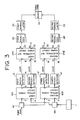
- Fig. 5 shows a graph of assistance in explaining a desirable state of polarization of the signal beam and the local-oscillator beam applied to the optical hybrid circuit shown in Fig. 4A or 4B included in the receiver shown in Fig. 1 or 2, in which the direction of light propagation coincides with that of the z-axis, the plane of polarization of a P-polarized beam divided by the polarizing splitter is included in the x-z plane and the plane of polarization of an S-polarized beam is included in the y-z plane of an orthogonal three-dimensional coordinate system, which applies also to Figs. 6 and 7.
- the state of polarization of the signal beam and that of the local-oscillator beam may be interchanged.
- the signal beam is a linearly polarized beam and the local-oscillator beam is a circularly polarized beam.
- circle of 70 is the projection of the locus of the tip of the field vector of the local-oscillator beam propagating in a circularly polarized beam on the x-y plane
- a line segment 72 is the projection of the locus of the extremity of the field vector of the signal beam propagating in a linearly polarized beam on the x-y plane.
- the local-oscillator beam 70 may be either a clockwise circularly polarized beam or a counterclockwise circularly polarized beam with respect to the direction of propagation.
- the signal beam 72 is a 45° linearly polarized beam having a plane of polarization inclined at an angle of 45° to the positive direction of the x-axis in a counterclockwise direction
- the branched signal beams divided by the polarizing splitter are equal to each other in power and hence optical powers that appear respectively at the first optical output port 6 and the second optical output port 8 are equal to each other to enhance the receiving sensitivity.
- a linearly polarized beam having a plane of polarization inclined at an angle of ⁇ ° to the positive direction of the x-axis in a counterclockwise direction will be designated as a ⁇ ° linearly polarized beam.
- the optical coupler 48 adds the local-oscillator beam 70 and the signal beam 72, and the polarizing splitter 50 splits the same.
- the phase shift between the split signal beams is zero, but the phase shift between the split local-oscillator beams is at the polarizing splitter 50.
- the 90°-shifted local-oscillator beams are added to the branched signal beams and the added beams are applied to the first optical output port 6 and the second optical output port 8.
- the optical hybrid circuit adds the 90°-shifted local-oscillator beams to the branched signal beams and applies the added beams respectively to the first optical output port 6 and the second optical output port 8 after performing light beam adding and light beam branching in order reverse to that in which the optical hybrid circuit shown in Fig. 4A performs the same.
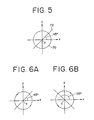
- Figs. 6A and 6B are graphs of assistance in explaining desirable states of polarization of a signal beam and a local-oscillator beam applied to the optical hybrid circuit shown in Figs. 4A and/or 4B included in a receiver shown in Fig. 3.
- a signal beam and a local-oscillator beam applied to either the first optical hybrid circuit 10A or the second optical hybrid circuit 10B are a 45° linearly polarized beam and a clockwise circularly polarized beam, as shown in Fig. 6A, respectively, a 135° linearly polarized beam and a clockwise circularly polarized beam as shown in Fig.
- the two optical hybrid circuits shift the phase of the local-oscillator beam in reverse directions, respectively.
- the phase of the local-oscillator beam added to the signal beam to be applied to the first optical port 6 of one of the two optical hybrid circuits is advanced by 90° relative to the phase of the local-oscillator beam added to the signal beam to be applied to the second optical output port 8 of the same optical hybrid circuit
- the phase of the local-oscillator beam added to the signal beam to be applied to the first optical output port 6 of the other optical hybrid circuit can be delayed by 90° relative to the local-oscillator beam added with the signal beam to be applied to the second optical output port 8 of the same optical hybrid circuit.
- a signal beam and a local-oscillator beam applied to one of the two optical hybrid circuits are a 45° linearly polarized beam and a clockwise circularly polarized beam as shown in Fig. 7A, respectively
- the respective phase shifting directions of the two optical hybrid circuits in shifting the phases of the local-oscillator beams applied respectively to the two optical hybrid circuits can be reverse to each other when a signal beam and a local-oscillator beam applied to the other optical hybrid circuit are a 45° linearly polarized beam and a counterclockwise circularly polarized beam as shown in Fig. 7B, respectively.
- the interference efficiency can be increased to a maximum by using linearly polarized beams having planes of polarization coinciding with each other as the input signal beam and the input local-oscillator beam and by maintaining the coincidence of the planes of polarization as far as the light receiving surfaces to increase the receiving sensitivity to a maximum.
- the phase shift produced by one of the phase shifters 66 is +90° when the phase shift produced by the other is -90° (+270°).
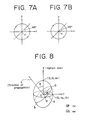
- the description made with reference to Figs. 5 to 7B is based on an assumption that the signal beam and the local-oscillator beam applied to the optical hybrid circuit shown in Fig. 4A or 4B are a linearly polarized beam and a circularly polarized beam, respectively, the signal beam and the local-oscillator beam applied respectively to the first optical input port 2 and the second optical input port 4 may be elliptically polarized beams, which will be described hereinafter with reference to Fig. 8.
- Fig. 8 shows an index ellipsoid of assistance in explaining circular polarization and elliptic polarization.
- a local-oscillator beam is emitted by a local light source, such as a laser diode, in a linearly polarized beam like the signal beam 72 shown in Fig. 5, the linearly polarized local-oscillator beam can be converted into a circularly polarized beam by using a quarter wavelength plate which functions at different refractive indices respectively with a polarized component having a plane of polarization included in the x-z plane and a polarized component having a plane of polarization included in the y-z plane.
- the quarter wavelength plate is a birefringent plate having a given thickness and disposed in a given crystal orientation.
- the refractive index of the birefringent plate with an ordinary beam is n o
- a maximum refractive index of the same with an extraordinary beam is n e (n o ⁇ n e )
- a light beam is traveling in the direction of an arrow S from the origin O of an orthogonal three-dimensional coordinate system having the z-axis coinciding with the optical axis of the birefringent plate, and the projection of the arrow S on the X-Y plane is included in the Y-axis.
- the refractive index n o with the ordinary beam is a constant corresponding to the distance OP between the origin O and a point P where a circle A obtained by intersecting the index ellipsoid with the X-Y plane intersects an ellipse B obtained by intersecting the index ellipsoid with a plane including the origin O and perpendicular to the direction S of propagation.
- the refractive index n e ′ with the extraordinary beam varies according to the angle ⁇ between the direction S of propagation and the Z-axis and corresponds to the distance OQ between the origin O and a point Q where the ellipse B intersects the Y-Z plane.
- the refractive index n e ′ with the extraordinary beam varies continuously between n o and n e according to the direction S of propagation.
- the input local-oscillator beam i.e., the linearly polarized beam
- an elliptically polarized beam having an appropriate ellipticity as either the signal beam or the local-oscillator beam, and an elliptically polarized beam having a corresponding ellipticity as the other beam, and to make the phase relation between the elliptically polarized beams correspond to the phase relation between a linearly polarized beam and a circularly polarized beam by utilizing the characteristics of the birefringent plate.
- DBORs dual-detector balanced optical receivers
- the DBOR shown in Fig. 9A amplifies voltage changes corresponding to photocurrent changes in two light receiving elements 74 and 76, such as pin photodiodes, having the same characteristics respectively by amplifiers 78 and 80, and applies the amplified voltage changes to subtracter 82 for subtraction.
- the respective optical path lengths of light beams incident on the light receiving elements 74 and 76 are adjusted, the respective phases of signal components falling on the light receiving elements 74 and 76 are opposite to each other and the respective phases of intensity noise components are the same due to the inversion of optical phase by the optical coupler. Accordingly, the signal components are added and the intensity noise components cancel each other to suppress the intensity noise of the local oscillator or the like.
- Figs. 10A, 10B and 10C are modifications of the optical hybrid circuits shown in Figs. 4A, 4B and 4C, respectively.
- An optical hybrid circuit shown in Fig. 10A is provided, in addition to the polarizing splitter 50 for splitting one of the beams branched by the optical coupler 48, a polarizing splitter 90 for splitting the other beam.
- P waves split by the polarizing splitters 50 and 90 are applied respectively to the optical output ports 6a and 6b of the first optical output 6.
- S waves split by the polarizing splitters 50 and 90 are applied to the optical output ports 8a and 8b of the second optical output port 8.
- the two P waves and the two S waves are applied through optical paths having appropriate optical path lengths respectively to the two light receiving elements 74 and 76, or 84 and 86 of the DBOR.
- An optical hybrid circuit shown in Fig. 10B branches each of added beams added by the optical couplers 56 and 58 into two branch beams.
- the optical outputs of the optical coupler 56 is applied to the optical output ports 6a and 6b of the first optical output port 6, and the optical outputs of the optical coupler 58 are applied to the optical output ports 8a and 8b of the second optical output port 8.
- An optical hybrid circuit shown in Fig. 10C similarly to that shown in Fig. 10B, applies the respective two optical outputs of two optical couplers 64 and 68 respectively to the first optical output port 6 and the second optical output port 86.
- the electrical 90° hybrid circuit 24 transmits a signal from the first electrical input port 16 to the first electrical output port 20 and from the second electrical input port 18 to the second electrical output port 22 at 3 dB loss without changing the phase of the signal, and transmits a signal from the first electrical input port 16 to the second electrical output port 22 and from the second electrical input port 18 to the first electrical output port at 3 dB loss changing the phase of the signal by 90°.
- the circuit configuration is changed according to the frequency band of the signal.
- the equalizers 26 and 28 may comprise, for example, a microstrip line or a slot line having a linear characteristic in a wide band.
- the circuit configurations of the demodulators 30 and 32 are determined on the basis of the principle of demodulation of 1-bit delay.
- E S C1 cos ( ⁇ S t + ⁇ ) (2)
- E S is the field intensity of the input signal beam
- C1 is an optional constant
- ⁇ S is the angular frequency of the carrier
- ⁇ is the phase difference between the electric field of the signal beam and that of the local-oscillator beam, which remains constant in one time slot (the reciprocal of bit rate).
- the signal beam is divided by the optical hybrid circuit 10 into two branch signal beams, the two branch signal beams are added to the local-oscillator beams of angular frequency having 90° phase difference, and the added beams are subjected to the square-law detection of the photodetectors 12 and 14.
- I4 sgn( ⁇ S - ⁇ L ) ⁇ sin ⁇ t (8)
- the electrical 90° hybrid circuit provides output signals in the upper sideband and those in the lower sideband separately, and hence signal degradation attributable to wavelength dispersion can be prevented by delaying the output signals according to their frequencies by the equalizers, which will be described below with reference to Figs. 11 to 13.
- the relation between the frequency f S of the signal beam and the frequency f L of the local-oscillator bed is f L ⁇ f S (Fig. 11A) or f S ⁇ f L (Fig. 11B).
- the upper sideband (continuous line) and lower sideband (broken line) of the output signals of the photodetectors 12 and 14 are folded as shown in Figs. 12A and 12B.
- Figs. 12A and 12B correspond respectively to Figs. 11A and 11B.
- the equalizer is unable to compensate the output signal of the photodetector directly, which is a previously describe problem in the general phase diversity system.
- the electrical 90° hybrid circuit 24 is able to provide the upper sideband signal and the lower sideband signal separately.
- the wavelength dispersion can be compensated by using an equalizer which gives greater delays for higher frequencies for the upper sideband signal, and an equalizer which gives smaller delays for higher signal frequencies for the lower sideband signal.
- the output signals O1 and O2 of the electrical 90° hybrid circuit 24 are an upper sideband signal and a lower sideband signal as shown in the table. Therefore, the respective characteristics of the equalizers 26 and 28 are reverse to each other.
- the receivers in the second and third embodiments of the present invention only the upper sideband signals O1 and O4 among the output signals of the first electrical 90° hybrid circuit 24A and the second electrical 90° hybrid circuit 24B are used, and hence the equalizers 26 and 28 are the same in characteristics.
- equalizers having the same characteristics which are reverse to those of the equalizers employed when the outputs O1 and O4 are used may be employed.
- the upper sideband signal and the lower sideband signal are separated from each other on a principle similar to an image rejection principle. Therefore, dispersion in each signal must be compensated by an equalizer to realize phase diversity. Accordingly, at least two equalizers are necessary.
- a receiver in a fourth embodiment of the present invention functions properly on a single equalizer.
- FIG. 14 is a block diagram of the receiver in the fourth embodiment according to the present invention.
- An optical local oscillator 1 comprises a light source (laser diode) 92 and a driving circuit 94 which drives the light source 92 by controlling the oscillation frequency through the control of the bias current supplied to the light source 92.
- the optical local oscillator 1 comprises further an optical hybrid circuit 10 and an electrical 90° hybrid circuit 24, which are similar to those of the first to third embodiments, respectively.
- the output signal of a photodetector 12 is added with the output signal of an oscillator by a mixer 98 for up-conversion and the added signal is applied to an electrical 90° hybrid circuit 24.
- the output signal of a photodetector 14 is added with the output signal of the oscillator 96 by a mixer 100 for up-conversion and the added signal is applied to the electrical 90° hybrid circuit 24.
- An output signal of the electrical 90° hybrid circuit 24 at a first electrical output port 20 is applied through an equalizer 26 to a demodulator 30.
- An output signal of the electrical 90° hybrid circuit 24 at a second electrical output port 24 is applied to a frequency discriminator 102.
- the oscillation frequency of the local oscillator 1 is controlled in a feedback control mode so that the frequency of the input signal to the frequency discriminator 102 is constant.
- the output photocurrents I1 and I2 of the photodetectors 12 and 14 are expressed by expressions (3) and (4).
- the two electrical signals obtained by optical detection are added by mixers 98 and 100 with the output current I of the oscillator 96 having an angular frequency ⁇ IF (» ⁇ OFF ).
- I C3 cos ⁇ IF t (17) where C3 is an optional constant.
- the output currents i1 and i2 of the mixers 98 and 100 are expressed by the following expressions, in which sgn( ⁇ S - ⁇ L ) is neglected for simplicity.
- the demodulator 30 is able to provide a baseband signal after applying the output current j1 to the equalizer 26 to compensate dispersion in the optical fiber.
- the receiver in the fourth embodiment is effective for the enhancement of transmission speed and realizes a phase diversity system not requiring a light source with a very narrow spectral line width.
- the receiver is capable of compensating dispersion in the optical fiber.
- the output currents j1 and j2 may be used respectively for the AFC of the optical local oscillator 1 and the baseband signal demodulation.
- the optical hybrid circuit comprising, in combination, the components respectively for particular functions, such as optical couplers
- a single device comprising a waveguide substrate carrying elements corresponding to all those components of the optical hybrid circuit to provide a compact receiver.
- Such a device provided with the light receiving elements of photodetectors directly formed on the waveguide substrate secures an accurate optical distance between the light receiving element and the optical coupler or the polarizing splitter to improve the reliability of the receiver.
Landscapes
- Physics & Mathematics (AREA)
- Electromagnetism (AREA)
- Engineering & Computer Science (AREA)
- Computer Networks & Wireless Communication (AREA)
- Signal Processing (AREA)
- Optical Communication System (AREA)
- Optical Modulation, Optical Deflection, Nonlinear Optics, Optical Demodulation, Optical Logic Elements (AREA)
Applications Claiming Priority (4)
| Application Number | Priority Date | Filing Date | Title |
|---|---|---|---|
| JP185906/89 | 1989-07-20 | ||
| JP1185906A JP2758215B2 (ja) | 1989-07-20 | 1989-07-20 | コヒーレント光通信用受信装置 |
| JP1206635A JP2758221B2 (ja) | 1989-08-11 | 1989-08-11 | コヒーレント光通信用受信装置 |
| JP206635/89 | 1989-08-11 |
Publications (3)
| Publication Number | Publication Date |
|---|---|
| EP0409260A2 true EP0409260A2 (fr) | 1991-01-23 |
| EP0409260A3 EP0409260A3 (en) | 1993-01-27 |
| EP0409260B1 EP0409260B1 (fr) | 1997-05-07 |
Family
ID=26503404
Family Applications (1)
| Application Number | Title | Priority Date | Filing Date |
|---|---|---|---|
| EP90113950A Expired - Lifetime EP0409260B1 (fr) | 1989-07-20 | 1990-07-20 | Récepteur pour communication optique cohérente |
Country Status (4)
| Country | Link |
|---|---|
| US (1) | US5115332A (fr) |
| EP (1) | EP0409260B1 (fr) |
| CA (1) | CA2021561C (fr) |
| DE (1) | DE69030634T2 (fr) |
Cited By (5)
| Publication number | Priority date | Publication date | Assignee | Title |
|---|---|---|---|---|
| FR2703201A1 (fr) * | 1993-03-26 | 1994-09-30 | Ericsson Telefon Ab L M | Système et procédé pour une compensation de la dispersion se produisant dans des systèmes à fibres optique à haut débit. |
| FR2704702A1 (fr) * | 1993-04-30 | 1994-11-04 | Ericsson Telefon Ab L M | Dispositif et procédé de compenssation de dispersion dans un sysstème de transmission à fibre optique. |
| EP1213858A3 (fr) * | 2000-11-28 | 2002-06-26 | AT&T Corp. | Systeme d'un recepteur de diversite a reduire la dispersion dans les fibres optiques par la detection separee de deux bandes laterales transmises |
| WO2002029456A3 (fr) * | 2000-10-02 | 2003-09-25 | Charles Romaniuk | Dispositif coupleur a quatre ports, a fonction de diviseur/combineur, dependant en phase |
| EP1209827A3 (fr) * | 2000-11-28 | 2004-05-06 | AT&T Corp. | Procédé pour un réçepteur de diversité pour reduire les effets de dispersion dans une fibre optique par détection séparée des deux bandes latérales |
Families Citing this family (39)
| Publication number | Priority date | Publication date | Assignee | Title |
|---|---|---|---|---|
| NL9100292A (nl) * | 1991-02-19 | 1992-09-16 | Nederland Ptt | Optisch zend- en ontvangsysteem met optische circulator. |
| US5532865A (en) * | 1992-10-09 | 1996-07-02 | Matsushita Electric Industrial Co., Ltd. | Fiber optic communication terminal, fiber optic communication system, and its wavelength setting method |
| US5473463A (en) * | 1993-05-13 | 1995-12-05 | Koninklijke Ptt Nederland N.V. | Optical hybrid |
| JPH08511929A (ja) * | 1994-04-12 | 1996-12-10 | フィリップス、エレクトロニクス、ネムローゼ、フェンノートシャップ | 低中間周波数を有するヘテロダイン受信機 |
| US5574589A (en) * | 1995-01-09 | 1996-11-12 | Lucent Technologies Inc. | Self-amplified networks |
| US5673133A (en) * | 1995-04-14 | 1997-09-30 | Nippon Telegraph And Telephone Corporation | Phase synchronization system |
| US6556326B2 (en) * | 1996-12-20 | 2003-04-29 | Tyco Telecommunications (Us) Inc. | Synchronous amplitude modulation for improved performance of optical transmission systems |
| US20040161245A1 (en) * | 1996-12-20 | 2004-08-19 | Bergano Neal S. | Synchronous amplitude modulation for improved performance of optical transmission systems |
| US6775484B1 (en) | 1997-06-03 | 2004-08-10 | Alcatel Alsthom Compagnie Generale D'electricite | Receiver for receiving optical signals |
| US7110677B2 (en) * | 2001-09-26 | 2006-09-19 | Celight, Inc. | Method and system for optical time division multiplexed fiber communications with coherent detection |
| US6473222B2 (en) | 2000-12-27 | 2002-10-29 | John N. Hait | Hyper-heterodyning, expanded bandpass apparatus and method |
| US6407848B1 (en) | 2000-12-27 | 2002-06-18 | All Optical Networks, Inc. | Servo-stabilized-phase, differential coherence detector |
| US7599627B2 (en) | 2001-05-31 | 2009-10-06 | Teradvance Communications, Llc | Method and system for a polarization mode dispersion tolerant optical homodyne detection system with optimized transmission modulation |
| US7945174B2 (en) * | 2001-09-26 | 2011-05-17 | Celight, Inc. | Secure optical communications system and method with coherent detection |
| JP3808820B2 (ja) * | 2002-10-08 | 2006-08-16 | 日本電信電話株式会社 | 光サンプリング方法、装置およびプログラム |
| US7460793B2 (en) * | 2002-12-11 | 2008-12-02 | Michael George Taylor | Coherent optical detection and signal processing method and system |
| US7054012B2 (en) * | 2003-06-09 | 2006-05-30 | Agilent Technologies, Inc | Spectral phase measurement using phase-diverse coherent optical spectrum analyzer |
| US7330669B2 (en) * | 2004-04-20 | 2008-02-12 | Lucent Technologies Inc. | Optical heterodyne receiver based on oversampling |
| RU2286019C2 (ru) * | 2004-09-23 | 2006-10-20 | Тамбовский военный авиационный инженерный институт | Способ обработки двоичных когерентных оптических сигналов в условиях шума спонтанного излучения и воздействия жесткой радиации и оптический приемник, реализующий способ |
| US7477852B2 (en) * | 2005-01-31 | 2009-01-13 | Alcatel-Lucent Usa Inc. | Optical receiver apparatus and method |
| US7650084B2 (en) * | 2005-09-27 | 2010-01-19 | Alcatel-Lucent Usa Inc. | Optical heterodyne receiver and method of extracting data from a phase-modulated input optical signal |
| US7406269B2 (en) * | 2006-03-10 | 2008-07-29 | Discovery Semiconductors, Inc. | Feedback-controlled coherent optical receiver with electrical compensation/equalization |
| US7835650B2 (en) * | 2006-07-11 | 2010-11-16 | Drexel University | Optical domain frequency down-conversion of microwave signals |
| CN101507149B (zh) * | 2006-09-26 | 2011-12-28 | 株式会社日立制作所 | 光场接收器以及光传输系统 |
| US8204378B1 (en) | 2008-03-27 | 2012-06-19 | Tektronix, Inc. | Coherent optical signal processing |
| US8213752B2 (en) * | 2008-06-09 | 2012-07-03 | Chapman David J | Coherent optical mixer and a method of coherent detection of light |
| KR20110030136A (ko) * | 2009-09-17 | 2011-03-23 | 한국전자통신연구원 | 편광 분리기, 광학 하이브리드 그리고 그것들을 포함하는 광 수신기 |
| JP5796934B2 (ja) * | 2010-04-13 | 2015-10-21 | 日本オクラロ株式会社 | 偏波ダイバーシティ光学系装置、復調器及び送受信機 |
| US8923707B2 (en) * | 2010-06-14 | 2014-12-30 | Infinera Corporation | Apparatus for compensating optical signal impairments |
| US8995836B2 (en) * | 2010-07-13 | 2015-03-31 | Futurewei Technologies, Inc. | Passive optical network with adaptive filters for upstream transmission management |
| CN102087421B (zh) * | 2010-12-03 | 2012-05-30 | 武汉光迅科技股份有限公司 | 用于相干光通信的晶体型光混合器 |
| WO2015023255A1 (fr) | 2013-08-12 | 2015-02-19 | Halliburton Energy Services, Inc | Systèmes et procédés de surveillance par capteur acoustique réparti à spectre étalé |
| US9337937B2 (en) | 2014-03-10 | 2016-05-10 | Cisco Technology, Inc. | Common mode rejection ratio control for coherent optical receivers |
| WO2016033192A1 (fr) * | 2014-08-28 | 2016-03-03 | Adelos, Inc. | Gestion de bruit pour interférométrie optique à retard temporel |
| WO2016161638A1 (fr) * | 2015-04-10 | 2016-10-13 | 华为技术有限公司 | Récepteur cohérent destiné à une estimation de décalage de fréquence et une compensation de source de lumière cohérente, procédé et système |
| US9768885B2 (en) * | 2015-09-10 | 2017-09-19 | Ut-Battelle, Llc | Pilot-aided feedforward data recovery in optical coherent communications |
| US10205535B1 (en) | 2017-12-14 | 2019-02-12 | Elenion Technologies, Llc | Coherent optical receiver |
| US11258594B2 (en) | 2018-11-21 | 2022-02-22 | Ut-Battelle, Llc | Quantum key distribution using a thermal source |
| CN112468162B (zh) * | 2021-02-02 | 2021-04-23 | 四川赛狄信息技术股份公司 | 双发万兆网中频信号处理机和双路径系统及数据传输方法 |
Family Cites Families (5)
| Publication number | Priority date | Publication date | Assignee | Title |
|---|---|---|---|---|
| US4723317A (en) * | 1986-05-08 | 1988-02-02 | American Telephone And Telegraph Company, At&T Bell Laboratories | Optical heterodyne mixers providing image-frequency rejection |
| US4723316A (en) * | 1986-05-08 | 1988-02-02 | American Telephone & Telegraph Company, At&T Bell Laboratories | Polarization independent coherent optical heterodyne receivers |
| US4718120A (en) * | 1986-11-24 | 1988-01-05 | American Telephone And Telegraph Company, At&T Bell Laboratories | Polarization insensitive coherent lightwave detector |
| JP2562623B2 (ja) * | 1987-10-28 | 1996-12-11 | 国際電信電話株式会社 | ベースバンド合成法による偏波ダイバーシティ光受信方式 |
| JP2658180B2 (ja) * | 1988-05-20 | 1997-09-30 | 日本電気株式会社 | 偏波ダイバーシチ光受信装置 |
-
1990
- 1990-07-18 US US07/553,744 patent/US5115332A/en not_active Expired - Lifetime
- 1990-07-19 CA CA002021561A patent/CA2021561C/fr not_active Expired - Fee Related
- 1990-07-20 EP EP90113950A patent/EP0409260B1/fr not_active Expired - Lifetime
- 1990-07-20 DE DE69030634T patent/DE69030634T2/de not_active Expired - Fee Related
Cited By (7)
| Publication number | Priority date | Publication date | Assignee | Title |
|---|---|---|---|---|
| FR2703201A1 (fr) * | 1993-03-26 | 1994-09-30 | Ericsson Telefon Ab L M | Système et procédé pour une compensation de la dispersion se produisant dans des systèmes à fibres optique à haut débit. |
| FR2704702A1 (fr) * | 1993-04-30 | 1994-11-04 | Ericsson Telefon Ab L M | Dispositif et procédé de compenssation de dispersion dans un sysstème de transmission à fibre optique. |
| US5522004A (en) * | 1993-04-30 | 1996-05-28 | Telefonaktiebolaget Lm Ericsson | Device and method for dispersion compensation in a fiber optic transmission system |
| WO2002029456A3 (fr) * | 2000-10-02 | 2003-09-25 | Charles Romaniuk | Dispositif coupleur a quatre ports, a fonction de diviseur/combineur, dependant en phase |
| EP1213858A3 (fr) * | 2000-11-28 | 2002-06-26 | AT&T Corp. | Systeme d'un recepteur de diversite a reduire la dispersion dans les fibres optiques par la detection separee de deux bandes laterales transmises |
| EP1209827A3 (fr) * | 2000-11-28 | 2004-05-06 | AT&T Corp. | Procédé pour un réçepteur de diversité pour reduire les effets de dispersion dans une fibre optique par détection séparée des deux bandes latérales |
| US6959154B1 (en) | 2000-11-28 | 2005-10-25 | At&T Corp. | Diversity receiver for mitigating the effects of fiber dispersion by separate detection of the two transmitted sidebands |
Also Published As
| Publication number | Publication date |
|---|---|
| US5115332A (en) | 1992-05-19 |
| EP0409260B1 (fr) | 1997-05-07 |
| DE69030634T2 (de) | 1997-10-02 |
| CA2021561A1 (fr) | 1991-01-21 |
| CA2021561C (fr) | 1994-01-11 |
| DE69030634D1 (de) | 1997-06-12 |
| EP0409260A3 (en) | 1993-01-27 |
Similar Documents
| Publication | Publication Date | Title |
|---|---|---|
| EP0409260B1 (fr) | Récepteur pour communication optique cohérente | |
| US5003626A (en) | Dual balanced optical signal receiver | |
| CN110233675B (zh) | 多功能微波光子模块及基于其的信号处理方法、装置 | |
| US5060312A (en) | Polarization independent coherent lightwave detection arrangement | |
| JP3001943B2 (ja) | 偏波スイッチング光源、光受信装置及びコヒーレント光伝送システム | |
| CN109150314B (zh) | 变频移相一体化光子微波混频装置 | |
| US4506388A (en) | Process and apparatus for the coherent detection and demodulation of a phase-modulated carrier wave in a random polarization state | |
| US5424863A (en) | Dual-polarization fiber optic communications link | |
| US20120288286A1 (en) | Optical receiver for amplitude-modulated signals | |
| JPS63500067A (ja) | コヒ−レント光信号受信装置 | |
| US5146359A (en) | Double-stage phase-diversity receiver | |
| JPH0478251A (ja) | コヒーレント光通信用偏波ダイバーシティ受信装置 | |
| CN108736978A (zh) | 一种反射式相干光通信系统发射端 | |
| US3214590A (en) | Communication receiver utilizing negative feedback polarization modulation of electromagnetic waves and communication system including said receiver | |
| US5140453A (en) | Optical receiving method utilizing polarization diversity and apparatus for carrying out the same | |
| JPS62272234A (ja) | 光ヘテロダイン・ミキサ | |
| US7269354B1 (en) | Superheterodyne photonic receiver using non-serial frequency translation | |
| CN113992274A (zh) | 硅基集成高精度射频信号稳相传输芯片、发送端及系统 | |
| US5317382A (en) | Optical phase detection method with orthogonal polarization and phase compensation arrangement | |
| EP0260745A1 (fr) | Dispositif de détection optique hétérodyne d'un signal optique et système de transmission optique muni d'un tel dispositif | |
| JPH05158096A (ja) | コヒーレント光波通信用光受信機 | |
| JP2758221B2 (ja) | コヒーレント光通信用受信装置 | |
| Lin et al. | Microwave photonics reconfigurable mixer based on polarization modulator | |
| JP2760856B2 (ja) | マッハツェンダ型光変調器を用いた位相シフトキーイング方式 | |
| CN115542565A (zh) | 一种偏振不敏感的90°空间光混频器 |
Legal Events
| Date | Code | Title | Description |
|---|---|---|---|
| PUAI | Public reference made under article 153(3) epc to a published international application that has entered the european phase |
Free format text: ORIGINAL CODE: 0009012 |
|
| AK | Designated contracting states |
Kind code of ref document: A2 Designated state(s): DE FR GB |
|
| PUAL | Search report despatched |
Free format text: ORIGINAL CODE: 0009013 |
|
| 17P | Request for examination filed |
Effective date: 19921021 |
|
| AK | Designated contracting states |
Kind code of ref document: A3 Designated state(s): DE FR GB |
|
| 17Q | First examination report despatched |
Effective date: 19941201 |
|
| GRAG | Despatch of communication of intention to grant |
Free format text: ORIGINAL CODE: EPIDOS AGRA |
|
| GRAH | Despatch of communication of intention to grant a patent |
Free format text: ORIGINAL CODE: EPIDOS IGRA |
|
| GRAH | Despatch of communication of intention to grant a patent |
Free format text: ORIGINAL CODE: EPIDOS IGRA |
|
| GRAA | (expected) grant |
Free format text: ORIGINAL CODE: 0009210 |
|
| AK | Designated contracting states |
Kind code of ref document: B1 Designated state(s): DE FR GB |
|
| RIN1 | Information on inventor provided before grant (corrected) |
Inventor name: KUWAHARA, HIDEO Inventor name: ONODA, YOSHIHITO Inventor name: KIYONAGA, TETSUYA Inventor name: NAITO, TAKAO Inventor name: WATANABE, SHIGEKI Inventor name: CHIKAMA, TERUMI |
|
| REF | Corresponds to: |
Ref document number: 69030634 Country of ref document: DE Date of ref document: 19970612 |
|
| ET | Fr: translation filed | ||
| PLBE | No opposition filed within time limit |
Free format text: ORIGINAL CODE: 0009261 |
|
| STAA | Information on the status of an ep patent application or granted ep patent |
Free format text: STATUS: NO OPPOSITION FILED WITHIN TIME LIMIT |
|
| 26N | No opposition filed | ||
| REG | Reference to a national code |
Ref country code: GB Ref legal event code: IF02 |
|
| PGFP | Annual fee paid to national office [announced via postgrant information from national office to epo] |
Ref country code: FR Payment date: 20050708 Year of fee payment: 16 |
|
| PGFP | Annual fee paid to national office [announced via postgrant information from national office to epo] |
Ref country code: DE Payment date: 20050714 Year of fee payment: 16 |
|
| PGFP | Annual fee paid to national office [announced via postgrant information from national office to epo] |
Ref country code: GB Payment date: 20050720 Year of fee payment: 16 |
|
| PG25 | Lapsed in a contracting state [announced via postgrant information from national office to epo] |
Ref country code: GB Free format text: LAPSE BECAUSE OF NON-PAYMENT OF DUE FEES Effective date: 20060720 |
|
| PG25 | Lapsed in a contracting state [announced via postgrant information from national office to epo] |
Ref country code: DE Free format text: LAPSE BECAUSE OF NON-PAYMENT OF DUE FEES Effective date: 20070201 |
|
| GBPC | Gb: european patent ceased through non-payment of renewal fee |
Effective date: 20060720 |
|
| REG | Reference to a national code |
Ref country code: FR Ref legal event code: ST Effective date: 20070330 |
|
| PG25 | Lapsed in a contracting state [announced via postgrant information from national office to epo] |
Ref country code: FR Free format text: LAPSE BECAUSE OF NON-PAYMENT OF DUE FEES Effective date: 20060731 |