EP0410231A1 - Procédé de maintien d'une qualité de ruban donnée dans une carde et/ou une machine d'étirage - Google Patents
Procédé de maintien d'une qualité de ruban donnée dans une carde et/ou une machine d'étirage Download PDFInfo
- Publication number
- EP0410231A1 EP0410231A1 EP90113426A EP90113426A EP0410231A1 EP 0410231 A1 EP0410231 A1 EP 0410231A1 EP 90113426 A EP90113426 A EP 90113426A EP 90113426 A EP90113426 A EP 90113426A EP 0410231 A1 EP0410231 A1 EP 0410231A1
- Authority
- EP
- European Patent Office
- Prior art keywords
- card
- sliver
- production
- throttling
- cans
- Prior art date
- Legal status (The legal status is an assumption and is not a legal conclusion. Google has not performed a legal analysis and makes no representation as to the accuracy of the status listed.)
- Ceased
Links
Images


Classifications
-
- D—TEXTILES; PAPER
- D01—NATURAL OR MAN-MADE THREADS OR FIBRES; SPINNING
- D01G—PRELIMINARY TREATMENT OF FIBRES, e.g. FOR SPINNING
- D01G21/00—Combinations of machines, apparatus, or processes, e.g. for continuous processing
Definitions
- the invention relates to a method for maintaining a predetermined sliver quality of a sliver produced or stretched in a card and / or draw frame, which is put into a can by a sliver deposition, in a continuous working process of a spinning mill.
- the machine types before and after the spinning machine are designed so that they have an excess of power compared to the spinning machine, so that neither the spinning machine has to wait for the delivery of its basic product nor for further processing, for example in a winder.
- the task of the inventor was therefore to optimize the performance levels in the aforementioned blow room of a spinning mill in such a way that, on the one hand, the smallest possible buffers were necessary for the intermediate products and, on the other hand, automation was made possible.
- the object was achieved according to the invention in that the card and / or the draw frame, which each have a predetermined additional production compared to a spinning machine belonging to the working process, has a predetermined temporary production throttling, which compensates for the additional production accordingly temporarily.
- a card with a tape reel for carrying out the method, which is characterized in that the card control has a computer part which, when the production throttling is switched on, has the predetermined deceleration and, if appropriate, the stopping, and when the production has been switched off the predetermined acceleration and, before that, the restart carries out and that between the card and the sliver a belt sag monitoring controls the deceleration, if necessary also the stopping and restarting and the acceleration of the sliver.
- a route is also proposed for carrying out the method, which is characterized in that the route control has a computer part which, when the production throttling is switched on, carries out the predetermined deceleration and, if necessary, stops, and when the production throttling is switched off, the predetermined acceleration and, if necessary, the restart.
- a combined card and draw system is also proposed for carrying out the method, which is characterized in that the draw system has a can supply and in this set of cans has a row of cans with a can counter and that the can counter, with a predetermined number of cans in the Row that emits a signal.
- the advantage of the invention is that it provides a basis for optimizing economy and a possibility for automation.
- Figure 1 shows an efficiency diagram of some spinning machines, in which the 100% efficiency is shown with the dash-dotted line W and in which the downtimes of the individual machines (purely schematically) are shown with the distance arrows DP, DK, DST, DF, DR and DSP.
- the letters in the hatched rectangles mean the following:
- the letter P means blow room machines
- the letter K means cards
- the letter ST means stretches
- the letter F means flyer
- the letter R means ring spinning machines
- the letter SP means winding machines
- the rectangles containing the letters P to SP represent the machine outputs purely schematically and their areas are selected such that the area of the next machine type is smaller than that of the previous one with the exception of the area for the winding machines, which is again larger than that of the ring spinning machines . This is to visualize the reduction in performance from the blowroom machines up to and including the ring spinning machine, these surfaces for better visualization of the differences with exaggerated differences are shown. Likewise, the areas shown are not actually related to the downtime, which is also shown with greater differences for clarification than is usually the case in practice.
- the carding machine is the most complex of machine types P to F, i.e. a machine in which a large number of technical and technological functions have to work together in order to produce a uniform and high-quality card sliver.
- the method according to the invention provides that if the card output is throttled, the card continues to produce with normal output until a change of can is required and shortly after such a can change, the card is switched to the reduced output either until the card comes to a standstill or until production continues at a minimum output level.
- the throttling occurs with a delay, as shown by line 1 in Figure 1.
- the card is throttled to a standstill in order to bring it back to full power after a controlled time T, which is shown by lines 2a and 2b, this acceleration being identified by line 3.
- the dash-dotted lines show the switching torque for the can change, namely the dash-dotted line 4 the switching torque before throttling 1 and the line 5 the switching torque for the new can change after acceleration 3, in order to then deposit the sliver produced at full power in the next can.
- FIG. 3 shows the same principle, with the difference that the output was not reduced to zero as in FIG. 2, but that the carding machine continues to produce with a very low output, for example one tenth of the normal output, until the control command for renewed acceleration is given becomes.
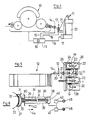
- FIG. 4 shows a cross-section of a card 10 known per se with a band deposit 11 known per se and an intervening band loop scanning 12 known per se.
- the card is a card manufactured by the applicant and sold worldwide with the designation C4 / 1, and the tape holder 11 including tape loop scanning 12 is sold worldwide by the applicant under the designation CBA.
- the two combined machines are, for example, demonstrated to the public at the American textile machine exhibition ATME 1989 in Greenville.
- the card 10, as well as the tape reel 11, functions with the aid of a control 13, which on the one hand dictates to the card the signals necessary for the power and the tape reel 11 a tape reel output corresponding to the card output, which is activated with the help of the tape loop control 12 depending on the change in performance of the card 10 the change in performance of the card is adjusted.
- the card sliver output that is to say the card sliver mass produced in one unit of time, is measured by means of a pair of measuring rollers 14 at the card output and communicated to the controller 13 with a measuring pulse 15. From this, the controller 13 deduces a power signal 16 which controls the drive motor 17 of the tape storage 11.
- control 13 has a computer add-on, which is shown purely schematically at 19 and which, when a switch described later is actuated, throttles the performance of the card either in accordance with the diagram in FIG. 2 or in FIG. 3 and when the same switch is actuated again in accordance with FIGS accelerates the aforementioned two figures.
- the throttling as well as the acceleration causes a change in the position of the sliver loop 20 of the sliver 21, which is produced by the card 10 and is deposited by the sliver holder 11 into a can 22.
- This change in position of the tape loop 20 causes corresponding signals 18, so that the tape storage 11 or. whose motor 17 either throttles or accelerates the tape storage accordingly. In this way, there is the advantage that no additional synchronization between the motors of the card and the drive motor 17 of the tape holder 11 is required.
- FIG. 5 shows a top view of the card 10 and the tape holder 11 and the tape loop scanner 12.
- the tape holder 11 is already known from the publication. What is new according to the invention is that the incoming empty cans are conveyed with a conveyor belt 23 to an initial position M, in which a sliding arm 24 of the can displacement device 25 brings the can into the belt depositing position N, in which sliver is filled into the can.
- the can filled with ordinary sliver is moved into a first pick-up position by a second shift arm 26 T is moved onto a conveyor belt 27, while a can, into which a fiber belt with reduced power is filled, is moved into a further second pick-up position Q onto a conveyor belt 28.
- These functions are controlled by the computer part 19.
- These sliding arms can be pivoted (not shown) in such a way that they are pivoted from a vertical position in which they can be moved past the standing cans into a horizontal position in order to carry out the displacement of the cans in this position.
- These swivel arms are part of the tape storage 11.
- FIG. 6 shows a number of cards 12 which are arranged parallel to one another in such a way that the conveyor belts 23, 27 and 28 open out against a can conveyor 29.
- the cans standing on the conveyor belts are shifted according to the arrows shown in FIGS. 5 and 6, that is to say the cans on the conveyor belt 23 in the direction of the can deposit and the cans on the conveyor belts 27 and 28 in the direction of the can conveyor means 29.
- the cans on the conveyor belt 23 are empty cans and the cans on the conveyor belt 27 are full cans, while the conveyor belt 28 conveys those cans which contain the sliver which was produced with throttled output of the card, so that a can can have any filling level.
- the can conveyor 29 has pneumatic cylinder-piston units 30.
- These cylinder-piston units are shown in more detail in FIG . It can be seen from this that these units have a suction and sliding shoe 31 that is adapted to the can diameter of the cans 22 include, which has an air-permeable but plastically deformable wall 32 which is adapted to the can diameter and which covers a hollow body 33 which extends by means of a bore 34 through the piston rod 35 and through the piston 36, so that the cavity 37 is connected to the pressure chamber 38 of the cylinder 39 is.
- the bore 34 is provided at the end on the pressure chamber side with a non-return flap 40 which functions in such a way that if the pressure chamber 38 is in excess pressure by means of a compressed air valve 41 connected to the pressure chamber 38, the flap 40 then closes off the bore 34, so that the piston 36 and thus the shoe 31 can also be moved in the direction of the arrow 42.
- the suction air valve 43 is connected to a suction air source 45 and the compressed air valve 41 to a compressed air source 46.
- empty cans are pushed from the can conveyor 29 onto the conveyor belt 23 and full cans from The conveyor belt 27 is pulled onto the conveyor 29, as are the cans from the conveyor belt 28.
- the can conveyor 29 is provided to be movable on rails 47.
- a control station which allows this can conveyor 29 to be moved is shown schematically with a rectangle, which is identified by 48, and is the subject of an application by the applicant with the number CH 0 4410 / 88-1 and is not further described here.
- a section 50 Adjacent to the rails 47 and on a side of the rail oval shown in FIG. 6 opposite the cards, a section 50 is provided which takes over the cans filled by the cards 12 and processes their sliver. Such a route is known per se and is marketed worldwide, for example, by the applicant under the designation D1.
- the draw frame part 51 which stretches the fiber slivers 53 fed on an infeed table 52, is part of the draw frame.
- the slivers 53 are discharged from the can row 54 in which there are emptying cans.
- the can row 55 arranged parallel to the can row 54 consists of full cans which are in the reserve position.
- the next parallel row of cans 56 arranged above it, as seen in FIG. 6, is also a row with full cans, but a row which is in the process of receiving full cans from the can conveyor 29.
- the cans of the row 56 can be moved on the one hand in the conveying direction 58 and on the other hand in the conveying direction 59.
- the displacement in the conveying direction 58 is accomplished by individual conveyor belts 60 lined up, while the displacement of the cans 22 in the conveying direction 59 is carried out by cylinder piston units 30. These cylinder-piston units 30 shift the cans 22 from the row 56 into the row 55.
- Conveyor belts 60 are provided for the displacement of the cans 22 in the rows 55 and 54, which, however, are rotated by 90 ° in relation to the conveyor belts of the row 56, so that the cans are moved in the conveying direction 59.
- the cans emptied in the row 54 are moved under the infeed table by means of a further row of conveyor belts, which move the cans in the conveying direction 59 to such an extent that the cans can be pulled onto the conveyor belts of the row 57 by further cylinder-piston units 30 .
- the cans are moved in the conveying direction 61 on these conveyor belts, so that these cans can be transported against the can conveyor 29.
- a single conveyor belt (not shown) can be used.
- Moving the cans into the next row happens when the cans in row 54 are empty, which is indicated by a belt sensor (not shown) on the infeed table, for example on the Deflections 91, which deflect the fiber sliver by 90 °, are determined and input into a controller 63 as signal 92 (not shown completely).
- This control causes the conveyor belts and cylinder units which move the cans in the direction 59 to be actuated, that is to say the conveyor belts 55, 54 and 62 as well as the cylinder units 30, for pushing as well as for pulling the cans.
- the timely shifting of the cans in the path 50 is also accomplished by the controller 63, that is to say the change of the full cans to empty cans, which is done essentially in the same way as described for the cards 12 and with corresponding arrow directions is shown.
- the actual drafting unit part 51 of the line 50 is also controlled for the stop-start operation as well as for the throttled operation by means of an associated computer part.
- a can conveying means 29.1 is also provided for the route 50 in the same way as for the cards 12, which has the same function as the conveying means 29, but it becomes the full and empty cans for the route of the subsequent machine, for example a flyer or a plurality of flyers promote.
- the cans already described which contain sliver that was produced during the performance throttling of the cards 12 and which are fed to the conveyor 29 by the conveyor belt 28, are delivered by the conveyor 29 into a supply row 70 which the cans in the conveying direction 71 by means of a conveyor belt moves so that they can be picked up by other means, not shown, and conveyed to a disposal station (not shown).
- Empty cans come back from this disposal station and are entered into a supply row 72, which likewise consists of a conveyor belt, but which is operated in such a way that the empty cans can be moved in the direction of displacement 73 against the can conveyor 29 and can be delivered to the latter.
- the can shifting organization for the section 50 corresponds essentially to that described for the cards 12, which is why it is not shown and described again. The same applies to the readiness for full and empty cans, which sliver included, which is not of the quality that is normally processed, so that this sliver is disposed of in the above-mentioned disposal station.
- a can sensor is provided in the row 56, which announces the number of cans in the row by means of a signal 80 from the control station 48.
Landscapes
- Engineering & Computer Science (AREA)
- Textile Engineering (AREA)
- Spinning Or Twisting Of Yarns (AREA)
- Preliminary Treatment Of Fibers (AREA)
Applications Claiming Priority (2)
| Application Number | Priority Date | Filing Date | Title |
|---|---|---|---|
| CH278889 | 1989-07-26 | ||
| CH2788/89 | 1989-07-26 |
Publications (1)
| Publication Number | Publication Date |
|---|---|
| EP0410231A1 true EP0410231A1 (fr) | 1991-01-30 |
Family
ID=4241606
Family Applications (1)
| Application Number | Title | Priority Date | Filing Date |
|---|---|---|---|
| EP90113426A Ceased EP0410231A1 (fr) | 1989-07-26 | 1990-07-13 | Procédé de maintien d'une qualité de ruban donnée dans une carde et/ou une machine d'étirage |
Country Status (4)
| Country | Link |
|---|---|
| US (2) | US5067202A (fr) |
| EP (1) | EP0410231A1 (fr) |
| JP (1) | JPH0359117A (fr) |
| DD (1) | DD295675A5 (fr) |
Families Citing this family (8)
| Publication number | Priority date | Publication date | Assignee | Title |
|---|---|---|---|---|
| CH681632A5 (fr) * | 1990-02-21 | 1993-04-30 | Rieter Ag Maschf | |
| DE4219777A1 (de) * | 1992-06-17 | 1993-12-23 | Rieter Ingolstadt Spinnerei | Verfahren und Vorrichtung zur Signalanalyse einer Regulierstrecke |
| US5400476A (en) * | 1994-07-12 | 1995-03-28 | Myrick-White, Inc. | Apparatus and method for controlling draft uniformity in textile sliver |
| DE4428476A1 (de) * | 1994-08-11 | 1996-02-15 | Truetzschler Gmbh & Co Kg | Verfahren und Vorrichtung zum Ablegen eines Textilfaserbandes in einer Faserbandkanne, insbesondere an einer Strecke |
| DE69500919T2 (de) * | 1994-11-29 | 1998-06-10 | M & M Electric Service Co Inc | Festkörper-Faserbandsensor |
| DE19721758B4 (de) * | 1996-06-29 | 2010-12-02 | TRüTZSCHLER GMBH & CO. KG | Vorrichtung an einer Karde, bei der am Ausgang der Karde ein Flortrichter mit Abzugswalzen vorhanden ist |
| CN105274683A (zh) * | 2015-10-10 | 2016-01-27 | 安徽荣业纺织有限公司 | 一种棉纺织加工工艺 |
| CN107217341B (zh) * | 2017-07-03 | 2023-06-09 | 倪天立 | 一种适合羊绒的精梳机出条电子控制系统 |
Citations (4)
| Publication number | Priority date | Publication date | Assignee | Title |
|---|---|---|---|---|
| US3703023A (en) * | 1969-06-24 | 1972-11-21 | Zinser Textilmaschinen Gmbh | Apparatus for rendering textile slivers uniform |
| US3862473A (en) * | 1971-12-22 | 1975-01-28 | Zellweger Uster Ag | Control of the filling level of silver reservoirs in the textile industry |
| US4019225A (en) * | 1973-01-29 | 1977-04-26 | Nayfa James E | Mill fiber treatment apparatus |
| EP0220945A2 (fr) * | 1985-10-25 | 1987-05-06 | Howa Machinery Limited | Installation de filature continue pour connecter plusieurs machines de cardage à une étireuse |
Family Cites Families (13)
| Publication number | Priority date | Publication date | Assignee | Title |
|---|---|---|---|---|
| CA587418A (fr) * | 1959-11-17 | Rockwool Aktiebolaget | Commande de vitesse de convoyeur dans la formation de nattes | |
| JPS5022626B2 (fr) * | 1972-10-19 | 1975-08-01 | ||
| EP0038927B2 (fr) * | 1980-03-28 | 1989-05-17 | Maschinenfabrik Rieter Ag | Procédé et dispositif pour la régulation des fluctuations du titre d'un ruban de fibres |
| DE3133438C2 (de) * | 1981-08-24 | 1983-11-03 | Heberlein Hispano S.A., 1214 Vernier-Genève | Verfahren und Vorrichtung zum automatischen Wechsen gefüllter Kannen gegen leere Kannen an einer Doppelkopfstrecke |
| IN158614B (fr) * | 1982-04-01 | 1986-12-27 | Truetzschler & Co | |
| DE3505495A1 (de) * | 1985-02-16 | 1986-08-21 | W. Schlafhorst & Co, 4050 Mönchengladbach | Verfahren und vorrichtung zum austauschen leerer kannen gegen mit faserband gefuellte kannen |
| IN165584B (fr) * | 1985-09-10 | 1989-11-25 | Truetzschler & Co | |
| DE3532172A1 (de) * | 1985-09-10 | 1987-03-12 | Truetzschler & Co | Vorrichtung zum automatischen transport mindestens einer kanne zwischen einer faserbandabliefernden spinnereimaschine und einer faserbandgespeisten spinnereimaschine |
| EP0312805B1 (fr) * | 1987-10-07 | 1991-11-21 | Maschinenfabrik Rieter Ag | Commande de production |
| DE3803353A1 (de) * | 1988-02-05 | 1989-08-17 | Truetzschler & Co | Vorrichtung zur gewinnung von messgroessen, die der dicke von in der spinnereivorbereitung anfallenden faserverbaenden, z.b. kardenbaendern o. dgl. entsprechen |
| US4823597A (en) * | 1988-06-06 | 1989-04-25 | Myrick-White, Inc. | Sliver measuring apparatus |
| CH677782A5 (fr) * | 1988-11-28 | 1991-06-28 | Rieter Ag Maschf | |
| DE3905279A1 (de) * | 1989-02-21 | 1990-08-23 | Zinser Textilmaschinen Gmbh | Kannentransportsystem strecke/strecke |
-
1990
- 1990-07-09 US US07/549,756 patent/US5067202A/en not_active Expired - Fee Related
- 1990-07-13 EP EP90113426A patent/EP0410231A1/fr not_active Ceased
- 1990-07-24 DD DD90343039A patent/DD295675A5/de not_active IP Right Cessation
- 1990-07-25 JP JP2195080A patent/JPH0359117A/ja active Pending
-
1991
- 1991-08-09 US US07/743,092 patent/US5274884A/en not_active Expired - Fee Related
Patent Citations (4)
| Publication number | Priority date | Publication date | Assignee | Title |
|---|---|---|---|---|
| US3703023A (en) * | 1969-06-24 | 1972-11-21 | Zinser Textilmaschinen Gmbh | Apparatus for rendering textile slivers uniform |
| US3862473A (en) * | 1971-12-22 | 1975-01-28 | Zellweger Uster Ag | Control of the filling level of silver reservoirs in the textile industry |
| US4019225A (en) * | 1973-01-29 | 1977-04-26 | Nayfa James E | Mill fiber treatment apparatus |
| EP0220945A2 (fr) * | 1985-10-25 | 1987-05-06 | Howa Machinery Limited | Installation de filature continue pour connecter plusieurs machines de cardage à une étireuse |
Also Published As
| Publication number | Publication date |
|---|---|
| JPH0359117A (ja) | 1991-03-14 |
| US5274884A (en) | 1994-01-04 |
| US5067202A (en) | 1991-11-26 |
| DD295675A5 (de) | 1991-11-07 |
Similar Documents
| Publication | Publication Date | Title |
|---|---|---|
| DE69601575T3 (de) | Lagereinheit zum speichern von halbfertigen produkten mit geschwindigkeitsregelung | |
| DE68904250T2 (de) | Verfahren zum ergreifen und einfuehren eines vorgarns in open-end-spinnvorrichtungen und einrichtung zur durchfuehrung dieses verfahrens. | |
| CH643604A5 (de) | Kops- und spulenfoerdervorrichtung. | |
| EP0311831B1 (fr) | Régulation des étapes d'ouverture de fibres d'une installation de préparation à la filature | |
| WO2008043408A1 (fr) | Poste de travail d'une machine pour textile | |
| EP1009870B2 (fr) | Banc d'etirage regule | |
| DE102004017441B4 (de) | Verfahren zur Faserverbundtrennung sowie Spinnereivorbereitungsmaschine | |
| EP0410231A1 (fr) | Procédé de maintien d'une qualité de ruban donnée dans une carde et/ou une machine d'étirage | |
| DE4424490A1 (de) | Strecke und Verfahren zum Betrieb einer Strecke | |
| CH691485A5 (de) | Verfahren und Vorrichtung zum Füllen von Kannen mit länglichem Querschnitt an einer Spinnereimaschine. | |
| EP0401162B1 (fr) | Machine de peignage | |
| EP3677711A1 (fr) | Procédé de fonctionnement d'un métier à filer et métier à filer | |
| DE102013009998A1 (de) | Verfahren zum Betreiben einer Arbeitsstelle einer Offenend-Rotorspinnmaschine sowie zugehörige Arbeitsstelle | |
| WO2004099052A1 (fr) | Procede pour façonner des rubans de fibres dans un atelier de peignage, support de pots pour machine a peigner et machine a peigner | |
| CH684836A5 (de) | Verfahren zur Steuerung der Arbeitsabläufe zwischen einem Bedienungsautomaten und einer Spinnstelle einer Textilmaschine. | |
| WO1998032903A1 (fr) | Carde avec systeme d'etirage a la decharge | |
| DE2310607A1 (de) | Verfahren und vorrichtung zur erzielung von gleichmaessigem fasergut zum spinnen | |
| DE3144760C2 (de) | Verfahren und Vorrichtung zum Steuern des Anspinnvorgangs bei einer Offenend-Rotorspinnmaschine | |
| DE102016110897A1 (de) | Spinnereivorbereitungsmaschine in Form einer Strecke sowie Verfahren zum Betreiben einer solchen | |
| CH217448A (de) | Verfahren und Vorrichtung zum Herstellen von Vorgarn. | |
| DE102020110991A1 (de) | Verfahren zum Trennen eines aus einer Spinnkanne an eine Spinnstelle einer Spinnmaschine gelieferten Faserbandes sowie Spinnmaschine | |
| EP0754253A1 (fr) | Systeme d'entrainement synchronise de plusieurs arbres de machines de peignage | |
| DE102004044551B4 (de) | Verfahren zum Betrieb einer Spinnmaschine sowie Spinnmaschine zur Ausführung dieses Verfahrens | |
| EP0093235A1 (fr) | Procédé pour ouvrir des balles de fibres | |
| CH676837A5 (fr) |
Legal Events
| Date | Code | Title | Description |
|---|---|---|---|
| PUAI | Public reference made under article 153(3) epc to a published international application that has entered the european phase |
Free format text: ORIGINAL CODE: 0009012 |
|
| AK | Designated contracting states |
Kind code of ref document: A1 Designated state(s): CH DE ES FR GB IT LI |
|
| 17P | Request for examination filed |
Effective date: 19901221 |
|
| 17Q | First examination report despatched |
Effective date: 19920709 |
|
| STAA | Information on the status of an ep patent application or granted ep patent |
Free format text: STATUS: THE APPLICATION HAS BEEN REFUSED |
|
| 18R | Application refused |
Effective date: 19950406 |