EP0410281A2 - Commutateur à bouton poussoirs ou commutateur à touche - Google Patents
Commutateur à bouton poussoirs ou commutateur à touche Download PDFInfo
- Publication number
- EP0410281A2 EP0410281A2 EP90113722A EP90113722A EP0410281A2 EP 0410281 A2 EP0410281 A2 EP 0410281A2 EP 90113722 A EP90113722 A EP 90113722A EP 90113722 A EP90113722 A EP 90113722A EP 0410281 A2 EP0410281 A2 EP 0410281A2
- Authority
- EP
- European Patent Office
- Prior art keywords
- housing
- switch
- pressure hood
- pushbutton switch
- reflector
- Prior art date
- Legal status (The legal status is an assumption and is not a legal conclusion. Google has not performed a legal analysis and makes no representation as to the accuracy of the status listed.)
- Withdrawn
Links
Images


Classifications
-
- H—ELECTRICITY
- H01—ELECTRIC ELEMENTS
- H01H—ELECTRIC SWITCHES; RELAYS; SELECTORS; EMERGENCY PROTECTIVE DEVICES
- H01H13/00—Switches having rectilinearly-movable operating part or parts adapted for pushing or pulling in one direction only, e.g. push-button switch
- H01H13/02—Details
- H01H13/023—Light-emitting indicators
Definitions
- the present invention relates to a push button switch or button according to the preamble of claim 1.
- a push button switch or button of this type is described for example in CH-PS 650 618. It has the disadvantage that the light source serving for the illuminated display is not assigned a reflector but only a diffuser, which only slightly improves the visibility of the illuminated display. The advantage is that the light source and then the pressure hood must be used to set up the indicator light in two steps.
- the object of the present invention is to equip a pushbutton switch or pushbutton of the type mentioned at the outset with a reflector in such a way that even less work is required when assembling the switch than before.
- the rear lamp springs can be referred to as plus / minus pole, which makes it easier to connect a DC light source.
- the switch has a cylindrical housing 1 (FIGS. 1 to 3) which widens at the upper end to form a frame 2 and forms a shoulder 3.
- a union nut (not shown) can be screwed onto an external thread 4 on the housing 1. This is used to clamp the switch in a front panel during assembly.
- a base 5 closes off the housing 1, through which two contact arms 6 and 7 are guided.
- the contact arm 7 is bent into a Z-shape and forms a contact surface 8 in the interior of the housing. Opposite it is a rest stop 9 fixed to the housing.
- the second contact arm 6, which extends into the region of the longitudinal center of the housing, is formed at the upper end into an arc 10 with which the correspondingly curved end of a contact spring 11 is connected.
- the free end of the contact spring can be pivoted between the contact surface 8 and the rest stop. If the free contact spring end lies on the contact surface 8, the switch contact is closed, that is, it connects the two contact arms 6, 7 in an electrically conductive manner. If it lies against the rest stop 9, the switch contact is interrupted.
- an axle bolt 13 is attached, on which an angle lever 14 is pivotally mounted.
- the bearing block 12 is held between two cheeks 50, 51 firmly connected to the base 5 by the bolt 13.
- the first lever arm of the angle lever 14 is formed by two parallel legs 15, 16 spaced apart from one another, which are pivotably mounted on the axle bolt 13 and are firmly connected to one another by a bridge 17 (FIGS. 1 to 5). They are each provided with a triangular snap spring bearing 19, on which the force of a snap spring 20 acts.
- the snap spring 20 has a recess 20 'so that it can move past with the upper end portion on both sides of the contact spring 11 when the angle lever 14 is pivoted. From the bridge 17 there is a tongue 18 which forms the second lever arm with the bridge 17. Recesses on the tongue 18 form one Web 21 and two tabs 23.
- a return spring 22 engages web 21 and the two tabs 23 are used for connection to the pressure hood 24.
- the two legs 15, 16 are spaced apart from one another to such an extent that when the angle lever 14 is pivoted about the axle pin 13, they can grip past the arc 10 of the contact arm 6 and past the contact spring 11 attached to it. This creates a comparatively large swivel range for the angle lever 14 in a small space. This also gives great freedom of choice for the length of the first lever arm 15, 16.
- This shape of the angle lever 14 also enables the axle pin 13 to be arranged close to the central axis of the housing 1, which also creates a large freedom of choice for the length of the second lever arm 17, 18, the pivot angle of which is determined by the switching path required by the switch.
- the axle pin 13 can be dimensioned large without disadvantage, which counteracts wear in the pivot bearing of the angle lever 14.
- the contact surface 8 and the rest stop 9 limit the swivel angle ⁇ of the contact spring 11.
- the axis pin 8 is oriented perpendicular to the swivel plane of the contact spring 11 (which corresponds to the plane of the drawing in FIGS. 1, 2 and 5) and the bisector 25 of the swivel angle ⁇ intersects it Longitudinal central axis.
- the snap spring bearings 19 can be moved exactly through the pivot center of the contact spring 11, which means the same dead position for switching on and off results.
- the axle pin 13 is offset by the distance "a" from the longitudinal center axis of the housing 1, whereby the second lever arm 17, 18 of the angle lever 14 can be made comparatively long with the small housing diameter as mentioned above.
- the contact spring 11 has a shoulder 26 on opposite sides, which forms a support for the lower end of the snap spring 20. This is bent to an angle under elastic deformation and clamped with this preload between the two snap spring bearings 19 and the shoulders 26. If the first lever arm 15, 16 is pivoted from the position shown in solid lines in FIG. 4 into the dash-dotted line, the snap spring 20 is stretched elastically up to a dead center T. After it has been exceeded, it exerts an opposing moment on the contact spring 11, whereupon the contact spring 11 - with partial relaxation of the snap spring 20 - snaps against the contact surface 8.
- the pivot angle of the angle lever 14, which is preferably provided here for opening and closing the switch contact, is 35 °. However, it can also be chosen larger or smaller, depending on the desired switching path S for the pressure hood 24 and the corresponding choice of the effective lever arm lengths R1 or R2 and their relationship to one another.
- the edge 12 'of the bearing block 12 forms for the second lever arm 17, 18 a mounting stop for hanging the return spring 22nd
- the legs 15 of the angle lever 14 can be directed away from the axle pin 8 (instead of downwards), the snap spring 20 engaging at its upper end.
- the snap spring 20 would be a coil spring that is prestressed in tension.
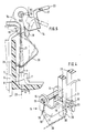
- the application of force from the pressure hood 24 to the angle lever 14 or its second lever arm 17, 18 takes place through a reflector 27 fixedly connected to the pressure hood 24 or with two legs 28 made in one piece with it, which are guided downwards parallel to the longitudinal axis of the housing. These legs 28 are provided with two oblique expansion flanks 29 at the lower end. Above there are two wedge-shaped recesses 30, into which the tabs 23 engage and with which they form an articulated connection.
- the legs 28 push the lever arm 17, 18 of the angle lever 14 down and move the snap spring 20 over the dead position T. After the release, the return spring 22 pivots the angle lever 14 back into the starting position.
- the smallest distance between the wedge flanks of the bearings 30 corresponds to the thickness of the tabs 23.
- the wedge angle of the bearings 30 also corresponds to the desired swivel angle of the angle lever 14.
- the flanks of the bearings 30 thus limit the swivel path of the angle lever 14 as end stops.
- the lower flanks of the bearings 30 can be chamfered if the assembled pressure hood 24 should also be removable.
- the reflector 27 is made in one piece with the legs 28 and acts directly on the angle lever 14, the assembly of the switch is comparatively simple.
- the reflector 27 with the pressure hood 24 firmly attached is introduced into the switch housing 1 from above (see FIGS. 1 and 2).
- the legs 28 slide with the spreading flanks 29 past the tab 23 and spread apart until they engage with the tab 23. After locking, the reflector 27 and the pressure hood 24 are captively connected to the switch.
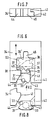
- the journal 32 of a rotary bolt 31 is rotatably mounted in the bearing block 12. This is provided with two cams 33 which, as described later, facilitate the assembly of the switch.
- the axle journal is designed to be comparatively large in terms of diameter and length, so that the locking bolt 31 is mounted in the bearing block 12 with as little play and wear as possible and can cooperate reliably with the link 34.
- the angle lever 14 is pivoted over the dead position T and the switch contact is closed.
- the return spring 22 moves the link 34 back to the latching position, in which the rounded corner 38 of the link engages in the second recess 39 of the rotary latch 31 (position S1 shown in broken lines in FIG. 6).
- the latching position is released by pressing the pressure hood 24 a second time.
- the link 34 moves downward again, hits the rounded flank 40 of the rotary latch 31 with the rounded edge 36 and rotates it further until it lies transversely (dash-dotted position S2 in Fig. 6) and the backdrop 34 stops.
- the return spring 22 then pushes the link 34 upward again.
- the rounded edge 38 continues to turn the rotary latch 31 clockwise until one of its straight sides abuts the surface 41 of the link curve and holds it in this rotational position until the next switching operation.
- the link 34 has a recess 42 at the open end. This facilitates the assembly process in connection with the cams 33. If the pressure hood 24 and reflector 27 are inserted into the switch housing 1 from above (as shown in FIG. 2), the position of the rotary latch 31 is indefinite. If it lies transversely as shown in FIG. 8, the link 34 meets with its corner 43 on one of the cams 33 and rotates the rotary latch 31 in a clockwise direction. During the further displacement, the rounded rotary bolt flank 40 meets the wedge flank 44 of the link curve and continues to rotate until it lies with its straight flank on the surface 41 of the link curve and is held in this rotational position.
- the rotational position of the rotary latch 31 is therefore without influence.
- the rotary latch 31 is automatically brought into the correct starting position.
- the link 34 is further provided with an upwardly facing recess 45 which is diametrically opposite the space between the legs 28. It is used to mount a light source.
- An LED 46 as a light source is attached to a holder 47.
- Your plug contact 48 is guided downward parallel to the longitudinal axis of the switch housing.
- the holder 47 is pushed with two cam-shaped projections between the legs 28 and into the recess 45.
- the recess 45 and the mutually facing side surfaces 54 of the legs 28 form a guide which, when the LED 46 is inserted, moves along the cam-like projections on the holder 47.
- the length of this guide which is at least equal to the switching path S, is limited on the one hand by stop surfaces 55 and on the other hand by cams 56 on the legs 28.
- the cams 56 are each attached to one of the legs 28 and face one another.
- the pressure hood 24 and the reflector 27 firmly connected to it form a tool for inserting the LED 46.
- the pressure hood 24 with the LED 46 inserted in the guide 28, 45, 55, 56 is inserted into the upper end of the housing 1 inserted.
- the plug contacts 48 are inserted into complementary plug sleeves 52, 53 on the housing, which are conductively connected to the rear lamp springs 49.
- the LED 46 assumes the position intended for them and the switch is ready for operation.
- the LED 46 is replaced by the fact that the pressure hood 28 together with the Re flector 27 is pulled out of the housing 1.
- the cams 56 hook one of the two cam-like projections on the holder 47 and pull the LED 46 out of the plug sleeves 52. If the LED 46 is inserted, the essentially cylindrical reflector 27 surrounds it on all sides. This mutual relationship is also maintained when the pressure hood 24 is depressed by the switching path S and held by the rotary latch 31.
- the switch is largely assembled on the base 5 and checked for its function. Then the base 5 is inserted into the cylindrical casing of the housing 1 and firmly connected to it. Then the pressure hood 24 with the reflector 25 and optionally with the LED 46 are used.
Landscapes
- Mechanisms For Operating Contacts (AREA)
- Push-Button Switches (AREA)
Applications Claiming Priority (2)
| Application Number | Priority Date | Filing Date | Title |
|---|---|---|---|
| CH2821/89A CH679092A5 (fr) | 1989-07-28 | 1989-07-28 | |
| CH2821/89 | 1989-07-28 |
Publications (2)
| Publication Number | Publication Date |
|---|---|
| EP0410281A2 true EP0410281A2 (fr) | 1991-01-30 |
| EP0410281A3 EP0410281A3 (en) | 1992-12-09 |
Family
ID=4242346
Family Applications (1)
| Application Number | Title | Priority Date | Filing Date |
|---|---|---|---|
| EP19900113722 Withdrawn EP0410281A3 (en) | 1989-07-28 | 1990-07-18 | Push button switch or key switch |
Country Status (4)
| Country | Link |
|---|---|
| US (1) | US5095184A (fr) |
| EP (1) | EP0410281A3 (fr) |
| JP (1) | JPH0367421A (fr) |
| CH (1) | CH679092A5 (fr) |
Families Citing this family (3)
| Publication number | Priority date | Publication date | Assignee | Title |
|---|---|---|---|---|
| US5560475A (en) * | 1994-12-14 | 1996-10-01 | Brundage; Douglas L. | Illuminated rocker buttons with light dams |
| KR100319214B1 (ko) * | 1999-07-15 | 2002-01-05 | 이철환 | 스위치 |
| FR2859818B1 (fr) * | 2003-09-12 | 2013-07-26 | Itt Mfg Enterprises Inc | Dispositif de commutation equipe d'une source lumineuse |
Family Cites Families (8)
| Publication number | Priority date | Publication date | Assignee | Title |
|---|---|---|---|---|
| DE1248132B (de) * | 1965-12-27 | 1967-08-24 | Walther Bueromasch Gmbh | Elektrischer Schnapptaster |
| JPS56114228A (en) * | 1980-02-13 | 1981-09-08 | Sandengiyoushiya Kk | Illumination type pushhbutton switch |
| CH650618A5 (de) * | 1980-07-08 | 1985-07-31 | Olten Ag Elektro Apparatebau | Drucktaste mit impuls- oder rastfunktion. |
| US4431879A (en) * | 1981-10-06 | 1984-02-14 | Nihon Kaiheiki Kogyo Kabushiki Kaisha | Illumination-type pushbutton switch construction |
| CH653171A5 (de) * | 1981-11-05 | 1985-12-13 | Olten Ag Elektro Apparatebau | Tastschalter. |
| US4447685A (en) * | 1982-02-28 | 1984-05-08 | Nihon Kaiheiki Kogyo Kabushiki Kaisha | Small-sized push-button switch |
| EP0160206A3 (fr) * | 1984-03-22 | 1987-07-22 | Omron Tateisi Electronics Co. | Commutateur à bouton-poussoirs |
| EP0188215B1 (fr) * | 1985-01-08 | 1992-08-05 | Omron Tateisi Electronics Co. | Interrupteur à bouton-poussoir |
-
1989
- 1989-07-28 CH CH2821/89A patent/CH679092A5/de not_active IP Right Cessation
-
1990
- 1990-07-18 EP EP19900113722 patent/EP0410281A3/de not_active Withdrawn
- 1990-07-27 JP JP2201047A patent/JPH0367421A/ja active Pending
- 1990-07-30 US US07/559,663 patent/US5095184A/en not_active Expired - Fee Related
Also Published As
| Publication number | Publication date |
|---|---|
| US5095184A (en) | 1992-03-10 |
| CH679092A5 (fr) | 1991-12-13 |
| JPH0367421A (ja) | 1991-03-22 |
| EP0410281A3 (en) | 1992-12-09 |
Similar Documents
| Publication | Publication Date | Title |
|---|---|---|
| DE102004031110A1 (de) | Sicherungsschalter | |
| DE69513746T2 (de) | Schutzschalter | |
| DE69111749T2 (de) | Steuerseilselbsteinstellvorrichtung. | |
| DE2140161C3 (de) | Schalter, insbesondere Tastschalter | |
| EP0410282A2 (fr) | Commutateur | |
| DE112008001364T5 (de) | Verbinder für Fluiddruckvorrichtungen | |
| DE2740365C3 (de) | Impulsschalter | |
| DE3021598A1 (de) | Drucktastenschalter | |
| EP0410281A2 (fr) | Commutateur à bouton poussoirs ou commutateur à touche | |
| DE60128356T2 (de) | Mechanische rücksetzvorrichtung für schalter | |
| DE69006865T2 (de) | Umgebungskompensator für thermisches Überlastrelais. | |
| DE10155678A1 (de) | Einspannvorrichtung für ein Kraftstoffeinspritzventil | |
| EP0786143A1 (fr) | Micro-interrupteur instantane a profile cuneiforme sur le levier de contact pivotant dans l'interrupteur | |
| DE69606581T2 (de) | Schliessvorrichtung für Steckdosenöffnungen | |
| EP0119952B1 (fr) | Dispositif de verrouillage pour un connecteur enfichable | |
| DE3905079C2 (fr) | ||
| DE2827854C2 (de) | Elektrischer Wippenschalter | |
| DE3839911C1 (en) | Electrical switch | |
| EP4402709B1 (fr) | Élément de commutation à rupture brusque doté d'un contact à ouverture ou à fermeture | |
| DE3112295A1 (de) | Sicherungssockel fuer schmelzsicherungseinsaetze | |
| DE19955640B4 (de) | Elektrische Schaltvorrichtung | |
| DE3146271A1 (de) | Kraftfahrzeug-lenkstockschalter mit rueckstellung | |
| DE1055649B (de) | Temperaturabhaengiger elektrischer Schalter mit Rueckstelleinrichtung | |
| DE7320723U (de) | Fahrtrichtungs Fernlicht Abblendlicht Lichthupen Schalter | |
| DE19741926C1 (de) | Schalter |
Legal Events
| Date | Code | Title | Description |
|---|---|---|---|
| PUAI | Public reference made under article 153(3) epc to a published international application that has entered the european phase |
Free format text: ORIGINAL CODE: 0009012 |
|
| AK | Designated contracting states |
Kind code of ref document: A2 Designated state(s): AT BE DE DK ES FR GB GR IT LU NL SE |
|
| PUAL | Search report despatched |
Free format text: ORIGINAL CODE: 0009013 |
|
| AK | Designated contracting states |
Kind code of ref document: A3 Designated state(s): AT BE DE DK ES FR GB GR IT LU NL SE |
|
| STAA | Information on the status of an ep patent application or granted ep patent |
Free format text: STATUS: THE APPLICATION IS DEEMED TO BE WITHDRAWN |
|
| 18D | Application deemed to be withdrawn |
Effective date: 19930610 |