EP0410527A1 - Fouet pour un robot de cuisine - Google Patents
Fouet pour un robot de cuisine Download PDFInfo
- Publication number
- EP0410527A1 EP0410527A1 EP90201997A EP90201997A EP0410527A1 EP 0410527 A1 EP0410527 A1 EP 0410527A1 EP 90201997 A EP90201997 A EP 90201997A EP 90201997 A EP90201997 A EP 90201997A EP 0410527 A1 EP0410527 A1 EP 0410527A1
- Authority
- EP
- European Patent Office
- Prior art keywords
- shaft
- brackets
- axial direction
- ring
- whisk
- Prior art date
- Legal status (The legal status is an assumption and is not a legal conclusion. Google has not performed a legal analysis and makes no representation as to the accuracy of the status listed.)
- Granted
Links
- 235000013305 food Nutrition 0.000 title claims abstract description 4
- 238000010276 construction Methods 0.000 abstract 1
- 239000000463 material Substances 0.000 description 11
- 238000000034 method Methods 0.000 description 5
- 230000008569 process Effects 0.000 description 5
- 230000000694 effects Effects 0.000 description 4
- 239000008267 milk Substances 0.000 description 4
- 210000004080 milk Anatomy 0.000 description 4
- 235000013336 milk Nutrition 0.000 description 4
- 230000003245 working effect Effects 0.000 description 3
- 230000009471 action Effects 0.000 description 2
- 235000015243 ice cream Nutrition 0.000 description 2
- 238000004898 kneading Methods 0.000 description 2
- 238000004519 manufacturing process Methods 0.000 description 2
- 239000000203 mixture Substances 0.000 description 2
- 238000003756 stirring Methods 0.000 description 2
- 238000010009 beating Methods 0.000 description 1
- 230000008901 benefit Effects 0.000 description 1
- 235000013361 beverage Nutrition 0.000 description 1
- 230000015572 biosynthetic process Effects 0.000 description 1
- 230000008878 coupling Effects 0.000 description 1
- 238000010168 coupling process Methods 0.000 description 1
- 238000005859 coupling reaction Methods 0.000 description 1
- 238000012986 modification Methods 0.000 description 1
- 230000004048 modification Effects 0.000 description 1
- 238000005507 spraying Methods 0.000 description 1
Images

Classifications
-
- A—HUMAN NECESSITIES
- A47—FURNITURE; DOMESTIC ARTICLES OR APPLIANCES; COFFEE MILLS; SPICE MILLS; SUCTION CLEANERS IN GENERAL
- A47J—KITCHEN EQUIPMENT; COFFEE MILLS; SPICE MILLS; APPARATUS FOR MAKING BEVERAGES
- A47J43/00—Implements for preparing or holding food, not provided for in other groups of this subclass
- A47J43/04—Machines for domestic use not covered elsewhere, e.g. for grinding, mixing, stirring, kneading, emulsifying, whipping or beating foodstuffs, e.g. power-driven
- A47J43/07—Parts or details, e.g. mixing tools, whipping tools
-
- A—HUMAN NECESSITIES
- A47—FURNITURE; DOMESTIC ARTICLES OR APPLIANCES; COFFEE MILLS; SPICE MILLS; SUCTION CLEANERS IN GENERAL
- A47J—KITCHEN EQUIPMENT; COFFEE MILLS; SPICE MILLS; APPARATUS FOR MAKING BEVERAGES
- A47J43/00—Implements for preparing or holding food, not provided for in other groups of this subclass
- A47J43/04—Machines for domestic use not covered elsewhere, e.g. for grinding, mixing, stirring, kneading, emulsifying, whipping or beating foodstuffs, e.g. power-driven
- A47J43/07—Parts or details, e.g. mixing tools, whipping tools
- A47J43/0705—Parts or details, e.g. mixing tools, whipping tools for machines with tools driven from the upper side
- A47J43/0711—Parts or details, e.g. mixing tools, whipping tools for machines with tools driven from the upper side mixing, whipping or cutting tools
-
- B—PERFORMING OPERATIONS; TRANSPORTING
- B01—PHYSICAL OR CHEMICAL PROCESSES OR APPARATUS IN GENERAL
- B01F—MIXING, e.g. DISSOLVING, EMULSIFYING OR DISPERSING
- B01F27/00—Mixers with rotary stirring devices in fixed receptacles; Kneaders
- B01F27/05—Stirrers
- B01F27/07—Stirrers characterised by their mounting on the shaft
- B01F27/072—Stirrers characterised by their mounting on the shaft characterised by the disposition of the stirrers with respect to the rotating axis
- B01F27/0725—Stirrers characterised by their mounting on the shaft characterised by the disposition of the stirrers with respect to the rotating axis on the free end of the rotating axis
Definitions
- the invention relates to a whisk for a kitchen machine, which has a shaft from which at least four arc-shaped brackets project in the radial direction, evenly offset at an angle, which are connected to one another at their projecting ends.
- GB-OS 2 188 495 shows such whorls which have four arch-shaped brackets which project from one end of a shaft and, viewed in an axial direction of the shaft, describe an arc of 180 °, their ends projecting from the shaft being connected directly to one another , so that the whorl as a whole forms an integral part. Since these whorls only have four stirrups, their impact and mixing action is relatively limited.
- the invention has set itself the goal of designing a whisk of the type mentioned at the outset in such a way that on the one hand it gives a good impact and mixing action and on the other hand it is simple to produce as a one-piece part.
- the provision of the ring, into which the bow ends with their ends projecting from the shaft and which thus connects these ends to one another achieves a very good strength or stability of the bow-shaped bow, as a result of which the whorl can also be used to process goods with a firmer consistency, such as ice cream to be mixed into the material to be processed is very suitable. Seen overall, a whisk is obtained which has very good working properties and which can be easily manufactured as a one-piece part.
- a kneading or stirring device in which, as a special tool, a plug-on part is provided on a kneading or stirring tool, which has a ring, from which the spoke-like semicircular bracket starts all are oriented in an arc shape in one direction, so that the plug-on part as a whole is shell-like. It has been shown that with such a one-sided arc-shaped orientation of the stirrups, only a limited impact and mixing effect can be achieved, because the stirrups mainly set the material to be processed in one direction.
- a whisk according to the invention which is designed as a one-piece part, the brackets arranged and designed so that they alternately run on the one hand in an axial direction of the shaft and on the other hand in the opposite axial direction of the shaft, whereby a very good impact and Mixing effect is achieved.
- brackets can be oriented in pairs in the same arc, so that two consecutive brackets seen in the circumferential direction of the ring in an axial direction of the shaft and the subsequent two brackets in the opposite axial direction of the shaft extend arcuately.
- two brackets can, for example, run in an arc shape in one axial direction of the shaft and the subsequent bracket in the opposite axial direction of the shaft, wherein a total of nine, twelve or fifteen brackets can be provided, for example.
- the material to be processed is set in motion in succession in different directions by the brackets, as a result of which good mixing properties of the whisk are obtained, the whisk itself also having a high strength or stability, since the ends of the bracket projecting from the shaft immediately open into the ring in succession from opposite sides.
- the stirrups can be elliptical or polygonal, whereby they can form arches of 90 ° or 180 °.
- the arc-shaped brackets are semicircular. It has been shown that very good working properties of the whorl are obtained with such a configuration of the stirrups, wherein in particular splashing of the material to be processed is largely avoided.
- the working properties of the whisk can be significantly influenced thereby. If only a small number of stirrups are provided, for example in the case of the known whisk mentioned at the beginning, it takes a relatively long time for the material to be processed to be thoroughly mixed. If the number of stirrups chosen is too large, this also results in a relatively long processing time, since the stirrups process the material in rapid succession, so that there is not enough time to be able to follow the mixing process. In this context, it has proven to be particularly advantageous if the number of arched brackets is chosen to be twelve. With such a number of bow-shaped stirrups, particularly good whipping and mixing properties of the whisk are obtained and thus a short processing time is achieved.
- Fig. 1 shows in section a whorl, in which the arcuate brackets projecting from its shaft open at their free ends into a ring connecting these ends, with a bracket viewed in a circumferential direction of the ring immediately following one another in an axial direction of the shaft and the subsequent bracket is arcuate in the opposite axial direction of the shaft and the bracket itself is semicircular.
- 2 shows the whorl according to FIG. 1 in plan view from the shaft.
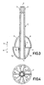
- Fig.3 shows in section a whorl, in which the arcuate temples are elliptical, describing an arc of 900. 4 shows the whorl according to FIG. 3 in plan view from the shaft.
- the whisk shown in Figures 1 and 2 has a shaft 1, which is provided at one end 2 with a plurality of ribs 3, which are used in the usual way for positive coupling with a drive part of a food processor to set the whisk in rotation.
- a number of curved brackets 5 and 6 protrude in the radial direction, evenly offset at an angle, which form the striking and mixing tools of the whisk.
- a total of twelve arc-shaped brackets 5 and 6 are provided which, with their ends protruding from the shaft 1, open into a ring 7 which extends concentrically to the shaft 1 and at a radial distance from the same and which thus connects the projecting ends of all the brackets to one another .
- the brackets 5 and 6 are formed in the present case semi-circular, so that they describe an arc of 1800. Furthermore, the brackets are arranged so that, seen from them in a circumferential direction of the ring 7, evenly distributed, alternately a number of six brackets 5 in an axial direction of the shaft 1, which is indicated by the arrow 8, and a further number of six brackets 6 in the opposite axial direction of the shaft 1, which is indicated by the arrow 9, arcuate.
- the arrangement of the stirrups is additionally such that, seen in a circumferential direction of the ring 7, one stirrup 5 in the axial direction of the shaft 1 indicated by the arrow 8 and the following stirrup 6 in the direction indicated by the arrow 9 follow one after the other specified opposite axial direction of the shaft 1 runs arcuately.
- the number of stirrups provided has also proven to be important, which in the present exemplary embodiment is chosen to be twelve, as a result of which particularly good impact and mixing properties of the whisk are obtained and thus a short processing time is obtained. If only a small number of stirrups is provided, for example four stirrups, it takes a relatively long time for the material to be processed to be thoroughly mixed. If the number of stirrups chosen is too large, this also results in a relatively long processing time, since the stirrups process the material in rapid succession, so that there is not enough time to be able to follow the mixing process. The provision of twelve stirrups has proven to be advantageous in this context.
- Another significant advantage of the whorl described above is that it can be manufactured particularly easily as a one-piece part. This is due to the fact that the individual brackets 5 and 6 do not form an arc extending through 180 ° in the axial direction of the shaft 1, but with respect to the ring 7 alternately in one of the two axial directions of the shaft 1 indicated by the arrows 8 and 9 are oriented in an arc of 180 °. In this way, a simple two-part tool for producing the one-piece whorls are used, which is divided in the plane of the ring 7 and can be opened in the axial direction of the shaft 1. Such a whisk is therefore very inexpensive to manufacture.
- the whorl has a total of ten arc-shaped brackets 10 and 11, which are elliptical here and describe an arc of 90 °.
- the brackets 10 protrude directly from the end 4 of the shaft 1, whereas the brackets 11 protrude from a section thereof which is more towards the center of the shaft 1.
- the ends of all brackets 10 and 11 projecting from the shaft 1 open again into a ring 7 which connects these ends to one another.
Landscapes
- Engineering & Computer Science (AREA)
- Mechanical Engineering (AREA)
- Food Science & Technology (AREA)
- Chemical & Material Sciences (AREA)
- Chemical Kinetics & Catalysis (AREA)
- Food-Manufacturing Devices (AREA)
- Mixers Of The Rotary Stirring Type (AREA)
- Cereal-Derived Products (AREA)
- General Preparation And Processing Of Foods (AREA)
- Grinding-Machine Dressing And Accessory Apparatuses (AREA)
- Disintegrating Or Milling (AREA)
- Manufacturing And Processing Devices For Dough (AREA)
- Distillation Of Fermentation Liquor, Processing Of Alcohols, Vinegar And Beer (AREA)
- Adjustment And Processing Of Grains (AREA)
- Crushing And Pulverization Processes (AREA)
- Meat, Egg Or Seafood Products (AREA)
- Apparatuses For Bulk Treatment Of Fruits And Vegetables And Apparatuses For Preparing Feeds (AREA)
Applications Claiming Priority (2)
| Application Number | Priority Date | Filing Date | Title |
|---|---|---|---|
| AT1816/89 | 1989-07-27 | ||
| AT1816/89A AT392581B (de) | 1989-07-27 | 1989-07-27 | Quirl fuer eine kuechenmaschine |
Publications (2)
| Publication Number | Publication Date |
|---|---|
| EP0410527A1 true EP0410527A1 (fr) | 1991-01-30 |
| EP0410527B1 EP0410527B1 (fr) | 1993-06-16 |
Family
ID=3521610
Family Applications (1)
| Application Number | Title | Priority Date | Filing Date |
|---|---|---|---|
| EP90201997A Expired - Lifetime EP0410527B1 (fr) | 1989-07-27 | 1990-07-23 | Fouet pour un robot de cuisine |
Country Status (6)
| Country | Link |
|---|---|
| EP (1) | EP0410527B1 (fr) |
| JP (1) | JP2540874Y2 (fr) |
| KR (1) | KR970000756Y1 (fr) |
| AT (2) | AT392581B (fr) |
| DE (1) | DE59001765D1 (fr) |
| ES (1) | ES2043255T3 (fr) |
Cited By (2)
| Publication number | Priority date | Publication date | Assignee | Title |
|---|---|---|---|---|
| EP0678269A1 (fr) * | 1994-04-23 | 1995-10-25 | Braun Aktiengesellschaft | Batteur-mélangeur |
| EP0799593A1 (fr) | 1996-04-06 | 1997-10-08 | Braun Aktiengesellschaft | Outil de mixage pour un appareil de cuisine pour mélanger et mousser de la nourriture |
Families Citing this family (3)
| Publication number | Priority date | Publication date | Assignee | Title |
|---|---|---|---|---|
| DE102009045706A1 (de) | 2009-10-14 | 2011-04-21 | BSH Bosch und Siemens Hausgeräte GmbH | Rührvorrichtung für ein elektrisches Küchengerät |
| DE102009057448A1 (de) | 2009-12-09 | 2011-06-16 | BSH Bosch und Siemens Hausgeräte GmbH | Küchengerät mit Rührvorrichtung |
| EP2545829A1 (fr) * | 2011-07-12 | 2013-01-16 | Koninklijke Philips Electronics N.V. | Un élément de protection pour un joint d'étanchéité dans un dispositif mélangeur pour faire mousser du lait |
Citations (4)
| Publication number | Priority date | Publication date | Assignee | Title |
|---|---|---|---|---|
| US2749098A (en) * | 1955-07-21 | 1956-06-05 | Albert H Johnson | Mixer |
| CH471190A (de) * | 1966-03-22 | 1969-04-15 | Stamicarbon | Verfahren zur Aufarbeitung einer Suspension |
| DE1579447A1 (de) * | 1965-04-17 | 1970-08-27 | Paul Kg Alfred | Knet- oder Ruehrvorrichtung fuer Kuechenmaschinen |
| GB2188495A (en) * | 1986-03-26 | 1987-09-30 | Thorn Emi Appliances | A battery-operated, rechargeable domestic appliance and a unit for supporting and charging the same |
Family Cites Families (3)
| Publication number | Priority date | Publication date | Assignee | Title |
|---|---|---|---|---|
| JPS5847212A (ja) * | 1981-09-17 | 1983-03-18 | Fanuc Ltd | ロ−タリエンコ−ダ |
| JPS59133149U (ja) * | 1983-02-25 | 1984-09-06 | 西山 典秀 | 泡立器 |
| JPS6030486A (ja) * | 1983-07-30 | 1985-02-16 | Noriaki Wakao | 無動力ポンプ |
-
1989
- 1989-07-27 AT AT1816/89A patent/AT392581B/de active
-
1990
- 1990-07-23 AT AT90201997T patent/ATE90535T1/de not_active IP Right Cessation
- 1990-07-23 EP EP90201997A patent/EP0410527B1/fr not_active Expired - Lifetime
- 1990-07-23 DE DE9090201997T patent/DE59001765D1/de not_active Expired - Fee Related
- 1990-07-23 ES ES90201997T patent/ES2043255T3/es not_active Expired - Lifetime
- 1990-07-24 JP JP1990077908U patent/JP2540874Y2/ja not_active Expired - Lifetime
- 1990-07-27 KR KR2019900011111U patent/KR970000756Y1/ko not_active Expired - Fee Related
Patent Citations (4)
| Publication number | Priority date | Publication date | Assignee | Title |
|---|---|---|---|---|
| US2749098A (en) * | 1955-07-21 | 1956-06-05 | Albert H Johnson | Mixer |
| DE1579447A1 (de) * | 1965-04-17 | 1970-08-27 | Paul Kg Alfred | Knet- oder Ruehrvorrichtung fuer Kuechenmaschinen |
| CH471190A (de) * | 1966-03-22 | 1969-04-15 | Stamicarbon | Verfahren zur Aufarbeitung einer Suspension |
| GB2188495A (en) * | 1986-03-26 | 1987-09-30 | Thorn Emi Appliances | A battery-operated, rechargeable domestic appliance and a unit for supporting and charging the same |
Cited By (3)
| Publication number | Priority date | Publication date | Assignee | Title |
|---|---|---|---|---|
| EP0678269A1 (fr) * | 1994-04-23 | 1995-10-25 | Braun Aktiengesellschaft | Batteur-mélangeur |
| US5590962A (en) * | 1994-04-23 | 1997-01-07 | Braun Aktiengesellschaft | Rotating beater |
| EP0799593A1 (fr) | 1996-04-06 | 1997-10-08 | Braun Aktiengesellschaft | Outil de mixage pour un appareil de cuisine pour mélanger et mousser de la nourriture |
Also Published As
| Publication number | Publication date |
|---|---|
| KR970000756Y1 (ko) | 1997-02-06 |
| AT392581B (de) | 1991-04-25 |
| ATA181689A (de) | 1990-10-15 |
| JPH0330947U (fr) | 1991-03-26 |
| DE59001765D1 (de) | 1993-07-22 |
| KR910002322U (ko) | 1991-02-25 |
| ES2043255T3 (es) | 1993-12-16 |
| ATE90535T1 (de) | 1993-07-15 |
| EP0410527B1 (fr) | 1993-06-16 |
| JP2540874Y2 (ja) | 1997-07-09 |
Similar Documents
| Publication | Publication Date | Title |
|---|---|---|
| DE2801549C2 (de) | Vorrichtung zum Mischen von Zutaten zur Herstellung von Soßen | |
| DE29705741U1 (de) | Dynamischer Mischer für zahnärztliche Abdruckmassen | |
| DE2232436A1 (de) | Mischvorrichtung | |
| DE60307493T2 (de) | Knetmaschine für Teigmittel, insbesondere für Backwaren | |
| EP0410527B1 (fr) | Fouet pour un robot de cuisine | |
| EP0009666B1 (fr) | Outil mélangeur et pétrisseur notamment pour machines à pétrir la pâte à haut régime | |
| EP0678269B1 (fr) | Batteur-mélangeur | |
| DD213826A5 (de) | Vorrichtung zur bildung einer kugel aus plastischem material | |
| EP0239829A2 (fr) | Outil mélangeur-pétrisseur | |
| DE69602057T2 (de) | Haushalts-Mischeinrichtung | |
| EP0137136B1 (fr) | Instrument pour machine domestique, spécialement pour ustensiles de cuisine | |
| EP0799593A1 (fr) | Outil de mixage pour un appareil de cuisine pour mélanger et mousser de la nourriture | |
| DE4220234C2 (de) | Küchenmaschine | |
| DE69908471T2 (de) | Kontinuierlich arbeitende Knetmaschine | |
| EP2509480B1 (fr) | Appareil de cuisine avec dispositif mélangeur | |
| EP0109580B1 (fr) | Dispositif pour mélanger des ingrédients pour la préparation de sauces | |
| DE3144438A1 (de) | Kuechenmaschine mit motorischem antrieb | |
| DE1201273B (de) | Knet- und Mischwerkzeug, besonders fuer Teigknetmischer | |
| DE60109143T2 (de) | Vorrichtung mit variabler Neigung zur Verfeinerung von Nahrungsmitteln | |
| DD290615A5 (de) | Vorrichtung zum zerteilen einer vielzahl kleiner keramischer massestraenge in kurze strangabschnitte | |
| DE732644C (de) | Kegelbrecher | |
| DE86239C (fr) | ||
| DE193399C (fr) | ||
| DE2142163A1 (de) | Silageschneidvorrichtung | |
| DE2202542A1 (de) | Vorrichtung zum Mischen,Kneten oder Trocknen von Stoffen |
Legal Events
| Date | Code | Title | Description |
|---|---|---|---|
| PUAI | Public reference made under article 153(3) epc to a published international application that has entered the european phase |
Free format text: ORIGINAL CODE: 0009012 |
|
| AK | Designated contracting states |
Kind code of ref document: A1 Designated state(s): AT DE ES FR GB IT |
|
| 17P | Request for examination filed |
Effective date: 19910725 |
|
| 17Q | First examination report despatched |
Effective date: 19920819 |
|
| GRAA | (expected) grant |
Free format text: ORIGINAL CODE: 0009210 |
|
| AK | Designated contracting states |
Kind code of ref document: B1 Designated state(s): AT DE ES FR GB IT |
|
| REF | Corresponds to: |
Ref document number: 90535 Country of ref document: AT Date of ref document: 19930715 Kind code of ref document: T |
|
| REF | Corresponds to: |
Ref document number: 59001765 Country of ref document: DE Date of ref document: 19930722 |
|
| ITF | It: translation for a ep patent filed | ||
| ET | Fr: translation filed | ||
| GBT | Gb: translation of ep patent filed (gb section 77(6)(a)/1977) |
Effective date: 19930913 |
|
| PLBE | No opposition filed within time limit |
Free format text: ORIGINAL CODE: 0009261 |
|
| STAA | Information on the status of an ep patent application or granted ep patent |
Free format text: STATUS: NO OPPOSITION FILED WITHIN TIME LIMIT |
|
| 26N | No opposition filed | ||
| ITPR | It: changes in ownership of a european patent |
Owner name: CAMBIO RAGIONE SOCIALE;PHILIPS ELECTRONICS N.V. |
|
| REG | Reference to a national code |
Ref country code: FR Ref legal event code: CD |
|
| REG | Reference to a national code |
Ref country code: ES Ref legal event code: PC2A Owner name: PHILIPS ELECTRONICS N.V. |
|
| PGFP | Annual fee paid to national office [announced via postgrant information from national office to epo] |
Ref country code: ES Payment date: 19980708 Year of fee payment: 9 |
|
| PGFP | Annual fee paid to national office [announced via postgrant information from national office to epo] |
Ref country code: AT Payment date: 19980728 Year of fee payment: 9 |
|
| REG | Reference to a national code |
Ref country code: FR Ref legal event code: CD |
|
| REG | Reference to a national code |
Ref country code: ES Ref legal event code: PC2A |
|
| PG25 | Lapsed in a contracting state [announced via postgrant information from national office to epo] |
Ref country code: AT Free format text: LAPSE BECAUSE OF NON-PAYMENT OF DUE FEES Effective date: 19990723 |
|
| PG25 | Lapsed in a contracting state [announced via postgrant information from national office to epo] |
Ref country code: ES Free format text: LAPSE BECAUSE OF NON-PAYMENT OF DUE FEES Effective date: 19990724 |
|
| PGFP | Annual fee paid to national office [announced via postgrant information from national office to epo] |
Ref country code: FR Payment date: 20010725 Year of fee payment: 12 |
|
| PGFP | Annual fee paid to national office [announced via postgrant information from national office to epo] |
Ref country code: GB Payment date: 20010731 Year of fee payment: 12 |
|
| PGFP | Annual fee paid to national office [announced via postgrant information from national office to epo] |
Ref country code: DE Payment date: 20010919 Year of fee payment: 12 |
|
| REG | Reference to a national code |
Ref country code: GB Ref legal event code: IF02 |
|
| PG25 | Lapsed in a contracting state [announced via postgrant information from national office to epo] |
Ref country code: GB Free format text: LAPSE BECAUSE OF NON-PAYMENT OF DUE FEES Effective date: 20020723 |
|
| PG25 | Lapsed in a contracting state [announced via postgrant information from national office to epo] |
Ref country code: DE Free format text: LAPSE BECAUSE OF NON-PAYMENT OF DUE FEES Effective date: 20030201 |
|
| GBPC | Gb: european patent ceased through non-payment of renewal fee |
Effective date: 20020723 |
|
| PG25 | Lapsed in a contracting state [announced via postgrant information from national office to epo] |
Ref country code: FR Free format text: LAPSE BECAUSE OF NON-PAYMENT OF DUE FEES Effective date: 20030331 |
|
| REG | Reference to a national code |
Ref country code: FR Ref legal event code: ST |
|
| REG | Reference to a national code |
Ref country code: ES Ref legal event code: FD2A Effective date: 20000810 |
|
| PG25 | Lapsed in a contracting state [announced via postgrant information from national office to epo] |
Ref country code: IT Free format text: LAPSE BECAUSE OF NON-PAYMENT OF DUE FEES;WARNING: LAPSES OF ITALIAN PATENTS WITH EFFECTIVE DATE BEFORE 2007 MAY HAVE OCCURRED AT ANY TIME BEFORE 2007. THE CORRECT EFFECTIVE DATE MAY BE DIFFERENT FROM THE ONE RECORDED. Effective date: 20050723 |