EP0410779A2 - Structure d'une pÀ©dale amortissant les vibrations d'un véhicule - Google Patents
Structure d'une pÀ©dale amortissant les vibrations d'un véhicule Download PDFInfo
- Publication number
- EP0410779A2 EP0410779A2 EP90308248A EP90308248A EP0410779A2 EP 0410779 A2 EP0410779 A2 EP 0410779A2 EP 90308248 A EP90308248 A EP 90308248A EP 90308248 A EP90308248 A EP 90308248A EP 0410779 A2 EP0410779 A2 EP 0410779A2
- Authority
- EP
- European Patent Office
- Prior art keywords
- pedal
- mass
- housing
- pad
- section
- Prior art date
- Legal status (The legal status is an assumption and is not a legal conclusion. Google has not performed a legal analysis and makes no representation as to the accuracy of the status listed.)
- Ceased
Links
- 230000000717 retained effect Effects 0.000 claims abstract description 6
- 238000003780 insertion Methods 0.000 claims description 4
- 230000037431 insertion Effects 0.000 claims description 4
- 230000002787 reinforcement Effects 0.000 claims description 4
- 239000013013 elastic material Substances 0.000 claims description 2
- 230000001133 acceleration Effects 0.000 abstract description 3
- 230000005540 biological transmission Effects 0.000 description 3
- XEEYBQQBJWHFJM-UHFFFAOYSA-N Iron Chemical compound [Fe] XEEYBQQBJWHFJM-UHFFFAOYSA-N 0.000 description 2
- 230000001419 dependent effect Effects 0.000 description 2
- 238000004519 manufacturing process Methods 0.000 description 2
- 239000002184 metal Substances 0.000 description 2
- 229910052751 metal Inorganic materials 0.000 description 2
- 239000000853 adhesive Substances 0.000 description 1
- 230000001070 adhesive effect Effects 0.000 description 1
- 238000010276 construction Methods 0.000 description 1
- 230000000881 depressing effect Effects 0.000 description 1
- 229910052742 iron Inorganic materials 0.000 description 1
- 238000012986 modification Methods 0.000 description 1
- 230000004048 modification Effects 0.000 description 1
- 229920002994 synthetic fiber Polymers 0.000 description 1
- 238000003466 welding Methods 0.000 description 1
Images

Classifications
-
- G—PHYSICS
- G05—CONTROLLING; REGULATING
- G05G—CONTROL DEVICES OR SYSTEMS INSOFAR AS CHARACTERISED BY MECHANICAL FEATURES ONLY
- G05G1/00—Controlling members, e.g. knobs or handles; Assemblies or arrangements thereof; Indicating position of controlling members
- G05G1/30—Controlling members actuated by foot
- G05G1/44—Controlling members actuated by foot pivoting
-
- G—PHYSICS
- G05—CONTROLLING; REGULATING
- G05G—CONTROL DEVICES OR SYSTEMS INSOFAR AS CHARACTERISED BY MECHANICAL FEATURES ONLY
- G05G25/00—Other details or appurtenances of control mechanisms, e.g. supporting intermediate members elastically
- G05G25/02—Inhibiting the generation or transmission of noise
-
- Y—GENERAL TAGGING OF NEW TECHNOLOGICAL DEVELOPMENTS; GENERAL TAGGING OF CROSS-SECTIONAL TECHNOLOGIES SPANNING OVER SEVERAL SECTIONS OF THE IPC; TECHNICAL SUBJECTS COVERED BY FORMER USPC CROSS-REFERENCE ART COLLECTIONS [XRACs] AND DIGESTS
- Y10—TECHNICAL SUBJECTS COVERED BY FORMER USPC
- Y10T—TECHNICAL SUBJECTS COVERED BY FORMER US CLASSIFICATION
- Y10T74/00—Machine element or mechanism
- Y10T74/20—Control lever and linkage systems
- Y10T74/20576—Elements
- Y10T74/20888—Pedals
- Y10T74/20912—Pads and covers
-
- Y—GENERAL TAGGING OF NEW TECHNOLOGICAL DEVELOPMENTS; GENERAL TAGGING OF CROSS-SECTIONAL TECHNOLOGIES SPANNING OVER SEVERAL SECTIONS OF THE IPC; TECHNICAL SUBJECTS COVERED BY FORMER USPC CROSS-REFERENCE ART COLLECTIONS [XRACs] AND DIGESTS
- Y10—TECHNICAL SUBJECTS COVERED BY FORMER USPC
- Y10T—TECHNICAL SUBJECTS COVERED BY FORMER US CLASSIFICATION
- Y10T74/00—Machine element or mechanism
- Y10T74/21—Elements
- Y10T74/2164—Cranks and pedals
- Y10T74/2168—Pedals
Definitions
- the present invention relates generally to a structure of a pedal such as an accelerator, clutch, or brake pedal for a vehicle. More particularly, the invention relates to a vibration proofing pedal structure for a vehicle to which a mass having a preselected weight is attached to absorb vibration transmitted from an engine and/or a transmission so as to preventing them from being transmitted to a driver.
- an accelerator pedal for a vehicle serves to adjust an opening of a throttle valve by depressing a pedal pad to control engine speed.
- the pedal pad is attached to a lower end portion of a pedal arm which is pivotably supported by a vehicle body through a bracket and an upper end portion of which is connected to an operation rod extending to an engine.
- a clutch pedal has the same construction as that of the acceleration pedal and is adapted for engaging or disengaging between a transmission and the engine.
- a pedal arm In order to absorb this pedal vibration, a pedal arm is generally well known in the art on which a mass is welded to prevent the arm from vibrating. In this structure, an additional manufacturing step is necessary for welding the mass to the pedal arm. Additionally, due to variations in manufactured pedal arms, the resonance frequencies thereof are different from each other as are the differences in the resonating frequencies of various engines dependent on the type of vehicle.
- the retaining means is a housing integrally formed on the pedal pad.
- the mass includes first and second sections, the first section being fitted into the housing to be retained to the pedal pad, the second section being exposed from the housing.
- a hook means may be provided for engaging with an edge of the second section of the mass to securely retain the mass to the pedal.
- the hook means may be located between the housing and the pedal arm so as to prevent the mass from contacting with the pedal arm whereby noise induced by the contact of the mass with the pedal arm is prevented from occurring.
- the hook means may be made of an elastic material to provide flexibility so as to allow it to swing about a portion connected to the pedal pad for facilitating insertion of the mass into the housing during assembly.
- a vibration proofing structure of a pedal for a vehicle which comprises a pedal pad, a retaining means for detachably retaining the pedal pad to a pedal arm, a housing, integrally formed on the pedal pad, located adjacent the pedal arm retained on the pedal pad by the retaining means, and a mass inserted into the housing, the mass provided with first and second sections, the first section having first geometry corresponding to a dimension of inside of the housing to be fitted into the housing so as to be held to the pedal pad, the second section being exposed from the housing, having second geometry and providing additional weight to the first section so as to vary a resonance frequency of the pedal arm to prevent vibration transmitted to the pedal arm from being transmitted to the pedal pad.
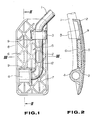
- FIG. 1 a structure of an accelerator pedal for a vehicle according to the present invention is shown.
- This structure includes generally a pedal arm 1, a pedal pad 2 made of a synthetic material, and a mass 5.
- the pedal pad 2 has a fastener 3 and a pedal arm inserted hole 4 which are integrally formed on the back surface of the pedal pad 2 for detachably attaching the pad to an L-shaped end portion of the pedal arm 1.
- the masses 5 is detachably inserted into a pocket portion 6 integrally formed on the back surface of the pedal pad 2.
- the pocket portion 6 extends from a rib reinforcement 8 which is formed around an edge of the back surface of the pedal pad toward the pedal arm 1 to form a rectangular housing C-shaped in cross-section including side walls 9 to open to the pedal arm 1.
- the mass 5 is made of a rectangular iron block which has a preselected width allowing it to be fitted into the pocket portion 6. Therefore, mounting the mass 5 to the pedal pad 2 is accomplished by inserting it into the pocket portion 6 from the opening thereof after which the pedal arm 1 is engaged with the hole 4 and is then retained in place by the fastener 3. It will be appreciated that with the above attaching sequence, the mass 5 is easily attached to the pedal pad 3 with firm engagement with the side walls 9, rib reinforcements 7, and the pedal arm 1 as shown in Fig. 3.
- an adhesive may be used for attaching the mass.
- a center wall 11, as shown in Fig. 4 may be provided between the mass 5 and the pedal arm 1 on the pedal pad 2 which is relatively thin to provide flexibility so as to allow it to swing somewhat about a portion connected to the pedal pad for facilitating insertion of the mass into the pocket portion 6 during assembly.
- the center wall 11 has a hook or stopper 10 for engaging an edge of the mass to hold it securely, thereby preventing it from falling due to variation in temperature or secular distortion and preventing metal contact between the mass and the pedal arm from occurring to reduce noise induced by the metal contact.
- an exposed area 12 thereof may be changed in wall thickness to adjust the entire weight thereof so as to vary a resonance frequency of the pedal arm 1. It will be appreciated that masses having different weights can be attached to the pedal pad 2 easily to adjust the resonance frequency of the pedal arm 1, preventing vibration of the engine or a transmission from being transmitted to a driver.
Landscapes
- Physics & Mathematics (AREA)
- General Physics & Mathematics (AREA)
- Engineering & Computer Science (AREA)
- Automation & Control Theory (AREA)
- Mechanical Control Devices (AREA)
- Auxiliary Drives, Propulsion Controls, And Safety Devices (AREA)
- Vibration Prevention Devices (AREA)
Applications Claiming Priority (2)
| Application Number | Priority Date | Filing Date | Title |
|---|---|---|---|
| JP1989088477U JPH0720743Y2 (ja) | 1989-07-27 | 1989-07-27 | ペダルの防振構造 |
| JP88477/89U | 1989-07-27 |
Publications (2)
| Publication Number | Publication Date |
|---|---|
| EP0410779A2 true EP0410779A2 (fr) | 1991-01-30 |
| EP0410779A3 EP0410779A3 (en) | 1991-12-11 |
Family
ID=13943865
Family Applications (1)
| Application Number | Title | Priority Date | Filing Date |
|---|---|---|---|
| EP19900308248 Ceased EP0410779A3 (en) | 1989-07-27 | 1990-07-27 | Vibration proofing structure of pedal for vehicle |
Country Status (4)
| Country | Link |
|---|---|
| US (1) | US5186076A (fr) |
| EP (1) | EP0410779A3 (fr) |
| JP (1) | JPH0720743Y2 (fr) |
| AU (1) | AU615148B2 (fr) |
Cited By (2)
| Publication number | Priority date | Publication date | Assignee | Title |
|---|---|---|---|---|
| EP0899646A1 (fr) * | 1997-08-27 | 1999-03-03 | Mannesmann VDO Aktiengesellschaft | Pedale pour une voiture |
| CN102039820A (zh) * | 2009-10-22 | 2011-05-04 | 丰田铁工株式会社 | 车辆操作踏板 |
Families Citing this family (5)
| Publication number | Priority date | Publication date | Assignee | Title |
|---|---|---|---|---|
| JPS52143469U (fr) * | 1976-04-13 | 1977-10-31 | ||
| TW313086U (en) * | 1996-12-24 | 1997-08-11 | Ode Auto Parts Co Ltd | Cover mounting structure for vehicle pedal |
| KR100514885B1 (ko) * | 2003-10-21 | 2005-09-14 | 기아자동차주식회사 | 차량의 가속페달 장치 |
| KR101083072B1 (ko) | 2009-01-06 | 2011-11-16 | 정래옥 | 운전자세 교정방법 및 장치 |
| USD773967S1 (en) | 2015-06-08 | 2016-12-13 | James Dulac | Set of anti-slip pedal covers |
Family Cites Families (12)
| Publication number | Priority date | Publication date | Assignee | Title |
|---|---|---|---|---|
| US3097542A (en) * | 1963-07-16 | Brake pedal assembly | ||
| US1455675A (en) * | 1922-04-18 | 1923-05-15 | Sinclair Daniel | Extension pedal pad for automobiles and similar motor-driven vehicles |
| US2267171A (en) * | 1939-06-19 | 1941-12-23 | George A Rubissow | Antivibration means for accelerator pedals |
| US3715934A (en) * | 1971-12-03 | 1973-02-13 | Essex International Inc | Accelerator pedal |
| US3859867A (en) * | 1973-02-26 | 1975-01-14 | Virginia E Haines | Bicycle pedal attachment |
| FR2240480A1 (en) * | 1973-08-10 | 1975-03-07 | Peugeot & Renault | Control pedals for motor vehicles - has moulded thermoplastic pedal mounted on control shaft |
| US4084561A (en) * | 1976-02-09 | 1978-04-18 | Miller Harvey R | Throttle trimming device |
| DE2929370A1 (de) * | 1979-07-03 | 1981-01-15 | Bbc Brown Boveri & Cie | Einrichtung zum verstimmen der kritischen drehzahl |
| US4800773A (en) * | 1985-09-20 | 1989-01-31 | Nissan Motor Co., Ltd. | Accelerator cable connecting device |
| JPS6444889U (fr) * | 1987-09-14 | 1989-03-17 | ||
| JPH0639369Y2 (ja) * | 1987-10-28 | 1994-10-12 | 富士機工株式会社 | 車両用ペダルパッド |
| FR2634721B1 (fr) * | 1988-07-28 | 1991-03-15 | Bg Innovations | Dispositif de fixation d'une chaussure sur une pedale de bicyclette |
-
1989
- 1989-07-27 JP JP1989088477U patent/JPH0720743Y2/ja not_active Expired - Lifetime
-
1990
- 1990-07-25 US US07/557,645 patent/US5186076A/en not_active Expired - Fee Related
- 1990-07-27 AU AU59952/90A patent/AU615148B2/en not_active Ceased
- 1990-07-27 EP EP19900308248 patent/EP0410779A3/en not_active Ceased
Cited By (5)
| Publication number | Priority date | Publication date | Assignee | Title |
|---|---|---|---|---|
| EP0899646A1 (fr) * | 1997-08-27 | 1999-03-03 | Mannesmann VDO Aktiengesellschaft | Pedale pour une voiture |
| CN102039820A (zh) * | 2009-10-22 | 2011-05-04 | 丰田铁工株式会社 | 车辆操作踏板 |
| EP2314487A3 (fr) * | 2009-10-22 | 2011-07-06 | Toyoda Iron Works Co., Ltd. | Pédale de fonctionnement de véhicule |
| US8393245B2 (en) | 2009-10-22 | 2013-03-12 | Toyoda Iron Works Co., Ltd. | Vehicle operation pedal |
| CN102039820B (zh) * | 2009-10-22 | 2015-04-01 | 丰田铁工株式会社 | 车辆操作踏板 |
Also Published As
| Publication number | Publication date |
|---|---|
| JPH0720743Y2 (ja) | 1995-05-15 |
| JPH0330118U (fr) | 1991-03-25 |
| AU5995290A (en) | 1991-01-31 |
| US5186076A (en) | 1993-02-16 |
| AU615148B2 (en) | 1991-09-19 |
| EP0410779A3 (en) | 1991-12-11 |
Similar Documents
| Publication | Publication Date | Title |
|---|---|---|
| US4873884A (en) | Apparatus for supporting shift lever for transmission | |
| EP0410779A2 (fr) | Structure d'une pÀ©dale amortissant les vibrations d'un véhicule | |
| EP0087569B1 (fr) | Timonerie de commande à faible niveau de vibration pour une boîte de vitesse manuelle | |
| CA1222434A (fr) | Monture pour cable d'accelerateur | |
| JPH0655978A (ja) | 自動車用コンソールボックス | |
| JPH07280035A (ja) | エンジンマウント | |
| JP4169167B2 (ja) | パイプクリップ | |
| US5886305A (en) | Sound insulating layer with integral rib structure | |
| JP3772942B2 (ja) | ホイールバランスウェイト | |
| JPH08159248A (ja) | シフトレバーの振動防止装置 | |
| JP3891694B2 (ja) | 防振装置 | |
| JPH08216895A (ja) | ステアリングコラム支持装置 | |
| JP2503554Y2 (ja) | 変速機の操作装置 | |
| JPS5838326B2 (ja) | エンジンマウントのストッパ構造 | |
| JPH0717776Y2 (ja) | 排気管の支持装置 | |
| JPS6136760Y2 (fr) | ||
| JPH074458A (ja) | ブッシュ形防振ゴム | |
| KR0115263Y1 (ko) | 차량의 프런트 필라트림과 인스트루먼트패널의 장착구조 | |
| JPS6031940Y2 (ja) | ケ−ブル式クラッチレリ−ズ機構の振動遮断装置 | |
| JP4133037B2 (ja) | ダイナミックダンパの構造、及び合成樹脂製の振動体にダイナミックダンパを設ける方法 | |
| JPH10264737A (ja) | 車室内用消音器の取付構造 | |
| JPH08318743A (ja) | マフラー支持構造 | |
| JP2002213524A (ja) | 板材の振動低減装置 | |
| JPH086625Y2 (ja) | バンパサイド部の取付構造 | |
| JPS5836181B2 (ja) | 気化器のスロツトルレバ− |
Legal Events
| Date | Code | Title | Description |
|---|---|---|---|
| PUAI | Public reference made under article 153(3) epc to a published international application that has entered the european phase |
Free format text: ORIGINAL CODE: 0009012 |
|
| AK | Designated contracting states |
Kind code of ref document: A2 Designated state(s): DE FR GB |
|
| PUAL | Search report despatched |
Free format text: ORIGINAL CODE: 0009013 |
|
| AK | Designated contracting states |
Kind code of ref document: A3 Designated state(s): DE FR GB |
|
| 17P | Request for examination filed |
Effective date: 19920519 |
|
| 17Q | First examination report despatched |
Effective date: 19921116 |
|
| STAA | Information on the status of an ep patent application or granted ep patent |
Free format text: STATUS: THE APPLICATION HAS BEEN REFUSED |
|
| 18R | Application refused |
Effective date: 19931204 |