EP0411193B1 - Système pour contrôler la force d'amortissement des amortisseurs de choc - Google Patents
Système pour contrôler la force d'amortissement des amortisseurs de choc Download PDFInfo
- Publication number
- EP0411193B1 EP0411193B1 EP89114395A EP89114395A EP0411193B1 EP 0411193 B1 EP0411193 B1 EP 0411193B1 EP 89114395 A EP89114395 A EP 89114395A EP 89114395 A EP89114395 A EP 89114395A EP 0411193 B1 EP0411193 B1 EP 0411193B1
- Authority
- EP
- European Patent Office
- Prior art keywords
- damping force
- shock absorbers
- values
- shock
- frequency
- Prior art date
- Legal status (The legal status is an assumption and is not a legal conclusion. Google has not performed a legal analysis and makes no representation as to the accuracy of the status listed.)
- Expired - Lifetime
Links
- 230000035939 shock Effects 0.000 title claims description 166
- 239000006096 absorbing agent Substances 0.000 title claims description 165
- 238000013016 damping Methods 0.000 title claims description 159
- 230000001133 acceleration Effects 0.000 claims description 29
- 230000008602 contraction Effects 0.000 claims 8
- 230000007423 decrease Effects 0.000 claims 3
- 238000000034 method Methods 0.000 description 33
- 230000008569 process Effects 0.000 description 30
- 230000008859 change Effects 0.000 description 12
- 238000007599 discharging Methods 0.000 description 10
- 230000035945 sensitivity Effects 0.000 description 10
- 238000010586 diagram Methods 0.000 description 6
- 239000003990 capacitor Substances 0.000 description 4
- 238000004891 communication Methods 0.000 description 3
- 229910010293 ceramic material Inorganic materials 0.000 description 2
- 239000012530 fluid Substances 0.000 description 2
- 239000011796 hollow space material Substances 0.000 description 2
- 230000004048 modification Effects 0.000 description 2
- 238000012986 modification Methods 0.000 description 2
- 239000000725 suspension Substances 0.000 description 2
- 238000010276 construction Methods 0.000 description 1
- 230000008878 coupling Effects 0.000 description 1
- 238000010168 coupling process Methods 0.000 description 1
- 238000005859 coupling reaction Methods 0.000 description 1
- 230000002093 peripheral effect Effects 0.000 description 1
- 230000001681 protective effect Effects 0.000 description 1
- 230000004044 response Effects 0.000 description 1
Images


Classifications
-
- B—PERFORMING OPERATIONS; TRANSPORTING
- B60—VEHICLES IN GENERAL
- B60G—VEHICLE SUSPENSION ARRANGEMENTS
- B60G17/00—Resilient suspensions having means for adjusting the spring or vibration-damper characteristics, for regulating the distance between a supporting surface and a sprung part of vehicle or for locking suspension during use to meet varying vehicular or surface conditions, e.g. due to speed or load
- B60G17/015—Resilient suspensions having means for adjusting the spring or vibration-damper characteristics, for regulating the distance between a supporting surface and a sprung part of vehicle or for locking suspension during use to meet varying vehicular or surface conditions, e.g. due to speed or load the regulating means comprising electric or electronic elements
- B60G17/019—Resilient suspensions having means for adjusting the spring or vibration-damper characteristics, for regulating the distance between a supporting surface and a sprung part of vehicle or for locking suspension during use to meet varying vehicular or surface conditions, e.g. due to speed or load the regulating means comprising electric or electronic elements characterised by the type of sensor or the arrangement thereof
- B60G17/01941—Resilient suspensions having means for adjusting the spring or vibration-damper characteristics, for regulating the distance between a supporting surface and a sprung part of vehicle or for locking suspension during use to meet varying vehicular or surface conditions, e.g. due to speed or load the regulating means comprising electric or electronic elements characterised by the type of sensor or the arrangement thereof characterised by the use of piezoelectric elements, e.g. sensors or actuators
-
- B—PERFORMING OPERATIONS; TRANSPORTING
- B60—VEHICLES IN GENERAL
- B60G—VEHICLE SUSPENSION ARRANGEMENTS
- B60G2202/00—Indexing codes relating to the type of spring, damper or actuator
- B60G2202/20—Type of damper
- B60G2202/24—Fluid damper
-
- B—PERFORMING OPERATIONS; TRANSPORTING
- B60—VEHICLES IN GENERAL
- B60G—VEHICLE SUSPENSION ARRANGEMENTS
- B60G2202/00—Indexing codes relating to the type of spring, damper or actuator
- B60G2202/40—Type of actuator
- B60G2202/42—Electric actuator
-
- B—PERFORMING OPERATIONS; TRANSPORTING
- B60—VEHICLES IN GENERAL
- B60G—VEHICLE SUSPENSION ARRANGEMENTS
- B60G2204/00—Indexing codes related to suspensions per se or to auxiliary parts
- B60G2204/80—Interactive suspensions; arrangement affecting more than one suspension unit
-
- B—PERFORMING OPERATIONS; TRANSPORTING
- B60—VEHICLES IN GENERAL
- B60G—VEHICLE SUSPENSION ARRANGEMENTS
- B60G2400/00—Indexing codes relating to detected, measured or calculated conditions or factors
- B60G2400/10—Acceleration; Deceleration
- B60G2400/102—Acceleration; Deceleration vertical
-
- B—PERFORMING OPERATIONS; TRANSPORTING
- B60—VEHICLES IN GENERAL
- B60G—VEHICLE SUSPENSION ARRANGEMENTS
- B60G2400/00—Indexing codes relating to detected, measured or calculated conditions or factors
- B60G2400/20—Speed
- B60G2400/204—Vehicle speed
-
- B—PERFORMING OPERATIONS; TRANSPORTING
- B60—VEHICLES IN GENERAL
- B60G—VEHICLE SUSPENSION ARRANGEMENTS
- B60G2400/00—Indexing codes relating to detected, measured or calculated conditions or factors
- B60G2400/50—Pressure
- B60G2400/51—Pressure in suspension unit
- B60G2400/518—Pressure in suspension unit in damper
- B60G2400/5182—Fluid damper
-
- B—PERFORMING OPERATIONS; TRANSPORTING
- B60—VEHICLES IN GENERAL
- B60G—VEHICLE SUSPENSION ARRANGEMENTS
- B60G2400/00—Indexing codes relating to detected, measured or calculated conditions or factors
- B60G2400/80—Exterior conditions
- B60G2400/82—Ground surface
- B60G2400/821—Uneven, rough road sensing affecting vehicle body vibration
-
- B—PERFORMING OPERATIONS; TRANSPORTING
- B60—VEHICLES IN GENERAL
- B60G—VEHICLE SUSPENSION ARRANGEMENTS
- B60G2401/00—Indexing codes relating to the type of sensors based on the principle of their operation
- B60G2401/10—Piezoelectric elements
-
- B—PERFORMING OPERATIONS; TRANSPORTING
- B60—VEHICLES IN GENERAL
- B60G—VEHICLE SUSPENSION ARRANGEMENTS
- B60G2500/00—Indexing codes relating to the regulated action or device
- B60G2500/10—Damping action or damper
- B60G2500/102—Damping action or damper stepwise
-
- B—PERFORMING OPERATIONS; TRANSPORTING
- B60—VEHICLES IN GENERAL
- B60G—VEHICLE SUSPENSION ARRANGEMENTS
- B60G2600/00—Indexing codes relating to particular elements, systems or processes used on suspension systems or suspension control systems
- B60G2600/14—Differentiating means, i.e. differential control
-
- B—PERFORMING OPERATIONS; TRANSPORTING
- B60—VEHICLES IN GENERAL
- B60G—VEHICLE SUSPENSION ARRANGEMENTS
- B60G2600/00—Indexing codes relating to particular elements, systems or processes used on suspension systems or suspension control systems
- B60G2600/18—Automatic control means
- B60G2600/184—Semi-Active control means
-
- B—PERFORMING OPERATIONS; TRANSPORTING
- B60—VEHICLES IN GENERAL
- B60G—VEHICLE SUSPENSION ARRANGEMENTS
- B60G2600/00—Indexing codes relating to particular elements, systems or processes used on suspension systems or suspension control systems
- B60G2600/60—Signal noise suppression; Electronic filtering means
- B60G2600/602—Signal noise suppression; Electronic filtering means high pass
-
- B—PERFORMING OPERATIONS; TRANSPORTING
- B60—VEHICLES IN GENERAL
- B60G—VEHICLE SUSPENSION ARRANGEMENTS
- B60G2600/00—Indexing codes relating to particular elements, systems or processes used on suspension systems or suspension control systems
- B60G2600/60—Signal noise suppression; Electronic filtering means
- B60G2600/604—Signal noise suppression; Electronic filtering means low pass
-
- B—PERFORMING OPERATIONS; TRANSPORTING
- B60—VEHICLES IN GENERAL
- B60G—VEHICLE SUSPENSION ARRANGEMENTS
- B60G2600/00—Indexing codes relating to particular elements, systems or processes used on suspension systems or suspension control systems
- B60G2600/90—Indexing codes relating to particular elements, systems or processes used on suspension systems or suspension control systems other signal treatment means
Definitions
- the present invention relates to a damping force control system according to the preamble of claim 1 and 6.
- a damping force control system comprising the features of the preamble of claim 1 and 6, respectively. is disclosed in Japanese Laid-Open Patent Publication No. 62-221907 published September 30, 1987.
- the disclosed damping force control system detects road conditions based on the expanding/contracting acceleration of the shock absorbers, and varies the damping forces of the shock absorbers deponding on the detected road conditions for thereby reducing vertical vibration of the motor vehicle.
- an expanding/contracting acceleration is detected based on a change in an output signal from a stroke sensor which detects the stroke of the piston in the shock absorber, as disclosed in the above publication.
- a piezoelectric load sensor which comprises a laminated piezoelectric assembly is disposed between a shock absorber housing and a piston rod, and an expanding/contracting acceleration is detected based on a change in an electric charge generated by the piezoelectric load sensor.
- the damping force control system includes a plurality of such expanding/contracting acceleration sensors attached respectively to the shock absorbers that are incorporated in suspensions by which road wheels are supported.
- the damping forces of the shock absorbers are independently controlled based on the signals detected by the respective sensors. If the detecting sensitivities of the sensors are different from each other, however, the damping forces of the shock absorbers tend to vary or to switch over at different frequencies, resulting in a poor riding comfort of the motor vehicle.
- the damping force of a shock absorber is varied as follows:
- the expanding/contracting acceleration of the shock absorber is detected by a stroke sensor or piezoelectric load sensor of the type described above. If the detected acceleration is greater than a preset threshold level, then the control system determines that the road surface has large irregularities, and reduces the damping force of the shock absorber. Therefore, if the sensors associated with the respective shock absorbers have sensitivity variations, then the damping forces of the shock absorbers are varied at different frequencies, and the motor vehicle gives the passengers a poor riding comfort.
- a damping force control system comprises front left, rear left, front right, and front right shock absorbers M1a, M1b, M1c, M1d coupled between a motor vehicle body and respective road wheels and having damping forces selectively switchable into at least two levels, detecting means M2a, M2b, M2c, M2d for detecting the expanding/contracting accelerations ⁇ a, ⁇ b, ⁇ c, ⁇ d of the shock absorbers M1a, M1b, M1c, M1d, respectively, control means M3a, M3b, M3c, M3d for comparing the detected expanding/contracting accelerations ⁇ a, ⁇ b, ⁇ c, ⁇ d, respectively, with preset accelerations ⁇ o and for individually switching over the damping forces of the shock absorbers as a result of the comparison, and a correcting means M4 for correcting the preset accelerations so that the damping forces of the shock absorbers M1a, M1b, M1c
- the expanding/contracting accelerations ⁇ a, ⁇ b, ⁇ c, ⁇ d of the shock absorbers M1a, M1b, M1c, M1d are detected by the respective detecting means M2a, M2b, M2c, M2d, and compared with the present accelerations ⁇ o by the control means M3a, M3b, M3c, M3d, respectively, which individually vary the damping forces of the shock absorbers M1a, M1b, M1c, M1d as a result of the comparison.
- the correcting means M4 corrects the preset accelerations ⁇ o so that the damping forces of the shock absorbers M1a, M1b, M1c, M1d will be switched over at a constant frequency by the control means M3a, M3b, M3c, M3d or the damping forces of the front left and rear left shock absorbers M1a, M1b and the damping forces of the front right and rear right shock absorbers M1c, M1d will be switched over at a constant frequency by the control means M3a, M3b and the control means M3c, M3d, respectively.
- the damping forces of the shock absorbers M1a, M1b, M1c, M1d can be varied at a constant frequency, or the damping forces of the front left and rear left shock absorbers M1a, M1b and the damping forces of the front right and rear right shock absorbers M1c, M1d can be varied at a constant frequency. As a consequence, the riding comfort of the motor vehicle is improved.
- a shock absorber damping force control system incorporated in a motor vehicle includes a front left shock absorbers 2FL, a front right shock absorbers 2FR, a rear left shock absorber 2RL, a rear right shock absorber 2RR, a vehicle speed sensor 3 for detecting the speed of travel of the motor vehicle, and an electronic controller 4 for controlling the shock absorbers 2FL, 2FR, 2RL, 2RR.
- the shock absorbers 2FL, 2FR, 2RL, 2RR are constructed such that their damping forces are variable.
- the shock absorbers 2FL, 2FR, 2RL, 2RR have respective piezoelectric load sensors for detecting the damping forces produced thereby, and respective piezoelectric actuators for varying or switching over the damping forces of the shock absorbers 2FL, 2FR, 2RL, 2RR.
- shock absorbers 2FL, 2FR, 2RL, 2RR and coil springs 8FL, 8FR, 8RL, 8RR disposed therearound are coupled between a vehicle body 7 and suspension lower arms 6FL, 6FR, 6RL, 6RR, respectively, connected to front left, front right, rear left, and rear right road wheels 5FL, 5FR, 5RL, 5RR, respectively.
- a detected signal from the vehicle speed sensor 3 is applied to the electronic controller 4, which then supplies control signals to the piezoelectric actuators of the shock absorbers 2FL, 2FR, 2RL, 2RR.
- shock absorbers 2FL, 2FR, 2RL, 2RR The construction of the shock absorbers 2FL, 2FR, 2RL, 2RR will be described below. Since the shock absorbers 2FL, 2FR, 2RL, 2RR are structurally identical to each other, only one of them, the shock absorber 2FL associated with the front left road wheel 5FL, for example, will be described below.
- the shock absorber 2FL comprises a cylinder 11 and a main piston 12 slidably fitted therein for movement in axial directions indicated by the arrows A, B.
- the interior space of the cylinder 11 is divided into first and second hydraulic pressure chambers 13, 14 by the main piston 12.
- the main piston 12 is coupled to one end of a piston rod 15, the other end of which is connected to a shaft 16.
- the cylinder 11 has a lower end (not shown) connected to the lower arm 6RL which supports the front left road wheel 5FL.
- the shaft 16 has an upper end (not shown) coupled to the motor vehicle body 7.
- the main piston 12 has an expansion-side fixed orifice 17 and a contraction-side fixed orifice 18 through both of which the first and second hydraulic pressure chambers 13, 14 are held in fluid communication with each other.
- Plate valves 17a, 18a are mounted respectively on the opposite ends of the main piston 13 over the outlet ends of the fixed orifices 17, 18.
- the plate valves 17a, 18a serve to allow working oil to flow through the fixed orifices 17, 18 in only one direction therethrough.
- the piston rod 15 has an axial hollow space defined therein that houses a piezoelectric actuator 19FL in the form of a laminated piezoelectric element made of a piezoelectric ceramic material such as PZT or the like.
- a piston 20 is disposed in closely confronting relation to the lower end of the piezoelectric actuator 19FL.
- the piston 20 is axially slidable in the hollow space in the piston rod 15, and is normally urged to move in the direction indicated by the arrow A by means of a leaf spring 20a acting on the lower end of the piston 20.
- the surface which defines the interior space of the piston rod 15 and the lower surface of the piston 20 jointly define a sealed oil chamber 21.
- a cylindrical plunger 22 is slidably fitted in a through hole which is defined axially in the piston rod 15 and communicating with the bottom of the sealed oil chamber 21.
- the plunger 22 has a lower end joined to the upper end of a spool valve 24 slidably fitted in a hole defined axially in a housing 23 fixed to the piston rod 15.
- the main piston 12 is mounted on the housing 23.
- the spool valve 24 is normally urged to move in the direction indicated by the arrow A by means of a spring 25 disposed around the spool valve 24 in the housing 23.
- the spool valve 24 has an annular groove 24a defined in a lower outer peripheral surface thereof. The lowermost portion of the spool valve 24 is of a cylindrical shape.
- the housing 23 fixed to the piston rod 15 has an auxiliary passageway 26 which provides fluid communication between the first and second hydraulic pressure chambers 13, 14.
- the auxiliary passageway 26 is normally closed by the lowermost portion of the spool valve 24 which is biased in the direction indicated by the arrow A by the spring 25.
- a piezoelectric load sensor 31FL for detecting the magnitude of the damping force acting produced by the shock absorber 2FL is fixedly mounted in an upper portion of the shaft 16 by means of a nut 32.
- the piezoelectric load sensor 31FL comprises two thin piezoelectric plates 31A, 31B made of a ceramic material such as PZT or the like, and an electrode 31C sandwiched between the piezoelectric plates 31A, 31B.
- a detected signal from the piezoelectric load sensor 31FL is fed to the electronic controller 4 over a lead 31a extending through the passage in the shaft 16.
- the electronic controller 4 is in the form of a logic arithmetic unit including a central processing unit (CPU) 4a, a read-only memory (ROM) 4b, and a random access memory (RAM) 4c.
- the CPU 4a, the ROM 4b, and the RAM 4c are connected to input and output interfaces 4e, 4f through a common bus 4d for receiving and transmitting signals.
- Detected signals from the piezoelectric load sensors 31FL, 31FR, 31RL, 31RR are applied to the CPU 4a through a circuit 35 for detecting the rate of change of damping forces and also through the input interface 4e.
- a detected signal from the vehicle speed sensor 3 is applied the the CPU 4a through a waveform shaper 36 and the input interface 4e.
- the CPU 4a transmits control signals to the piezoelectric actuators 19FL, 19FR, 19RL, 19RR through the output interface 4f and a driver 37.
- the damping-force rate-of-change detecting circuit 35 corresponds to the detecting means M2a, M2b, M2c, M2b (described above) which detect expanding/contracting accelerations of the shock absorbers 2FL, 2FR, 2RL, 2RR based on the detected signals from the piezoelectric load sensors 31FL, 31FR, 31RL, 31RR. As shown in FIG.
- the damping-force rate-of-change detecting circuit 35 comprises four detectors 41FL, 41FR, 41RL, 41RR coupled respectively to the piezoelectric load sensors 31FL, 31FR, 31RL, 31RR, and four analog-to-digital (A/D) converters 42FL, 42FR, 42RL, 42RR for converting analog output signals from the detectors 41FL, 41FR, 41RL, 41RR to corresponding digital signals.
- A/D analog-to-digital
- detectors 41FL, 41FR, 41RL, 41RR Operation of the detectors 41FL, 41FR, 41RL, 41RR will be described below. Since these detectors are identical in structure to each other, only the detector 41FL will be described in detail.
- the detector 41FL has a resistor R1 connected parallel to the piezoelectric load sensor 31FL.
- the shock absorber 2FL When the shock absorber 2FL is expanded or contracted, electric charges depending on the damping force generated thereby are generated across the piezoelectric load sensor 31FL and flow through the resistor R1. Therefore, an electric current flows through the resistor R1 each time the damping force of the shock absorber 2FL varies. The value of the current represents the rate of change of the damping force of the shock absorber 2FL.
- the detector 41FL detects the current flowing through the resistor R1 based on a voltage produced across the resistor R1, and supplies the A/D converter 42FL with the detected current as a detected signal indicative of the rate of change of the damping force produced by the shock absorber 2FL.
- the voltage produced across the resistor R1 is applied through a resistor R2 to a noise filter EMI comprising two coils L1, L2 and a capacitor C1, by which any high-frequency signal components such as electro-magnetic wave noise are removed from the voltage.
- the voltage signal from which the noise has been removed is then applied to a high-pass filter HPF which comprises a coupling capacitor C2 and a resistor R3 to which an offset voltage of 2 volts is applied.
- the high-pass filter HPF removes low-frequency signal components having frequencies below 0.1 Hz from the voltage signal, and also increases the voltage of the voltage signal by 2 V.
- the voltage signal is thereafter applied to a low-pass filter LPF comprising a resistor R4 and a capacitor C3, by which high-frequency signal components having frequencies higher than 100 Hz are removed from the voltage signal. Then, the voltage signal is applied through a buffer in the form of an operational amplifier OP1 and the A/D converter 42FL.
- the shock absorber 2FL is contracted and expanded, the voltage across the resistor R1 (i.e., the voltage at a point a in FIG. 6) varies as indicated in FIG. 7 at (B).
- the voltage signal having the frequency range from 0.1 to 100 Hz is extracted from the voltage across the resistor R1 by the high-pass filter HPF and the low-pass filter LPF because the shock absorber 2FL expands and contracts in this frequency range.
- the detector 41FL has a pair of protective diodes D1, D2 for protecting the operational amplifier OP1 by applying an input voltage ranging from 0 to 5 V to the operational amplifier OP1.
- the driver 37 is responsive to control signals, i.e., damping force switchover signals, applied from the CPU 4a through the output interface 4f for energizing the piezoelectric actuators 19FL, 19FR, 19RL, 19RR in the respective shock absorbers 2FL, 2FR, 2RL, 2RR.
- the driver 37 comprises a high-voltage generator 45 for generating a high voltage, and charging/discharging circuits 47FL, 47FR, 47RL, 47RR for applying the high voltage from the high-voltage generator 45 to the piezoelectric actuators 19FL, 19FR, 19RL, 19RR or discharging the piezoelectric actuators 19FL, 19FR, 19RL, 19RR in response to the damping force switchover signals from the CPU 4a.
- the high voltage generator 45 has a DC/DC converter 45a for converting the voltage of a battery on the motor vehicle to a voltage of 600 volts, and a capacitor 45b for storing the converted high voltage.
- the charging/discharging circuits 47FL, 47FR, 47RL, 47RR are arranged such that they apply the high voltage to the piezoelectric actuators 19FL, 19FR, 19RL, 19RR when the damping force switchover signal at a low level is applied, and they discharge the charged high voltage from the piezoelectric actuators 19FL, 19FR, 19RL, 19RR when the damping force switchover signal at a high level is applied.
- the charging/discharging circuits 47FL, 47FR, 47RL, 47RR are structurally identical to each other. Thus, only the charging/discharging circuit 47FL, for example, will be described in greater detail.
- a transistor Tr1 Upon application of a low-level damping force switchover signal, a transistor Tr1 is turned off and a transistor Tr2 is turned on. Therefore, the high voltage generator 45 and the piezoelectric actuator 19FL are connected to each other through the transistor Tr 2 and a resistor R10, so that the high voltage is applied to the piezoelectric actuator 19FL.
- a high-level damping force switchover signal is applied, the transistor Tr1 is turned on and the transistor Tr2 is turned off.
- the high voltage generator 45 and the piezoelectric actuator 19FL are disconnected from each other.
- the piezoelectric actuator 19FL is grounded through the resistor R10, a diode D10, and the transistor Tr1, thereby discharging the charges stored in the piezoelectric actuator 19FL.
- the damping forces of the shock absorbers 2FL, 2FR, 2RL, 2RR are reduced when the high voltage is applied to the piezoelectric actuators 19FL, 19FR, 19RL, 19RR to expand them, and are increased when the charges stored in the piezoelectric actuators 19FL, 19FR, 19RL, 19RR are discharged to contract them.
- a low-level damping force switchover signal should be applied to the charging/discharging circuits 47FL, 47FR, 47RL, 47RR.
- a high-level damping force switchover signal should be applied to the charging/discharging circuits 47FL, 47FR, 47RL, 47RR.
- a process of varying or switching over the damping forces of the shock absorbers 2FL, 2FR, 2RL, 2RR is carried out by the CPU 4a as follows:
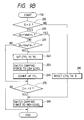
- FIGS. 9A and 9B show a damping force varying routine to be executed repeatedly by the CPU 4a in order to vary the damping forces of the shock absorbers 2FL, 2FR, 2RL, 2RR.
- a vehicle speed S detected by the vehicle speed sensor 3 is read in a step 110, and signals VFL, VFR, VRL, VRR indicative of the rates of change of the damping forces of the shock absorbers 2FL, 2FR, 2RL, 2RR are read from the damping-force rate-of-change detecting circuit 35 in a step 120. Thereafter, the damping forces of the shock absorbers 2FL, 2FR, 2RL, 2RR are varied or switched over in respective steps 130, 140, 150, 160, after which control goes back to the step 110 for repeated execution of the entire process.
- FIG. 9B shows the control procedure for controlling only the damping force of the shock absorber 2FL associated with the front left road wheel 5FL.
- the control procedures for the damping forces of the shock absorbers 2FR, 2RL, 2RR are the same as that shown in FIG. 9B and will not be described.
- a step 200 determines whether the vehicle speed S read in the step 110 is higher than 0, i.e., whether the motor vehicle is running or not. If the motor vehicle is at rest, then control jumps to a step 210 in which a time counter CTFL (described later) is reset to 0, and then control goes to a step 280.
- a time counter CTFL (described later) is reset to 0, and then control goes to a step 280.
- control proceeds to a step 220 which determines whether the damping-force rate-of-change signal VFL read in the step 120 is higher than an upper limit Vref1FL which has been established with respect to the shock absorber 2FL. If VFL ⁇ Vref1FL, then control goes to a step 230 which determines whether the damping-force rate-of-change signal VFL is lower than a lower limit Vref2FL which has also been established with respect to the shock absorber 2FL.
- the upper and lower limits Vref1FL, Vref2FL are threshold values used for detecting bumpy road surfaces from the damping-force rate-of-change signal VFL, and correspond to the present acceleration, described above.
- the time counter CTFL which is set to the soft holding time Ts in the step 240 is counted down at predetermined time intervals until the count reaches 0 according to a predetermined time counting process.
- the time counter CTFL thus counts the soft holding time Ts when it is set to a value corresponding to the soft holding time Ts in the step 240.
- control goes to a step 260 in which a switchover counter CFL which counts the number of switchovers of the damping force is counted up. Then, control goes to a step 270.
- the step 270 determines whether the count of the time counter CTFL is 0 or not.
- the step 270 is also executed if VFL ⁇ Vref2FL in the step 230. More specifically, the time counter CTFL is set to the soft holding time Ts when the damping force changes to a low level, and then counted down according to the time counting process. Therefore, whether the low-level damping force has continued over a period of time longer than Ts can be determined by detecting whether the count of the time counter CTFL is 0 or not.
- step 280 a high-level damping force switchover signal is applied to the charging/discharging circuit 47FL to increase the damping force of the shock absorber 2FL to a high (or hard) level, and the piezoelectric actuator 19FL is de-energized. Then, the process is finished.
- the damping-force rate-of-change signals VFL, VFR, VRL, VRR indicative of the expanding/contracting accelerations of the shock absorbers 2FL, 2FR, 2RL, 2RR are different from each other owing to the different characteristics of the piezoelectric load sensors 31FL, 31FR, 31RL, 31RR and the detectors 41FL, 41FR, 41RL, 41RR, the threshold values, i.e., the upper limits Vref1FL, Vref1FR, Vref1RL, Vref1RR and the lower limits Vref2FL, Vref2FR, Vref2RL, Vref2RR, used for the switching over of the damping forces of the shock absorbers 2FL, 2FR, 2RL, 2RR are corrected so that the damping forces of the shock absorbers 2FL, 2FR, 2RL, 2RR will be varied or switched over at a constant frequency.
- This learning process is executed by the CPU 4a as a timer interrupt routine at predetermined time intervals (each of 10 to 60 sec., for example).
- the average n of counts of the switchover counters CFL, CFR, CRL, CRR which are counted up when the damping forces of the shock absorbers 2FL, 2FR, 2RL, 2RR are switched over in the steps 130 through 160 is calculated in a step 300. Thereafter, the threshold values for the shock absorbers 2FL, 2FR, 2RL, 2RR are corrected based on the average count n and the counts of the switchover counters CFL, CFR, CRL, CRR in respective steps 310 through 340.
- FIG. 10B shows the process of learning the threshold values for the shock absorber 2FL associated with the front left road wheel 5FL in the step 310.
- the processes of learning the threshold values for the other shock absorbers 2FR, 2RL, 2RR are the same as the process of FIG. 10B, they will not be described in detail.
- a step 400 determines whether the count of the switchover counter CFL which represents the number of damping force switchovers with respect to the shock absorber 2FL exceeds the average count n or not, thereby determining whether the frequency at which the damping force of the shock absorber 2FL is switched over is higher than the average frequency at which the damping forces of the shock absorbers 2FL, 2FR, 2RL, 2RR are switched over.
- a preset corrective value ⁇ V1 is added to the upper limit Vref1FL and a preset corrective value ⁇ V2 is subtracted from the lower limit Vref2FL, thus correcting these threshold values.
- control goes to a step 430 which determines whether the count of the switchover counter CFL is smaller than the average count n or not, thereby determining whether the frequency at which the damping force of the shock absorber 2FL is lower than the average frequency at which the damping forces of the shock absorbers 2FL, 2FR, 2RL, 2RR are switched over.
- control proceeds to a step 440 in which the preset corrective value ⁇ V1 is subtracted from the upper limit Vref1FL and the preset corrective value ⁇ V2 is added to the lower limit Vref2FL, thus correcting these threshold values.
- the threshold values Vref1FL, Vref2FL the sensitivity with which bumpy road conditions are detected is increased, thus increasing the frequency at which the damping force of the shock absorber 2FL is switched over.
- control goes to a step 420, which is also executed after the step 410 or 440.
- the switchover counter CFL reset to 0. Thereafter, the process of learning the threshold values for the shock absorber 2FL is finished.
- the threshold value learning process when the frequency at which the damping force of each of the shock absorbers 2FL, 2FR, 2RL, 2RR is switched over in a certain period of time is higher than the average frequency at which the damping forces of the shock absorbers 2FL, 2FR, 2RL, 2RR are switched over, the threshold values are corrected so as to lower the sensitivity with which bumpy road conditions are detected.
- the threshold values are corrected so as to increase the sensitivity with which bumpy road conditions are detected.
- shock absorbers which have a higher damping force switchover frequency are controlled so that the frequency will be progressively lowered, and those shock absorbers which have a lower damping force switchever frequency are controlled so that the frequency will be progressively increased, until finally the damping force switchover frequencies of the shock absorbers 2FL, 2FR, 2RL, 2RR are uniformized.
- the corrective values ⁇ V1, ⁇ V2 for correcting the threshold values i.e., the upper and lower limits Vref1FL, Vref2Fl are of preset values.
- the corrective values ⁇ V1, ⁇ V2 may be determined depending on the difference between the damping force switchover frequency of each shock absorber and the average damping force switchover frequency. According to such a modification, the damping force switchover frequency can be uniformized faster because the upper and lower limits Vref1FL, Vref2FL are corrected to a larger extent as the damping force switchover frequencies of the shock absorbers 2FL, 2FR, 2RL, 2RR are different from each other to a greater extent.
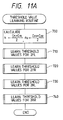
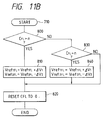
- the threshold values are corrected so that the damping force switchover frequencies of the shock absorbers 2FL, 2FR, 2RL, 2RR are uniformized. Actual roads are usually more bumpy on shoulders than on centers. Therefore, the threshold values for the left and right shock absorbers may independently be corrected as shown in steps 700 through 740 in FIG. 11A and steps 800 through 840 in FIG. 11B. The steps 800 through 840 show the process of correcting the threshold values for the shock absorber 2FL. The threshold values for the shock absorbers 2FR, 2RL, 2RR are also corrected in the same manner as shown in FIG. 11B, using average switchover counts nR, nL, nR, respectively.
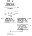
- FIG. 12 shows a process of correcting the threshold values under such circumstances.
- a step 500 calculates an average vehicle speed Sa of the motor vehicle from the previous threshold value learning cycle up to the present threshold value learning cycle.
- a step 510 determines whether the average vehicle speed Sa is equal to or higher than a predetermined speed So (e.g., 60 km/h) or not, thereby determining whether the motor vehicle is running on an express highway or not. If it is determined that the motor vehicle is running on an express highway, then the threshold values (upper and lower limits) are corrected based on the average count of damping force switchovers of all the shock absorbers in a step 520 in the same manner as described above with reference to FIGS. 10A and 10B.
- So e.g. 60 km/h
- the average count of damping force switchovers of the front and rear shock absorbers on each of the left and right sides is determined, and then the threshold values (upper and lower limits) for the front and left shock absorbers on each of the left and right sides are corrected in steps 530, 540.
- the threshold values for the left and right shock absorbers are corrected independently of each other, it may not be necessary to calculate the average count of damping force switchovers of the front and rear shock absorbers on each of the left and right sides. Rather, each time the damping force of one of the front and rear shock absorbers is switched over, it may be confirmed how the damping force of the other shock absorber is switched over, and the threshold values (upper and lower limits) may be corrected for each bump on the road over which the motor vehicle runs.
- a routine for calculating the threshold values as shown in FIG. 13 may repeatedly be executed, together with the damping force switchover process, for the shock absorbers on each of the left and right sides of the motor vehicle.
- a step 600 determines whether the damping force of the front shock absorber is switched over to a low level. If switched over to a low level, then a step 610 determines whether the damping force of the rear shock absorber is also switched over to a low level after the motor vehicle has run over a distance equal to the wheelbase thereof. If not switched over, then a step 620 determines whether the motor vehicle is running straight ahead.
- Vref1F, Vref2F and Vref1R, Vref2R Vref1F(i-1) + ⁇ V
- Vref1F(i) Vref1F(i-1) + ⁇ V
- Vref1R(i) Vref1R(i-1) + ⁇ V
- a step 640 determines whether the damping force of the front shock absorber is switched over to a low level.
- a step 650 determines whether the damping force of the rear shock absorber is also switched over to a low level after the motor vehicle has run over a distance equal to the wheelbase thereof. If not switched over, then a step 660 determines whether the motor vehicle is running straight ahead.
- the steps 630, 670 correct the threshold values for the front and rear shock absorbers after the steps 620, 660 have confirmed that the motor vehicle is running straight ahead.
- the straight running of the motor vehicle may be detected by detecting the steered condition of the steering wheel of the motor vehicle.
- the steered condition may be detected by a steered angle sensor which detects an angle through which the steering wheel is turned.
- the threshold values thus learned may be stored in a backup memory in the electronic controlled 4 so that the stored threshold values will not be erased even after the ignition key is turned off.
- the piezoelectric sensors are incorporated in the respective shock absorbers in the illustrated embodiment, they may be incorporated in only the front left and right shock absorbers.
- the damping forces are switched over according to a process indicated by steps 900 through 940 in FIG. 14A and steps 1000 through 1080 in FIG. 14B, so that the front and rear shock absorbers on each of the left and right sides are commonly controlled.
- the threshold values are learned according to a process indicated by steps 1100 through 1120 in FIG. 15, in which the average count n of damping force switchovers of only the front shock absorbers is determined in the step 1100.
- the steps 1110, 1120 are the same as the process of FIG. 10B.
Landscapes
- Engineering & Computer Science (AREA)
- Mechanical Engineering (AREA)
- Vehicle Body Suspensions (AREA)
Claims (8)
- Système de commande de force d'amortissement (1, 4) pour un véhicule automobile comportant une caisse (7) et des roues (5FL, 5FR, 5RL, 5RR) supportées pour pouvoir tourner sur ladite caisse (7) du véhicule, ledit système comprenant :[a] un amortisseur avant gauche (2FL), avant droit (2FR), arrière gauche (2RL) et arrière droit (2RR), qui sont accouplés entre ladite caisse (7) du véhicule et la roue respective (5FL, 5FR, 5RL, 5RR) et qui ont chacun une force d'amortissement sélectivement variable entre au moins deux valeurs;[b] un moyen de détection (31FL, 31FR, 31RL, 31RR) pour détecter des valeurs représentatives des accélérations d'extension/contraction d'au moins ledit amortisseur avant gauche (2FL) et ledit amortisseur avant droit (2FR);[c] et un moyen de commande (Figure 9B) qui compare les valeurs représentatives des accélérations d'extension/contraction respectivement détectées à des valeurs de référence pré-établies (Vref) et qui, en fonction du résultat de ladite comparaison, fait varier individuellement la force d'amortissement desdits amortisseurs (2FL-2RR);
caractérisé par :[d] un moyen de comparaison (Figure 10A; Figure 11A; Figure 14A) qui :[d1] calcule, dans une période de temps prédéterminée, la fréquence à laquelle la force d'amortissement des amortisseurs (2FL-2RR) pour lesquels les valeurs représentatives de l'accélération d'extension/contraction sont détectées, manoeuvre entre lesdites valeurs de la force d'amortissement, et qui[d2] compare les fréquences calculées à une valeur de référence de fréquence; et[e] un moyen de correction (Figure 10B; Figure 11B; Figure 14B) qui, en fonction du résultat de la comparaison effectuée par ledit moyen de comparaison, corrige lesdites valeurs de référence pour l'accélération (Vref) d'une manière telle que soit :[e1] la fréquence de changement de la force d'amortissement de tous les amortisseurs (2FL-2RR) tend vers la même valeur, soit[e2] les fréquences de changement de la force d'amortissement de l'amortisseur avant gauche (2FL) et de l'amortisseur arrière gauche (2RL) tendent vers la même valeur et, indépendamment de celles-ci, les fréquences de changement de la force d'amortissement des amortisseurs avant droit (2FR) et arrière droit (2RR) tendent vers la même valeur. - Système de commande de force d'amortissement selon la revendication 1, caractérisé en ce que :[a] ledit moyen de détection (31FL, 31FR, 31RL, 31RR) détecte les accélérations d'extension/contraction de tous les amortisseurs (2FL-2RR);[b] ledit moyen de comparaison (Figure 10A) fait la moyenne des fréquences de variation des forces d'amortissement de tous ces amortisseurs (2FL-2RR) et utilise la valeur moyenne comme valeur de référence de fréquence; et[c] ledit moyen de correction (Figure 10B) augmente ou diminue ladite valeur de référence préétablie pour l'accélération (Vref) d'une manière telle que la force d'amortissement de tous les amortisseurs (2FL-2RR) varie à ladite fréquence constante.
- Système de commande de force d'amortissement selon la revendication 1, caractérisé en ce que :[a] ledit moyen de détection (31FL, 31FR, 31RL, 31RR) détecte les accélérations d'extension/contraction de tous les amortisseurs (2FL-2RR);[b] ledit moyen de comparaison (Figure 11A) fait la moyenne des fréquences de variation des forces d'amortissement des amortisseurs avant gauche (2FL) et arrière gauche (2RL) et, indépendamment de celles-ci, des forces d'amortissement des amortisseurs avant droit (2FR) et arrière droit (2RR) et utilise chacune de ces deux valeurs moyennes comme valeur respective de référence de fréquence;[c] et ledit moyen de correction (Figure 11B) augmente ou diminue ladite valeur de référence préétablie pour l'accélération (Vref) d'une manière telle que la force d'amortissement des amortisseurs avant gauche (2FL) et arrière gauche (2RL), et indépendamment de celle-ci, la force d'amortissement des amortisseurs avant droit (2FR) et arrière droit (2RR) est modifiée à une fréquence constante.
- Système de commande de force d'amortissement selon les revendications 2 et 3, caractérisé en ce que le système exécute la commande indiquée en revendication 2, si la vitesse moyenne du véhicule est inférieure à une vitesse prédéterminée (So), alors que la commande indiquée en revendication 3 est exécutée, si la vitesse moyenne du véhicule est supérieure à ladite vitesse prédéterminée (So).
- Système de commande de force d'amortissement selon la revendication 1, caractérisé en ce que :[a] ledit moyen de détection (31FL, 31FR, 31RL, 31RR) détecte les accélérations d'extension/contraction des amortisseurs avant gauche (2FL) et avant droit (2FR);[b] ledit moyen de comparaison (Figure 14A) fait la moyenne des fréquences de variation des forces d'amortissement des amortisseurs avant gauche (2FL) et avant droit (2FR) et utilise cette valeur moyenne comme ladite valeur de référence de fréquence;[c] ledit moyen de correction (Figure 14B) augmente ou diminue ladite valeur de référence préétablie pour l'accélération (Vref) d'une manière telle que la force d'amortissement des amortisseurs avant gauche (2FL) et avant droit (2FR) est modifiée à une fréquence constante;[d] et ledit moyen de commande comprend :[d1] un premier moyen (930) pour faire varier la force d'amortissement des amortisseurs avant gauche (2FL) et avant droit (2FR);[d2] et un second moyen (940) pour faire varier la force d'amortissement des amortisseurs arrière gauche (2RL) et arrière droit (2RR).
- Système de commande de force d'amortissement (1, 4) pour un véhicule automobile comportant une caisse (7) et des roues (5FL, 5FR, 5RL, 5RR) supportées pour pouvoir tourner sur ladite caisse (7) du véhicule, ledit système comprenant :[a] un amortisseur avant gauche (2FL), avant droit (2FR), arrière gauche (2RL) et arrière droit (2RR), qui sont accouplés entre ladite caisse (7) du véhicule et ladite roue respective (5FL, 5FR, 5RL, 5RR) et qui ont chacun une force d'amortissement pouvant varier sélectivement entre au moins deux valeurs;[b] un moyen de détection (31FL, 31FR, 31RL, 31RR) pour détecter des valeurs représentatives des accélérations d'extension/contraction desdits amortisseurs (2FL-2RR);[c] et un moyen de commande (Figure 9B) qui compare les valeurs représentatives de l'accélération d'extension/contraction respectivement détectées à des valeurs de référence pré-établies (Vref) et qui, en fonction du résultat de ladite comparaison, fait varier individuellement la force d'amortissement desdits amortisseurs (2FL-2RR);
caractérisé par :[d] un moyen de comparaison (600, 610, 620, 640, 650, 660) qui compare un état de variation de la force d'amortissement des amortisseurs avant (2FL, 2FR) à une condition de variation de la force d'amortissement des amortisseurs arrière (2RL, 2RR) lorsqu'il y a détection du fait que le véhicule fonctionne d'une façon rectiligne vers l'avant , et[e] un moyen de correction (630, 670) qui corrige lesdites valeurs de référence (Vref) de tous les amortisseurs (2FL-2RR) si le résultat de la comparaison effectuée par ledit moyen de comparaison montre que l'état de variation de la force d'amortissement des amortisseurs avant (2FL, 2FR) n'est pas égale à l'état de la variation de la force d'amortissement des amortisseurs arrière (2RL, 2RR) (Figure 13). - Système de commande de force d'amortissement selon la revendication 6, caractérisé en ce que ledit moyen de comparaison (600, 610, 620, 640, 650, 660) compare l'état de variation de la force d'amortissement des amortisseurs avant (2FL, 2FR) à l'état de variation de la force d'amortissement des amortisseurs arrière (2RL, 2RR) après une période de temps correspondant à la période de temps pendant laquelle le véhicule automobile a besoin de parcourir une distance qui est égale à son empattement.
- Système de commande de force d'amortissement selon la revendication 6 ou 7, caractérisé en ce que ledit état de variation de la force d'amortissement des amortisseurs avant (2FL-2RR) vérifié par ledit moyen de comparaison (600, 610, 620, 640, 650, 660) est un passage de la force d'amortissement vers une valeur plus basse ou plus élevée.
Priority Applications (3)
| Application Number | Priority Date | Filing Date | Title |
|---|---|---|---|
| DE68915442T DE68915442T2 (de) | 1989-08-03 | 1989-08-03 | Kontrollsystem für die Dämpfkraft von Stossdämpfern. |
| EP89114395A EP0411193B1 (fr) | 1989-08-03 | 1989-08-03 | Système pour contrôler la force d'amortissement des amortisseurs de choc |
| US07/391,283 US5142475A (en) | 1989-08-03 | 1989-08-09 | A system for controlling damping force of shock absorbers by adaptively adjusting the desired acceleration expansion/contraction of the shock absorbers |
Applications Claiming Priority (1)
| Application Number | Priority Date | Filing Date | Title |
|---|---|---|---|
| EP89114395A EP0411193B1 (fr) | 1989-08-03 | 1989-08-03 | Système pour contrôler la force d'amortissement des amortisseurs de choc |
Publications (2)
| Publication Number | Publication Date |
|---|---|
| EP0411193A1 EP0411193A1 (fr) | 1991-02-06 |
| EP0411193B1 true EP0411193B1 (fr) | 1994-05-18 |
Family
ID=8201716
Family Applications (1)
| Application Number | Title | Priority Date | Filing Date |
|---|---|---|---|
| EP89114395A Expired - Lifetime EP0411193B1 (fr) | 1989-08-03 | 1989-08-03 | Système pour contrôler la force d'amortissement des amortisseurs de choc |
Country Status (3)
| Country | Link |
|---|---|
| US (1) | US5142475A (fr) |
| EP (1) | EP0411193B1 (fr) |
| DE (1) | DE68915442T2 (fr) |
Families Citing this family (16)
| Publication number | Priority date | Publication date | Assignee | Title |
|---|---|---|---|---|
| GB2239506B (en) * | 1989-12-08 | 1993-08-25 | Toyota Motor Co Ltd | Suspension control system |
| JP3041870B2 (ja) * | 1990-02-16 | 2000-05-15 | トヨタ自動車株式会社 | ショックアブソーバ制御装置 |
| US5321616A (en) * | 1990-08-10 | 1994-06-14 | Matsushita Electric Industrial Co., Ltd. | Vehicle control apparatus |
| JP3107839B2 (ja) * | 1991-02-20 | 2000-11-13 | トキコ株式会社 | 車両用サスペンション装置 |
| DE4112005A1 (de) * | 1991-04-12 | 1992-10-15 | Bosch Gmbh Robert | System zur bildung eines signals bei einem fahrzeug |
| DE4140270A1 (de) * | 1991-12-06 | 1993-06-09 | Robert Bosch Gmbh, 7000 Stuttgart, De | Verfahren und vorrichtung zur fahrwerkregelung |
| JPH06143968A (ja) * | 1992-10-30 | 1994-05-24 | Mitsubishi Motors Corp | サスペンション制御装置 |
| JP3855209B2 (ja) * | 1996-12-09 | 2006-12-06 | 株式会社日立製作所 | サスペンション制御装置 |
| FR2890901B1 (fr) * | 2005-09-22 | 2007-12-14 | Peugeot Citroen Automobiles Sa | Dispositif de commande de suspension, vehicule muni de celui-ci, procede d'obtention et programme. |
| JP4333767B2 (ja) * | 2007-04-03 | 2009-09-16 | 株式会社デンソー | 車両制御装置 |
| US8177041B2 (en) * | 2009-06-23 | 2012-05-15 | Toyota Motor Engineering & Manufacturing North America, Inc. | Damper assemblies and vehicles incorporating the same |
| JP6443316B2 (ja) * | 2015-12-10 | 2018-12-26 | トヨタ自動車株式会社 | 車両用サスペンション制御装置 |
| DE102017118790B4 (de) * | 2017-08-17 | 2019-03-07 | Schaeffler Technologies AG & Co. KG | Wankstabilisator für ein Kraftfahrzeug |
| JP7153620B2 (ja) * | 2019-08-01 | 2022-10-14 | 本田技研工業株式会社 | 電動サスペンション装置 |
| WO2023054038A1 (fr) * | 2021-09-29 | 2023-04-06 | 日立Astemo株式会社 | Système de suspension et dispositif de commande |
| CN115112340B (zh) * | 2022-08-29 | 2022-11-15 | 中国航空工业集团公司沈阳空气动力研究所 | 一种侧滑试验前后置减振器多自由度振动解耦控制方法 |
Family Cites Families (38)
| Publication number | Priority date | Publication date | Assignee | Title |
|---|---|---|---|---|
| GB2068308B (en) * | 1980-01-23 | 1983-09-14 | Lucas Industries Ltd | Control system for vehicle hydraulic suspension |
| JPS59188657U (ja) * | 1983-06-01 | 1984-12-14 | オムロン株式会社 | 圧電素子の駆動回路 |
| JPS59227515A (ja) * | 1983-06-07 | 1984-12-20 | Mazda Motor Corp | 自動車のサスペンシヨン |
| JPS6047709A (ja) * | 1983-08-24 | 1985-03-15 | Mitsubishi Motors Corp | 自動車の懸架装置 |
| JPS60151108A (ja) * | 1984-01-20 | 1985-08-09 | Nissan Motor Co Ltd | 路面状態検出装置 |
| US4770438A (en) * | 1984-01-20 | 1988-09-13 | Nissan Motor Co., Ltd. | Automotive suspension control system with road-condition-dependent damping characteristics |
| JPS60183211A (ja) * | 1984-02-29 | 1985-09-18 | Nissan Motor Co Ltd | 車両用サスペンシヨン装置 |
| JPS60244610A (ja) * | 1984-05-18 | 1985-12-04 | Nippon Denso Co Ltd | シヨツクアブソ−バ制御装置 |
| JPS611518A (ja) * | 1984-06-13 | 1986-01-07 | Honda Motor Co Ltd | サスペンシヨン制御装置 |
| JPS611522A (ja) * | 1984-06-14 | 1986-01-07 | Nissan Motor Co Ltd | 車両におけるサスペンシヨン制御装置 |
| JPS6118513A (ja) * | 1984-07-04 | 1986-01-27 | Nissan Motor Co Ltd | 車両用サスペンシヨン制御装置 |
| US4729459A (en) * | 1984-10-01 | 1988-03-08 | Nippon Soken, Inc. | Adjustable damping force type shock absorber |
| JPS61155010A (ja) * | 1984-10-24 | 1986-07-14 | Nissan Motor Co Ltd | 車両におけるサスペンシヨン制御装置 |
| JPS61108543U (fr) * | 1984-12-20 | 1986-07-09 | ||
| US4717172A (en) * | 1985-02-04 | 1988-01-05 | Olympus Optical Co., Ltd. | Suspension controller |
| DE3518503C1 (de) * | 1985-05-23 | 1986-10-23 | Daimler-Benz Ag, 7000 Stuttgart | Vorrichtung zur rechnergestuetzten,fahrbahnabhaengigen Steuerung von Daempfern einer Fahrzeugfederung |
| JPS61287808A (ja) * | 1985-06-14 | 1986-12-18 | Nissan Motor Co Ltd | 車両のサスペンシヨン制御装置 |
| JPH0741781B2 (ja) * | 1985-10-03 | 1995-05-10 | トヨタ自動車株式会社 | サスペンシヨン制御装置 |
| JPS62167407A (ja) * | 1985-11-30 | 1987-07-23 | Shimadzu Corp | 記録計 |
| JPS62194921A (ja) * | 1986-02-21 | 1987-08-27 | Honda Motor Co Ltd | 緩衝器の減衰力制御方法 |
| JPH0784123B2 (ja) * | 1986-03-24 | 1995-09-13 | 株式会社日本自動車部品総合研究所 | シヨツクアブソ−バの減衰力制御装置 |
| DE3632920A1 (de) * | 1986-09-27 | 1988-03-31 | Bayerische Motoren Werke Ag | Verfahren zur daempfkraftverstellung von kraftfahrzeugen |
| DE3632919A1 (de) * | 1986-09-27 | 1988-03-31 | Bayerische Motoren Werke Ag | Verfahren zur daempfkraftverstellung von kraftfahrzeugen |
| JPH0799488B2 (ja) * | 1986-10-31 | 1995-10-25 | 株式会社豊田中央研究所 | 振動制御装置 |
| JP2575379B2 (ja) * | 1987-03-24 | 1997-01-22 | 日産自動車株式会社 | 能動型サスペンシヨン装置 |
| JPH0829649B2 (ja) * | 1987-03-31 | 1996-03-27 | 日産自動車株式会社 | 能動型サスペンシヨン装置 |
| JPS63251318A (ja) * | 1987-04-09 | 1988-10-18 | Hitachi Ltd | 自動車の走行状況適応サスペンシヨン制御方式 |
| JPS63305014A (ja) * | 1987-06-03 | 1988-12-13 | Nippon Denso Co Ltd | ショックアブソ−バ制御装置 |
| JP2625445B2 (ja) * | 1987-10-09 | 1997-07-02 | 日産自動車株式会社 | 能動型サスペンション |
| JPH0635245B2 (ja) * | 1987-10-15 | 1994-05-11 | 三菱自動車工業株式会社 | 車両用サスペンション装置 |
| JPH01136805A (ja) * | 1987-11-24 | 1989-05-30 | Nissan Motor Co Ltd | 車高制御装置 |
| JP2685200B2 (ja) * | 1988-02-03 | 1997-12-03 | 株式会社デンソー | ピエゾアクチユエータの駆動装置 |
| DE3810638C1 (fr) * | 1988-03-29 | 1989-08-10 | Boge Ag, 5208 Eitorf, De | |
| US4948163A (en) * | 1988-05-31 | 1990-08-14 | Atsugi Motor Parts Company, Limited | Damping characteristics variable hydraulic shock absorber for automotive suspension system with vehicular attitude suppressing capability |
| US4984820A (en) * | 1988-07-22 | 1991-01-15 | Toyota Jidosha Kabushiki Kaisha | Damping force control system for shock absorber variable with frequency of vehicle height difference exceeding limit value |
| JP2946511B2 (ja) * | 1988-07-29 | 1999-09-06 | トヨタ自動車株式会社 | ショックアブソーバの減衰力制御装置 |
| US4861068A (en) * | 1988-08-29 | 1989-08-29 | Colt Industries Inc. | Solenoid valve for programmer vehicle suspension system |
| US4909536A (en) * | 1988-10-24 | 1990-03-20 | Monroe Auto Equipment | Electronic height sensor |
-
1989
- 1989-08-03 DE DE68915442T patent/DE68915442T2/de not_active Expired - Fee Related
- 1989-08-03 EP EP89114395A patent/EP0411193B1/fr not_active Expired - Lifetime
- 1989-08-09 US US07/391,283 patent/US5142475A/en not_active Expired - Fee Related
Non-Patent Citations (1)
| Title |
|---|
| & JP-A-63 305014 (NIPPON DENSO CO LTD) 13 December 1988, * |
Also Published As
| Publication number | Publication date |
|---|---|
| DE68915442T2 (de) | 1995-01-05 |
| EP0411193A1 (fr) | 1991-02-06 |
| US5142475A (en) | 1992-08-25 |
| DE68915442D1 (de) | 1994-06-23 |
Similar Documents
| Publication | Publication Date | Title |
|---|---|---|
| EP0411193B1 (fr) | Système pour contrôler la force d'amortissement des amortisseurs de choc | |
| EP0321078B1 (fr) | Système de détection combinée de la position de la suspension et de la vitesse de la carrosserie pour commande de suspension de véhicule automobile | |
| EP0446637B1 (fr) | Appareil de contrÔle de la force d'amortissement d'un amortisseur de chocs | |
| EP0417695B1 (fr) | Système de contrÔle de suspension | |
| EP0417702B1 (fr) | Système de contrÔle de suspension | |
| EP0442530B1 (fr) | Système de commande d'amortisseurs | |
| EP0397105B1 (fr) | Système de réglage de suspension | |
| JP2634054B2 (ja) | ショックアブソーバの減衰力制御装置 | |
| JP2619902B2 (ja) | ショックアブソーバの減衰力制御装置 | |
| JP2576651B2 (ja) | サスペンション制御装置 | |
| JP2724756B2 (ja) | サスペンション制御装置 | |
| JP2576652B2 (ja) | サスペンション制御装置 | |
| JP3021466B2 (ja) | 車両用サスペンション装置のための制御システム | |
| JP2621512B2 (ja) | サスペンション制御装置 | |
| JP2754809B2 (ja) | サスペンション制御装置 | |
| JPH04244407A (ja) | サスペンション制御装置 | |
| JP2853394B2 (ja) | サスペンション制御装置 | |
| JP2724755B2 (ja) | サスペンション制御装置 | |
| JP2580818B2 (ja) | サスペンション制御装置 | |
| JPH03178820A (ja) | サスペンション制御装置 | |
| JPH03224815A (ja) | サスペンション制御装置 | |
| JPH03266712A (ja) | サスペンション制御装置 | |
| JPH03148319A (ja) | サスペンション制御装置 | |
| JPH03197227A (ja) | サスペンション制御装置 | |
| JPH03271009A (ja) | ショックアブソーバ制御装置 |
Legal Events
| Date | Code | Title | Description |
|---|---|---|---|
| PUAI | Public reference made under article 153(3) epc to a published international application that has entered the european phase |
Free format text: ORIGINAL CODE: 0009012 |
|
| AK | Designated contracting states |
Kind code of ref document: A1 Designated state(s): DE FR GB |
|
| 17P | Request for examination filed |
Effective date: 19910806 |
|
| 17Q | First examination report despatched |
Effective date: 19920903 |
|
| GRAA | (expected) grant |
Free format text: ORIGINAL CODE: 0009210 |
|
| AK | Designated contracting states |
Kind code of ref document: B1 Designated state(s): DE FR GB |
|
| REF | Corresponds to: |
Ref document number: 68915442 Country of ref document: DE Date of ref document: 19940623 |
|
| ET | Fr: translation filed | ||
| PLBE | No opposition filed within time limit |
Free format text: ORIGINAL CODE: 0009261 |
|
| STAA | Information on the status of an ep patent application or granted ep patent |
Free format text: STATUS: NO OPPOSITION FILED WITHIN TIME LIMIT |
|
| 26N | No opposition filed | ||
| REG | Reference to a national code |
Ref country code: GB Ref legal event code: 746 Effective date: 19951016 |
|
| REG | Reference to a national code |
Ref country code: FR Ref legal event code: D6 |
|
| PGFP | Annual fee paid to national office [announced via postgrant information from national office to epo] |
Ref country code: GB Payment date: 19990728 Year of fee payment: 11 |
|
| PGFP | Annual fee paid to national office [announced via postgrant information from national office to epo] |
Ref country code: DE Payment date: 19990809 Year of fee payment: 11 |
|
| PGFP | Annual fee paid to national office [announced via postgrant information from national office to epo] |
Ref country code: FR Payment date: 19990810 Year of fee payment: 11 |
|
| PG25 | Lapsed in a contracting state [announced via postgrant information from national office to epo] |
Ref country code: GB Free format text: LAPSE BECAUSE OF NON-PAYMENT OF DUE FEES Effective date: 20000803 |
|
| GBPC | Gb: european patent ceased through non-payment of renewal fee |
Effective date: 20000803 |
|
| PG25 | Lapsed in a contracting state [announced via postgrant information from national office to epo] |
Ref country code: FR Free format text: LAPSE BECAUSE OF NON-PAYMENT OF DUE FEES Effective date: 20010430 |
|
| PG25 | Lapsed in a contracting state [announced via postgrant information from national office to epo] |
Ref country code: DE Free format text: LAPSE BECAUSE OF NON-PAYMENT OF DUE FEES Effective date: 20010501 |
|
| REG | Reference to a national code |
Ref country code: FR Ref legal event code: ST |