EP0411203B1 - Pistolet de pulvérisation - Google Patents
Pistolet de pulvérisation Download PDFInfo
- Publication number
- EP0411203B1 EP0411203B1 EP89116939A EP89116939A EP0411203B1 EP 0411203 B1 EP0411203 B1 EP 0411203B1 EP 89116939 A EP89116939 A EP 89116939A EP 89116939 A EP89116939 A EP 89116939A EP 0411203 B1 EP0411203 B1 EP 0411203B1
- Authority
- EP
- European Patent Office
- Prior art keywords
- nozzle
- needle
- spray gun
- section
- closure cone
- Prior art date
- Legal status (The legal status is an assumption and is not a legal conclusion. Google has not performed a legal analysis and makes no representation as to the accuracy of the status listed.)
- Expired - Lifetime
Links
- 239000007921 spray Substances 0.000 title claims description 24
- 238000000889 atomisation Methods 0.000 claims description 5
- 239000012530 fluid Substances 0.000 claims 3
- 239000007788 liquid Substances 0.000 description 21
- 238000007789 sealing Methods 0.000 description 4
- 239000012528 membrane Substances 0.000 description 2
- 239000003973 paint Substances 0.000 description 2
- 230000006978 adaptation Effects 0.000 description 1
- 230000000694 effects Effects 0.000 description 1
- 239000003595 mist Substances 0.000 description 1
- 230000000704 physical effect Effects 0.000 description 1
- XLYOFNOQVPJJNP-UHFFFAOYSA-N water Substances O XLYOFNOQVPJJNP-UHFFFAOYSA-N 0.000 description 1
Images
Classifications
-
- B—PERFORMING OPERATIONS; TRANSPORTING
- B05—SPRAYING OR ATOMISING IN GENERAL; APPLYING FLUENT MATERIALS TO SURFACES, IN GENERAL
- B05B—SPRAYING APPARATUS; ATOMISING APPARATUS; NOZZLES
- B05B1/00—Nozzles, spray heads or other outlets, with or without auxiliary devices such as valves, heating means
- B05B1/30—Nozzles, spray heads or other outlets, with or without auxiliary devices such as valves, heating means designed to control volume of flow, e.g. with adjustable passages
- B05B1/3033—Nozzles, spray heads or other outlets, with or without auxiliary devices such as valves, heating means designed to control volume of flow, e.g. with adjustable passages the control being effected by relative coaxial longitudinal movement of the controlling element and the spray head
- B05B1/3073—Nozzles, spray heads or other outlets, with or without auxiliary devices such as valves, heating means designed to control volume of flow, e.g. with adjustable passages the control being effected by relative coaxial longitudinal movement of the controlling element and the spray head the controlling element being a deflector acting as a valve in co-operation with the outlet orifice
-
- B—PERFORMING OPERATIONS; TRANSPORTING
- B05—SPRAYING OR ATOMISING IN GENERAL; APPLYING FLUENT MATERIALS TO SURFACES, IN GENERAL
- B05B—SPRAYING APPARATUS; ATOMISING APPARATUS; NOZZLES
- B05B7/00—Spraying apparatus for discharge of liquids or other fluent materials from two or more sources, e.g. of liquid and air, of powder and gas
- B05B7/02—Spray pistols; Apparatus for discharge
- B05B7/12—Spray pistols; Apparatus for discharge designed to control volume of flow, e.g. with adjustable passages
- B05B7/1254—Spray pistols; Apparatus for discharge designed to control volume of flow, e.g. with adjustable passages the controlling means being fluid actuated
- B05B7/1263—Spray pistols; Apparatus for discharge designed to control volume of flow, e.g. with adjustable passages the controlling means being fluid actuated pneumatically actuated
- B05B7/1272—Spray pistols; Apparatus for discharge designed to control volume of flow, e.g. with adjustable passages the controlling means being fluid actuated pneumatically actuated actuated by gas involved in spraying, i.e. exiting the nozzle, e.g. as a spraying or jet shaping gas
Definitions
- the invention relates to a spray gun with air atomization according to the preamble of claim 1.
- Such a spray gun is known from US-A-3 396 911.
- the closing cone of the needle is arranged outside the nozzle, and the nozzle is opened and closed from the outside with the closing cone.
- the needle is moved by operating the gun actuating lever.
- the feed of the needle is determined by an adjusting screw.
- Conventional air atomizing spray guns which are equipped with a nozzle and a needle, atomize the liquid to be processed using compressed air. Due to the different physical properties of the liquids, many types of nozzle and needle combinations with different bore diameters of the nozzles must be used in order to be able to atomize the large number of liquids optimally.
- the needle In order to adapt the outflow cross section between nozzle and needle to the respective liquid, the needle has an adjustable stroke in known spray guns, with which the outflow cross section between nozzle and needle can be adjusted to a desired size.
- a disadvantage of known spray guns is that the needle is often not seated in the center of the nozzle, which is why the liquid does not flow out of the nozzle evenly and centrally, but in an undesired lateral direction.
- the object of the invention is to improve a spray gun of the type mentioned at the outset in such a way that a uniform central and annular outflow cross section for the liquid is achieved.
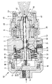
- the spray gun 12 consists of a gun body 4, onto which a cylinder 3 is screwed, which has a connection 14 for the supply of compressed air.
- a nozzle 2 is permanently installed in the gun body 4.
- the nozzle 2 and the gun body 4 have a central bore in which a needle 1 cooperating with the nozzle 2 is arranged to be axially displaceable.
- a piston 6 is installed axially displaceable, which can be acted upon by compressed air from the connection 14.
- a sealing ring 16 is installed between the piston 6 and the cylinder 3.
- the piston 6 has a radial collar which can abut against a stop ring 5, as a result of which the axial path of the piston 6 in the direction of the outflow opening of the spray gun is limited.
- the stop ring 5 sits in an annular groove of the cylinder 3.
- the inner end face of the piston 6 is, as shown, on a flange 18 and between the flange 18 and a disc 32 which is screwed onto the gun body 4, disc springs 10 are installed.
- the flange 18 has a central threaded connector on which one Bush 20 is screwed on, which in turn has a neck or collar 22 which sits on the needle 1 or through which the needle 1 extends.
- the end face of the collar 22 abuts a shoulder 24 of the needle 1.
- the flange 18 has a central axial bore through which the needle 1 extends, on the left, threaded end 28 of which a nut 30 is screwed.
- the flange 18 and the sleeve 20 are thus clamped between the shoulder 24 of the needle 1 and the nut 30 in the axial direction.
- a sealing ring 34 and a sealing membrane 36 are installed between the disk 32 and the gun body 4.
- the needle 1 is mounted centrally in the nozzle 2, which for this purpose has a bearing section 26 which forms a slide bearing for the needle 1.
- the bearing section 26 directly adjoins the outer free end 38 of the nozzle 2, so that the needle 1 is mounted near the outflow opening of the liquid from the spray gun, thereby achieving a relatively precise central mounting of the needle 1 in the nozzle 2.
- At least one axial channel 8 is formed in the bearing section 26 for the flow of the liquid to the outlet opening.
- the needle 1 is equipped at its right end in the drawing with a closing cone 40 which interacts with the end 38 of the nozzle 2.
- the closing cone 40 of the needle 1 is now arranged outside the outer end 38 of the nozzle 2, and together with the end 38 of the nozzle 2 it forms an annular conical outflow cross section 7.
- the end 38 of the nozzle 2 has an end surface which widens conically in the outflow direction and which is opposite the conical surface of the closing cone 40, so that when these are open, between these two conical surfaces Spray gun of the annular conical outflow gap 7 is formed.
- outlet openings 42 open for the atomizing air, through which the liquid emerging from the outflow cross section or outflow gap 7 is atomized.
- a head piece 46 is screwed onto the gun body 4, and suitable channels and outlet openings 44 for so-called horn air are formed in this head piece 46, through which the atomized liquid stream can be brought into a desired shape, for example through the nozzles 44 emerging air can be brought into an elliptical shape.
- suitable channels for the supply and passage of the atomizing air and the horn air are formed in the gun body 4 and in the head piece 46.
- annular channel 52 is formed, into which the liquid to be atomized can be introduced via an inlet connection 50.
- the spray gun according to the invention works as follows.
- the cylinder 3 can be screwed more or less far onto the gun body 4, whereby the stroke of the piston 6 can be adjusted via the stop ring 5. Compressed air is applied to the latter via the connection 14, as a result of which it moves axially to the right in the figure until it strikes the stop ring 5.
- the needle 1 is taken along with this movement and moved axially to the right in the figure, whereby the spray gun is opened, that is, the closing cone 40 which, when the spray gun is closed, on the conical exit surface of the End 38 of the nozzle 2 is seated, detaches from this surface and thereby gives the annular cone Outflow cross section 7 free.
- the stroke of the piston 6 and thus the stroke of the needle 1 relative to the nozzle 2 and thus the size of the outflow cross section 7 can now be set.
- the plate springs 10 are compressed accordingly.
- the liquid flows from the inlet connection 50 through the annular space 52 between the needle 1 and the gun body 4 or nozzle 2 then through the axial channel 8 in the bearing section 26 and then through an annular channel 9 between the nozzle 2 and the end piece of the needle 1.
- This end piece of the needle 1 has a somewhat smaller diameter than the central section, which is guided centrally in the bearing section 26.
- a stop ring 54 which sits in a groove of the collar 22, and which can abut against the disk 32, defines the end position of the bushing 20 and the sealing membrane 36 to the left in the drawing, ie in the closing direction, when the needle 1 is removed.
- the closing cone 40 is arranged outside the outer free end 38 of the nozzle 2, ie opposite this end and cooperating therewith. It opens and closes the nozzle 2.
- no liquid for example a paint
- the color to be processed remains liquid anyway within the outlet gap 7.
- the spray gun is not opened in the inward direction as before, but in the outward direction, which inevitably releases the set discharge cross-section 7 for the liquid.
- the direction of movement of the needle 1 is identical to the direction of the liquid flow, as a result of which the liquid flows out is positively influenced when opening the gun.
- the central guidance of the needle 1 in the nozzle 2 with the aid of the bearing section 26 results in a uniform, central discharge of the liquid from the nozzle, which has an advantageous effect on atomization.
- the adjustment or the setting of the outflow cross-section 7 between the nozzle 2 and the nose 1 takes place, as stated above, by correspondingly rotating the cylinder 3 relative to the gun body 4, whereby the former is more or less screwed onto the latter and thus the stroke of the Piston 6 is set.
- the adjustable ring cone shape of the liquid flow between the nozzle 2 and the needle 1 enables a very good adaptation of the liquid flow to the atomizing air, which has the advantage that with relatively low air pressure and relatively low air volume, optimal atomization is possible with only minimal spray mist.
- the invention allows more economical atomization of air for many types of liquids with high surface tensions, such as, in particular, water-based paints.
Landscapes
- Nozzles (AREA)
Claims (5)
- Pistolet de pulvérisation à pulvérisation d'air, comprenant un boîtier muni d'une buse (2) et une aiguille (1) pouvant être déplacée axialement qui présente un cône de fermeture (40) coopérant avec la buse, comprenant en outre, entre la buse (2) et le cône de fermeture (40), une section d'écoulement réglable, le cône de fermeture (40) de l'aiguille (1) étant disposé contre l'extrémité extérieure libre (38) de la buse (2) qui, à cette extrémité extérieure libre (38), peut être ouverte ou fermée par le cône de fermeture (40) de l'aiguille (1), l'orifice de l'aiguille (1) se situant dans le sens d'écoulement du flux de liquide et l'aiguille (1) étant montée de manière centrée dans la buse (2), caractérisé en ce que la buse (2) est munie d'un logement (26) pour l'aiguille (1) dans lequel est réalisé au moins un canal (8) axial pour le passage du liquide.
- Pistolet de pulvérisation selon la revendication 1, caractérisé en ce que la section d'écoulement (7) entre l'extrémité (38) de la buse (2) et le cône de fermeture (40) peut être déplacée en continu vers l'extérieur dans la direction du flux de liquide.
- Pistolet de pulvérisation selon la revendication 2, caractérisé en ce que la section d'écoulement (7) a une forme conique annulaire s'élargissant dans le sens de l'écoulement.
- Pistolet de pulvérisation selon l'une des revendications précédentes, caractérisé en ce que l'aiguille (1) peut être déplacée axialement et réglée au moyen d'un piston (6) pouvant être actionné par air comprimé.
- Pistolet de pulvérisation selon la revendication 4, caractérisé en ce que la course du piston (6) et donc la section d'écoulement (7) entre la buse et le cône de fermeture peuvent être réglées au moyen d'une bague de butée (5) mobile axialement.
Applications Claiming Priority (2)
| Application Number | Priority Date | Filing Date | Title |
|---|---|---|---|
| DE3925931 | 1989-08-04 | ||
| DE3925931A DE3925931A1 (de) | 1989-08-04 | 1989-08-04 | Spritzpistole |
Publications (3)
| Publication Number | Publication Date |
|---|---|
| EP0411203A2 EP0411203A2 (fr) | 1991-02-06 |
| EP0411203A3 EP0411203A3 (en) | 1991-10-23 |
| EP0411203B1 true EP0411203B1 (fr) | 1993-08-11 |
Family
ID=6386567
Family Applications (1)
| Application Number | Title | Priority Date | Filing Date |
|---|---|---|---|
| EP89116939A Expired - Lifetime EP0411203B1 (fr) | 1989-08-04 | 1989-09-13 | Pistolet de pulvérisation |
Country Status (6)
| Country | Link |
|---|---|
| EP (1) | EP0411203B1 (fr) |
| JP (1) | JPH03114559A (fr) |
| AU (1) | AU6004890A (fr) |
| BR (1) | BR9003801A (fr) |
| CA (1) | CA2021970A1 (fr) |
| DE (2) | DE3925931A1 (fr) |
Families Citing this family (6)
| Publication number | Priority date | Publication date | Assignee | Title |
|---|---|---|---|---|
| JP2002361118A (ja) * | 2001-06-12 | 2002-12-17 | Rita System Kk | 塗料供給用流量調節弁 |
| JP4851158B2 (ja) * | 2005-02-23 | 2012-01-11 | 旭サナック株式会社 | 塗装用エアスプレイ装置 |
| DE102009020077A1 (de) | 2009-05-06 | 2010-11-11 | Dürr Systems GmbH | Beschichtungsmittelvorrichtung und Beschichtungsvorrichtung |
| DE102013003897B4 (de) * | 2013-03-06 | 2017-08-03 | Audi Ag | Düsenträger für die Befestigung einer Lackierdüse an einer Lackzerstäubereinrichtung und Lackzerstäubereinrichtung mit einem solchen Düsenträger |
| WO2015109384A1 (fr) | 2014-01-27 | 2015-07-30 | Her Majesty The Queen In Right Of Canada As Represented By The Minister Of Natural Resources | Procédé de séchage et de réduction en poudre d'aliments fonctionnels, de produits nutraceutiques et d'ingrédients santé naturels |
| JP6531939B2 (ja) * | 2015-04-09 | 2019-06-19 | アネスト岩田株式会社 | 自動スプレーガン |
Family Cites Families (3)
| Publication number | Priority date | Publication date | Assignee | Title |
|---|---|---|---|---|
| US3059859A (en) * | 1958-10-30 | 1962-10-23 | Arleigh G Hupp | Spraying apparatus |
| BE649073A (fr) * | 1963-07-17 | 1964-10-01 | ||
| US3396911A (en) * | 1964-01-27 | 1968-08-13 | Edward O. Norris | Spray gun activation mechanism |
-
1989
- 1989-08-04 DE DE3925931A patent/DE3925931A1/de not_active Withdrawn
- 1989-09-13 EP EP89116939A patent/EP0411203B1/fr not_active Expired - Lifetime
- 1989-09-13 DE DE8989116939T patent/DE58905285D1/de not_active Expired - Fee Related
-
1990
- 1990-07-25 CA CA002021970A patent/CA2021970A1/fr not_active Abandoned
- 1990-07-31 AU AU60048/90A patent/AU6004890A/en not_active Abandoned
- 1990-08-02 BR BR909003801A patent/BR9003801A/pt unknown
- 1990-08-03 JP JP2206639A patent/JPH03114559A/ja active Pending
Also Published As
| Publication number | Publication date |
|---|---|
| JPH03114559A (ja) | 1991-05-15 |
| BR9003801A (pt) | 1991-09-03 |
| AU6004890A (en) | 1991-02-07 |
| CA2021970A1 (fr) | 1991-02-05 |
| EP0411203A3 (en) | 1991-10-23 |
| DE58905285D1 (de) | 1993-09-16 |
| EP0411203A2 (fr) | 1991-02-06 |
| DE3925931A1 (de) | 1991-02-07 |
Similar Documents
| Publication | Publication Date | Title |
|---|---|---|
| DE69211891T2 (de) | Verteilerscheibe für Hochdurchfluss-Niederdruck-Sprühpistole | |
| DE68924079T2 (de) | Sprühpistole. | |
| DE4230535C2 (de) | Zweikomponenten-Spritzpistole | |
| EP0706832B1 (fr) | Pistolet de pulvérisation de peinture à air comprimé | |
| DE1577919C3 (de) | Elektrostatisch arbeitende Farbspritzvorrichtung mit einstellbarem Öffnungswinkel des Farbnebelkegels | |
| DE69214345T2 (de) | Elektrostatische Sprühpistole mit hoher Spannung und niedrigem Druck | |
| DE69530275T2 (de) | Spritzpistole mit einstellbarem Abgabeventil | |
| DE2737680C3 (de) | Spritzpistole | |
| DE69508734T2 (de) | Sprühvorrichtung mit veränderlicher Sprühstrahlform | |
| DE1063989B (de) | Drallduese | |
| DE69723362T2 (de) | Homogenisierventil | |
| EP2929944A1 (fr) | Dispositif de pulvérisation de couleur | |
| DE2646719A1 (de) | Spritzpistole | |
| DE10233198A1 (de) | Rotationszerstäuber | |
| EP0411203A2 (fr) | Pistolet de pulvérisation | |
| DE2757522C2 (de) | Rund- oder Ringstrahldüse zum Erzeugen und Abstrahlen eines Nebels oder Aerosols zur Beschichtung von Gegenständen | |
| EP0479020A1 (fr) | Valve pour convertir de la vapeur avec entraînement de la broche | |
| DE2500359A1 (de) | Zerstaeuber | |
| DE3871805T2 (de) | Pulverspritzpistole. | |
| EP0497255A2 (fr) | Buse de débit pour milieux | |
| EP2251091A2 (fr) | Buse de rotor | |
| DE102020115174A1 (de) | Spritzpistole, insbesondere Farbspritzpistole | |
| DE4228360A1 (de) | Kraftstoff-Einspritzdüse für Brennkraftmaschinen | |
| DE2042690A1 (de) | Pumpenzerstauber, insbesondere auf ein Gefäß aufsetzbare Zerstäuberpistole | |
| DE8909443U1 (de) | Spritzpistole |
Legal Events
| Date | Code | Title | Description |
|---|---|---|---|
| PUAI | Public reference made under article 153(3) epc to a published international application that has entered the european phase |
Free format text: ORIGINAL CODE: 0009012 |
|
| AK | Designated contracting states |
Kind code of ref document: A2 Designated state(s): BE DE FR GB IT |
|
| PUAL | Search report despatched |
Free format text: ORIGINAL CODE: 0009013 |
|
| AK | Designated contracting states |
Kind code of ref document: A3 Designated state(s): BE DE FR GB IT |
|
| RAP1 | Party data changed (applicant data changed or rights of an application transferred) |
Owner name: ITW OBERFLAECHENTECHNIK GMBH |
|
| 17P | Request for examination filed |
Effective date: 19920408 |
|
| 17Q | First examination report despatched |
Effective date: 19920622 |
|
| GRAA | (expected) grant |
Free format text: ORIGINAL CODE: 0009210 |
|
| AK | Designated contracting states |
Kind code of ref document: B1 Designated state(s): BE DE FR GB IT |
|
| ITF | It: translation for a ep patent filed | ||
| REF | Corresponds to: |
Ref document number: 58905285 Country of ref document: DE Date of ref document: 19930916 |
|
| RAP2 | Party data changed (patent owner data changed or rights of a patent transferred) |
Owner name: ABB FLAEKT, INC. |
|
| ET | Fr: translation filed | ||
| GBT | Gb: translation of ep patent filed (gb section 77(6)(a)/1977) |
Effective date: 19931025 |
|
| PLBE | No opposition filed within time limit |
Free format text: ORIGINAL CODE: 0009261 |
|
| STAA | Information on the status of an ep patent application or granted ep patent |
Free format text: STATUS: NO OPPOSITION FILED WITHIN TIME LIMIT |
|
| REG | Reference to a national code |
Ref country code: GB Ref legal event code: 732E |
|
| 26N | No opposition filed | ||
| PGFP | Annual fee paid to national office [announced via postgrant information from national office to epo] |
Ref country code: GB Payment date: 19970812 Year of fee payment: 9 |
|
| PGFP | Annual fee paid to national office [announced via postgrant information from national office to epo] |
Ref country code: FR Payment date: 19970917 Year of fee payment: 9 |
|
| PGFP | Annual fee paid to national office [announced via postgrant information from national office to epo] |
Ref country code: DE Payment date: 19971001 Year of fee payment: 9 |
|
| PGFP | Annual fee paid to national office [announced via postgrant information from national office to epo] |
Ref country code: BE Payment date: 19971007 Year of fee payment: 9 |
|
| PG25 | Lapsed in a contracting state [announced via postgrant information from national office to epo] |
Ref country code: GB Free format text: LAPSE BECAUSE OF NON-PAYMENT OF DUE FEES Effective date: 19980913 |
|
| PG25 | Lapsed in a contracting state [announced via postgrant information from national office to epo] |
Ref country code: BE Free format text: LAPSE BECAUSE OF NON-PAYMENT OF DUE FEES Effective date: 19980930 |
|
| BERE | Be: lapsed |
Owner name: ABB FL?K INC. Effective date: 19980930 |
|
| GBPC | Gb: european patent ceased through non-payment of renewal fee |
Effective date: 19980913 |
|
| PG25 | Lapsed in a contracting state [announced via postgrant information from national office to epo] |
Ref country code: FR Free format text: LAPSE BECAUSE OF NON-PAYMENT OF DUE FEES Effective date: 19990531 |
|
| PG25 | Lapsed in a contracting state [announced via postgrant information from national office to epo] |
Ref country code: DE Free format text: LAPSE BECAUSE OF NON-PAYMENT OF DUE FEES Effective date: 19990701 |
|
| REG | Reference to a national code |
Ref country code: FR Ref legal event code: ST |
|
| PG25 | Lapsed in a contracting state [announced via postgrant information from national office to epo] |
Ref country code: IT Free format text: LAPSE BECAUSE OF NON-PAYMENT OF DUE FEES;WARNING: LAPSES OF ITALIAN PATENTS WITH EFFECTIVE DATE BEFORE 2007 MAY HAVE OCCURRED AT ANY TIME BEFORE 2007. THE CORRECT EFFECTIVE DATE MAY BE DIFFERENT FROM THE ONE RECORDED. Effective date: 20050913 |