EP0411319A2 - Moteur à combustion interne pour véhicule automobile avec paliers de villebrequin et d'arbre d'entraînement - Google Patents
Moteur à combustion interne pour véhicule automobile avec paliers de villebrequin et d'arbre d'entraînement Download PDFInfo
- Publication number
- EP0411319A2 EP0411319A2 EP90112311A EP90112311A EP0411319A2 EP 0411319 A2 EP0411319 A2 EP 0411319A2 EP 90112311 A EP90112311 A EP 90112311A EP 90112311 A EP90112311 A EP 90112311A EP 0411319 A2 EP0411319 A2 EP 0411319A2
- Authority
- EP
- European Patent Office
- Prior art keywords
- crankshaft
- internal combustion
- combustion engine
- output shaft
- gear
- Prior art date
- Legal status (The legal status is an assumption and is not a legal conclusion. Google has not performed a legal analysis and makes no representation as to the accuracy of the status listed.)
- Granted
Links
Images






Classifications
-
- F—MECHANICAL ENGINEERING; LIGHTING; HEATING; WEAPONS; BLASTING
- F02—COMBUSTION ENGINES; HOT-GAS OR COMBUSTION-PRODUCT ENGINE PLANTS
- F02F—CYLINDERS, PISTONS OR CASINGS, FOR COMBUSTION ENGINES; ARRANGEMENTS OF SEALINGS IN COMBUSTION ENGINES
- F02F7/00—Casings, e.g. crankcases
- F02F7/0002—Cylinder arrangements
- F02F7/0007—Crankcases of engines with cylinders in line
-
- F—MECHANICAL ENGINEERING; LIGHTING; HEATING; WEAPONS; BLASTING
- F01—MACHINES OR ENGINES IN GENERAL; ENGINE PLANTS IN GENERAL; STEAM ENGINES
- F01L—CYCLICALLY OPERATING VALVES FOR MACHINES OR ENGINES
- F01L1/00—Valve-gear or valve arrangements, e.g. lift-valve gear
- F01L1/02—Valve drive
- F01L1/022—Chain drive
-
- F—MECHANICAL ENGINEERING; LIGHTING; HEATING; WEAPONS; BLASTING
- F02—COMBUSTION ENGINES; HOT-GAS OR COMBUSTION-PRODUCT ENGINE PLANTS
- F02B—INTERNAL-COMBUSTION PISTON ENGINES; COMBUSTION ENGINES IN GENERAL
- F02B61/00—Adaptations of engines for driving vehicles or for driving propellers; Combinations of engines with gearing
- F02B61/06—Combinations of engines with mechanical gearing
-
- F—MECHANICAL ENGINEERING; LIGHTING; HEATING; WEAPONS; BLASTING
- F02—COMBUSTION ENGINES; HOT-GAS OR COMBUSTION-PRODUCT ENGINE PLANTS
- F02F—CYLINDERS, PISTONS OR CASINGS, FOR COMBUSTION ENGINES; ARRANGEMENTS OF SEALINGS IN COMBUSTION ENGINES
- F02F1/00—Cylinders; Cylinder heads
- F02F1/24—Cylinder heads
- F02F1/42—Shape or arrangement of intake or exhaust channels in cylinder heads
- F02F1/4214—Shape or arrangement of intake or exhaust channels in cylinder heads specially adapted for four or more valves per cylinder
- F02F1/4221—Shape or arrangement of intake or exhaust channels in cylinder heads specially adapted for four or more valves per cylinder particularly for three or more inlet valves
-
- F—MECHANICAL ENGINEERING; LIGHTING; HEATING; WEAPONS; BLASTING
- F01—MACHINES OR ENGINES IN GENERAL; ENGINE PLANTS IN GENERAL; STEAM ENGINES
- F01L—CYCLICALLY OPERATING VALVES FOR MACHINES OR ENGINES
- F01L1/00—Valve-gear or valve arrangements, e.g. lift-valve gear
- F01L1/02—Valve drive
- F01L1/026—Gear drive
-
- F—MECHANICAL ENGINEERING; LIGHTING; HEATING; WEAPONS; BLASTING
- F01—MACHINES OR ENGINES IN GENERAL; ENGINE PLANTS IN GENERAL; STEAM ENGINES
- F01L—CYCLICALLY OPERATING VALVES FOR MACHINES OR ENGINES
- F01L1/00—Valve-gear or valve arrangements, e.g. lift-valve gear
- F01L1/02—Valve drive
- F01L1/04—Valve drive by means of cams, camshafts, cam discs, eccentrics or the like
- F01L1/047—Camshafts
- F01L1/053—Camshafts overhead type
- F01L2001/0537—Double overhead camshafts [DOHC]
-
- F—MECHANICAL ENGINEERING; LIGHTING; HEATING; WEAPONS; BLASTING
- F01—MACHINES OR ENGINES IN GENERAL; ENGINE PLANTS IN GENERAL; STEAM ENGINES
- F01M—LUBRICATING OF MACHINES OR ENGINES IN GENERAL; LUBRICATING INTERNAL COMBUSTION ENGINES; CRANKCASE VENTILATING
- F01M1/00—Pressure lubrication
- F01M1/12—Closed-circuit lubricating systems not provided for in groups F01M1/02 - F01M1/10
- F01M2001/126—Dry-sumps
-
- F—MECHANICAL ENGINEERING; LIGHTING; HEATING; WEAPONS; BLASTING
- F02—COMBUSTION ENGINES; HOT-GAS OR COMBUSTION-PRODUCT ENGINE PLANTS
- F02B—INTERNAL-COMBUSTION PISTON ENGINES; COMBUSTION ENGINES IN GENERAL
- F02B1/00—Engines characterised by fuel-air mixture compression
- F02B1/02—Engines characterised by fuel-air mixture compression with positive ignition
- F02B1/04—Engines characterised by fuel-air mixture compression with positive ignition with fuel-air mixture admission into cylinder
-
- F—MECHANICAL ENGINEERING; LIGHTING; HEATING; WEAPONS; BLASTING
- F02—COMBUSTION ENGINES; HOT-GAS OR COMBUSTION-PRODUCT ENGINE PLANTS
- F02B—INTERNAL-COMBUSTION PISTON ENGINES; COMBUSTION ENGINES IN GENERAL
- F02B75/00—Other engines
- F02B75/16—Engines characterised by number of cylinders, e.g. single-cylinder engines
- F02B75/18—Multi-cylinder engines
- F02B2075/1804—Number of cylinders
- F02B2075/1824—Number of cylinders six
-
- F—MECHANICAL ENGINEERING; LIGHTING; HEATING; WEAPONS; BLASTING
- F02—COMBUSTION ENGINES; HOT-GAS OR COMBUSTION-PRODUCT ENGINE PLANTS
- F02B—INTERNAL-COMBUSTION PISTON ENGINES; COMBUSTION ENGINES IN GENERAL
- F02B2275/00—Other engines, components or details, not provided for in other groups of this subclass
- F02B2275/18—DOHC [Double overhead camshaft]
-
- F—MECHANICAL ENGINEERING; LIGHTING; HEATING; WEAPONS; BLASTING
- F02—COMBUSTION ENGINES; HOT-GAS OR COMBUSTION-PRODUCT ENGINE PLANTS
- F02F—CYLINDERS, PISTONS OR CASINGS, FOR COMBUSTION ENGINES; ARRANGEMENTS OF SEALINGS IN COMBUSTION ENGINES
- F02F1/00—Cylinders; Cylinder heads
- F02F1/24—Cylinder heads
- F02F2001/244—Arrangement of valve stems in cylinder heads
- F02F2001/245—Arrangement of valve stems in cylinder heads the valve stems being orientated at an angle with the cylinder axis
-
- F—MECHANICAL ENGINEERING; LIGHTING; HEATING; WEAPONS; BLASTING
- F05—INDEXING SCHEMES RELATING TO ENGINES OR PUMPS IN VARIOUS SUBCLASSES OF CLASSES F01-F04
- F05C—INDEXING SCHEME RELATING TO MATERIALS, MATERIAL PROPERTIES OR MATERIAL CHARACTERISTICS FOR MACHINES, ENGINES OR PUMPS OTHER THAN NON-POSITIVE-DISPLACEMENT MACHINES OR ENGINES
- F05C2201/00—Metals
- F05C2201/02—Light metals
- F05C2201/021—Aluminium
Definitions
- the present invention relates to an internal combustion engine for automotive vehicles comprising a crankshaft having an output gear and a power output shaft disposed in parallel to the crankshaft adapted to distribute the output power of the crankshaft to clutch and/or transmission means and/or accessory equipment.
- the present invention refers to a multi-cylinder engine having a compacted structure due to the provision of an output power shaft rotatably supported on the same side and above the crankshaft which is in engagement with said output shaft in order to transmit output power to a flywheel associated to a manually operable transmission means or a torque converter of an automatic transmission, associated to one end of the output shaft.
- the internal combustion engine comprises a fly wheel which, instead of being supported by the crankshaft itself, could be disposed on one end of an output shaft which is disposed slightly above the crankshaft on the same side of the engine block and is driven by the crankshaft. In this way, it becomes possible to shorten the extent of the engine in the direction of the crankshaft axis.
- the output shaft is rotatably supported slightly above the crankshaft and, moreover, serves to drive a plurality of other systems and auxiliary equipment such as alternator, oil and water pump means and the intake and exhaust valve operating cam mechanism.
- auxiliary equipment such as alternator, oil and water pump means and the intake and exhaust valve operating cam mechanism.
- an improved engine structure should be developed enabling to gain the merits of a reduced length of the engine block in the axial direction of the crankshaft while preventing the transmission in between the crankshaft and the output shaft from generating undesirable gear noise.
- crankshaft for a straight-type multi-cylinder engine a pair of crankarms supporting the associated crankpin for each cylinder (which, in turn, supports the connecting rod, respectively) is designed as a counterweight so that the reciprocational and rotational balances for each cylinder may be obtained.
- all counterweights can be of identical shape.
- an internal combustion engine as indicated in the introductory portion of the description is characterized in that the crankshaft and the output shaft both are supported by a common integral unitary bearing structure.
- the bearing structure for journaling the crankshaft and the power output shaft is composed of an upper half which preferably is integral with the crankcase of the engine providing a unitary cylinder block structure, and a lower half which is bolted to the upper half and associated cylinder block structure wherein the upper and lower halves each form an integral bearing structure for rotatably supporting the crankshaft and the output shaft.
- the crankshaft supported by the upper and lower halves of the unitary bearing structure, has a pair of crankarms for each cylinder wherein each pair of crankarms is composed of a disk and a counterweight with a crankpin in between. Moreover, one of the disk-shaped crankarms is designed to form a gear which forms an output gear of the camshaft which is in mesh with a counter-gear of the output shaft.
- the present invention provides for the crankshaft and power output shaft to be supported integrally by an upper and lower half of the bearing structure, the rigidity of the bearing portion rotatably supporting the crankshaft and the power output shaft can be improved. Accordingly, even if a big stress is applied on the bearing portion of the crankshaft and/or the output shaft, a positional offset in between both shafts can be minimized to maintain an appropriate backlash in between the output gear of the crankshaft and the counter-gear of the output shaft, thus, preventing seizure of the gears and undesirable gear noise generation to occur.
- the advantageous embodiment of the present invention concerning the design of the crankarm structure of the crankshaft enables to increase the thickness of the output gear of the crankshaft in order to provide a smoothly operating gear transmission in between the crankshaft and the output shaft.
- all the counterweight can be of identical shape facilitating the manufacturing of the crankshaft and, moreover, the balances of the cylinders can be assured even though one of the crankarms is designed to form an output gear which is in mesh with a counter-gear of the crankshaft.
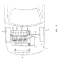
- the reference number 1 denotes the engine compartment of an automobile formed above and between the right and left front wheels 3 connected through front wheel shafts 2.
- an engine unit 4 having a 4-stroke 6-cylinder internal combustion engine with its radiator 5 arranged in front of this engine unit 4.
- the passenger compartment has been made spacious by disposing the engine crankshaft 6 laterally of the vehicle.
- the cylinder block 7 is composed of a crankcase 7a and a cylinder body 7b integrally formed with cast iron.
- the pistons 9 provided in the cylinder body 7b are each connected with the crankshaft 6 through respective connecting rod 10.
- On the cylinder block 7 is mounted a cylinder head 11 provided with a head cover 12, and an ignition plug is provided on each cylinder.
- the cylinder bank of the engine is inclined backwardly relative to the vertical of the vehicle.
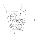
- the power output shaft 16 for distributing the output power of the crankshaft 6 is disposed in parallel with the crankshaft 6 and is disposed slantly forwardly above and close to the crankshaft 6.
- the oil tank 15 reserving engine oil is located slantly forwardly under the crankshaft 6 and the output shaft 16 and is thus faced forwardly of the vehicle as shown by the arrow mark FWD in Figure 3.
- the ouput shaft 16 is positioned in such a manner that the angle ⁇ formed between the cylinder axis plane L1 and the plane L2 including both of the crankshaft 6 axis and the power takeout shaft 16 axis may be an acute angle.
- crankshaft 6 has an output gear 28 formed around one of its crankarms, and this gear 28 is in engagement with a counter-gear 29 mounted on the power takeout shaft 16. Further, a gear 30 provided on the power takeout shaft 16 is connected with a gear 32 on the countershaft 31 journaled on the cylinder head 11 through a first chain 33.
- the gear 34 mounted on the countershaft 31 is connected to the gear 38 on the camshaft 37 is rotated by the rotation of the crankshaft 6, and the cams 39 are rotated together with the camshaft 37 and operate the intake and exhaust valves (not shown) with predetermined timings.
- a flywheel 45 and a clutch mechanism (not shown) so that the power may be transmitted to the front wheel shafts 2 for front wheels 3 through a transmission 47 constituting a manual transmission.
- the flywheel 45 is positioned at one end of the crankcase 7a longitudinally of the crankshaft in such a manner that it will not project outwardly of this crankcase end.
- the primary side of the transmission 47 is disposed on the power takeout shaft 16, and the secondary side is disposed on a countershaft 48 to rotate the front wheel shaft 2 through a gear 49 provided on the wheel shaft 2.
- auxiliary drive pulley 50 On the other end of the output shaft 16 is provided an auxiliary drive pulley 50 as shown in figure 7, which pulley 50 is accomodated within a concave 51 formed laterally on the crank bearing 60 of the crankcase 7a so that it may not project outwardly of this crankcase end.
- a belt 55 is wrapped around this auxiliary drive pulley 50 and the auxiliary pulleys for auxiliaries such as alternator 52, power steering pump 53, air compressor 54, etc., so that these auxiliaries are simultaneously driven by the rotation of the power output shaft 16.
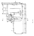
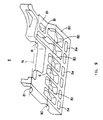
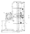
- the bearing portion for journaling the crankshaft 6 and the power takeout shaft 16 is composed of an upper half 70 formed integrally with the crankcase 7a and a lower half 8, and the upper half 70 and the lower half 8 integrally journal each of the crankshaft 6 and the power takeout shaft 16.
- the upper half 70 has bearings 60 for the crankshaft 6 formed for each cylinder, bearings 61 for the power takeout shaft 16, and further openings 62 for the oil passage 223 formed on its bottom side.
- the upper half 70 may be formed as a separate member although it is formed integrally with the crankcase 7a in this embodiment.
- the lower half 8 is made of cast iron, and has bearings 80 for the crankshaft 6, bearings 81 for the power takeout shaft 16, and further oil passage openings 8a formed on its bottom side.
- this lower half 8 is fastened singly on the cylinder block 7 on which is integrally formed the upper half 70 through mounting bolts 400 at twenty-two points, and the oil pan 14 is fastened on the upper half 70 together with the lower half 8 through mounting bolts 401 at fifteen points, and further is fastened singly on the lower half 8 through mounting bolts 402 at five points.
- the axial length of a bearing section (X;X′) of the upper and lower halves 70;8 respectively adapted to rotatably supporting the output shaft 16 is designed to be shorter than the length of a bearing section (Y;Y′) of the upper and lower halves 70;8 respectively adapted to rotatably support the crankshaft 6.
- the output shaft bearing structure is more lightweight than the crankshaft bearing structure.
- the afore-indicated design considerations render it possible to make the journal caps compact and lightweight.
- the assembly of the bearing structure is facilitated as the heavier crankshaft supporting portion Y;Y′ is arranged lower than the lighter output shaft supporting portion. Thus, it is easy to affix the journal caps to the engine.
- the bearing section X for rotatably supporting the output shaft 16 which is designed to be integral with the upper half 70 is shorter than the cooperating bearing section X′ for rotatably supporting the output shaft 16 which is integrally provided at the lower half 8.
- the crankshaft 6 and the power takeout shaft 16 can be left journaled by the lower half 8 even when the oil pan is removed for maintenance operations such as renewal of the strainer 25, which serves to facilitate engine maintenance operations.
- crankshaft 6 and the power takeout shaft 16 are integrally journaled by the bearing portion composed of the upper half 70 and the lower half 8 as described above, the rigidity of the bearing portion is increased. Therefore, positional offset is restrained from occurring between the crankshaft 6 and the power takeout shaft 16 even when being subjected to greater stress transmitted to the bearing portion of the shafts 6,16 and the fluctuation of the backlash provided between the gears 28 and 29 on the crankshaft 6 and the output shaft 16, respectively, can be restrained.
- gears 28 and 29 can be kept appropriate even when the flywheel is provided on the output shaft 16 and, therefore, the rotational speed fluctuation of the crankshaft 6 is transmitted to the output shaft 16 without being relieved. Then, noise occurrence between gears 28 and 29 can be reduced.
- the distance of the bearing 80 for the crankshaft 6 and the bearing 81 for the power takeout shaft 16 can also be restrained from getting increased by the deformation of the lower half 8 caused by the effect of the engine heat, and thus the backlash between gears 28 and 29 on the crankshaft 6 and the power takeout shaft 16, respectively, can be kept appropriate.
- the oil pan 14 and the oil tank 15 are both formed of aluminium casting, and are partitioned from each other by a wall portion 14a, and the oil pan 15 is mounted on the tank mounting seat 14k of the oil pan 14.
- This pump unit P is a pump unit having a discharge pump for sending the oil collected in the crank chamber A to the oil tank 15 and a oil feeding pump for supplying the oil collected in the oil tank 15 to various portions of the engine combined integrally with each other.
- This pump unit P is mounted on the pump mounting portion B formed on the oil pan 14 and on the pump mounting portion C formed on the upper half 70 and the lower half 8.
- the oil passages for communicating the discharge pump and the oil feeding pump with the oil pan 14 and the oil tank 15 are formed integrally with the oil pan 14.
- Figure 11 is a partial sectional view of a vehicle engine unit showing another embodiment.
- the engine unit is provided with an automatic transmission.
- the description of the engine is not repeated.
- a drive plate 500 On one end of the output shaft 16 is secured a drive plate 500 through bolts 501, and on this drive plate 500 is fixed, through bolts 504, a pump impeller 503 for the torque converter 502. Opposite to this pump impeller 503 is disposed a turbine runner 505, which is spline-engaged with a transmission input shaft 506, and a stator 507 is provided on the stator shaft 509 through a one-way clutch 508.
- the rotation of the crankshaft 6 is transmitted to the output shaft 16 through gears 28 and 29, and then to the torque convertor 502 through the drive plate 500.
- the turning effort of the pump impeller 503 is transmitted to the turbine runner 505 through fluid, through which the transmission input shaft 506 is rotated and transmits the rotation to the front wheel shaft through a planetary gear unit (not shown).
- This torque convertor 502 constitutes an automatic transmission together with a planetary gear unit, and relieves the crankshaft rotation of its speed fluctuation like a flywheel 45 in the above-described first embodiment.
- crankshaft structure as shown in Figures 12 to 15, it is to be noted that the crankshaft 6 is supported to journal bearings on both sides of each crankpin 12A to 12F corresponding to each cylinder.
- the reference numerals 14A to 14G in Figure 12 denote journal portions rotatably supported by these bearings.
- crankpins 12A to 12F are connected to the journal portions 14A to 14G through crankarms 16A to 16L for each cylinder wherein each pair of crankarms associated to a cylinder comprises a circular disk 16D,16E,16H and 16L, said disks having a relatively small thickness while the other respective crankarm of each of the pair of crankarms is designed to form a conventional counterweight 16B,16C,16F,16G,16J, respectively.
- the crankarm pairs 16B and 16C, 16F and 16G, 16J and 16K are positioned on both sides of the journal portions 14B,14D and 14F respectively.
- One of the disk-shaped crankarms 16E is shaped to form the gear 28 which is in mesh with the counter-gear 29 shown in phantom lines in Figure 12.
- the thickness of said gear 28 has been increased.
- the associated disk 16H at the opposite side of the journal portion 14E, in its thickness is considerably reduced to form a drive plate, thus enabling to increase the widths of the drive gear 28 without losing the crankshaft balance.
- each cylinder corresponds one disk 16A,16D,16E,16H or 16L while the one "disk” 16I is shaped to form a relatively thick output gear 28 and, moreover, to each cylinder corresponds one counterweight 16B,16C,16F,16G and 16J.
- disk 16I the balance for the reciprocating parts of each cylinder (piston, counterweight 16B,16C,16F,16G and 16J.
- balances for all cylinders can be obtained well under the same conditions for each of the cylinders and an appropriate crankshaft balance is obtained.
- all counterweights 16B,16C,16F,16G and 16J are of identical form which is convenient for the design and manufacturing of same.
- each of the outer pairs of crankarms comprises such a plate disk member 16A, 16L but at least one of said outer pairs of crankarms is designed in this way.
- the disks 16A and 16L are of identical plate form while the disks 16D and 16E are of a different bu.. identical form among each other.
- the counterweights 16B and 16K, 16C and 16J, 16F and 16G are at the same phase, respectively.
- disks 16A,16D,16E,16H and 16L are made to have only a small thickness, it is possible to increase the width of the gear 28 ("disk 16I") while keeping the distance in between the cylinders of the cylinder bank constant.
- the thickness of the at least one outer plate-like disk 16A,16L can be reduced without losing the balance.
- the length of the engine in axial direction of the crankshaft axis can be reduced even though the location of the centerline of the associated outer crankpin cannot be moved, i.e., the length l can be reduced even though a length s is fixed and cannot be varied.
- the widths of the teeth of the gear 28 can be increased by reducing the thickness of the disk 16H resulting in B smaller than A smaller than C.
- the enlarged width of the gear 28 provides a reduced gear noise and capability for transmitting bigger torque from the gear 28 to the gear 29.
- the distance G is greater than the distance H even though the distance in between the crankpins are equal and fixed.
- the hammering noise of the teeth of the gear 28 (“disk” 16I) can be reduced and the strength of the gear can be increased. Since thinner plate-like disks 16A,16L are positioned at both ends of the crankshaft, the crankcase can be made more compact. Since, on both sides of a journal portion, in this embodiment, fellow counterweights or fellow disks are disposed, the balance of the couple forces of each journal bearing can also be improved.
- oil passages 18,18A,18B for press-feeding the lubricating oil to the journal portion 14 and to the crankpin 12 are shown. Although these oil passages are formed for each of the cylinders, they are only shown on the left-hand side in Figure 12.
- journal portions 14 on both sides of each cylinder are provided through the crankshaft, some journal portions could also be omitted if the load operating conditions of the crankshaft allow such a design to be selected.
- the internal combustion engine comprises a crankshaft having an output gear formed on it and a power output shaft having a counter-gear intermeshing with the output gear of the crankshaft and a flywheel or a torque converter for a manual or automatic transmission is provided on this output shaft, the crankshaft needs not to be adapted to support said fly wheel or said torque converter resulting in a considerable reduced length of the engine in a direction parallel to the crankshaft axis.
- the bearing portion for journaling the crankshaft and the power output shaft is composed of an upper half and a lower half, each of them forming an integral unitary bearing structure for each commonly supporting the crankshaft and the output shaft, the rigidity of the bearing portion is improved and a positional offset in between the crankshaft and the power output shaft can be reduced even if considerable stress is applied on the bearing portions of both shafts. Accordingly, the backlash of the intermeshing gears on the crankshaft and the power output shaft can be kept appropriate even when the flywheel or a torque converter is supported by the output shaft. Thus, even though rotational speed fluctuations of the crankshaft are transmitted to the output shaft without being relieved, noise occurrence in between both gears (gear transmission noise) can be reduced.
- Noise generation can also be reduced by increasing the widths of the crankshaft gear enabling to increase the amount of torque transmitted from the crankshaft to the output shaft.
- Said objective is obtained by an advantageous specific design of the crankarms of the crankshaft in as far as one crankarm of each pair of crankarms holding an associated crankpin is formed of a circular disk having an even circumferential weight distribution while the other crankarm of every pair of crankarms is formed to be a counterweight having an uneven circumferential weight distribution.
- the output gear of the crankshaft is formed as a substitute of one of the circular disk crankarms and the balance for each cylinder is obtained through the one counterweight for each cylinder.
- all counterweights can be of identical form and it is not necessary to design differently said counterweights for each cylinder resulting in reduced manufacturing costs.
- the disk-shaped crankarms of the outer pairs of crankarms to form plates, the overall length of the crankcase can be reduced rendering the engne more compact.
Landscapes
- Engineering & Computer Science (AREA)
- Mechanical Engineering (AREA)
- General Engineering & Computer Science (AREA)
- Chemical & Material Sciences (AREA)
- Combustion & Propulsion (AREA)
- Shafts, Cranks, Connecting Bars, And Related Bearings (AREA)
Applications Claiming Priority (6)
| Application Number | Priority Date | Filing Date | Title |
|---|---|---|---|
| JP1174676A JP2802440B2 (ja) | 1989-07-06 | 1989-07-06 | 車両用エンジンユニット |
| JP174676/89 | 1989-07-06 | ||
| JP195649/89 | 1989-07-28 | ||
| JP19564989A JP2787229B2 (ja) | 1989-07-28 | 1989-07-28 | 車両用エンジンユニット |
| JP22296689A JPH0389013A (ja) | 1989-08-31 | 1989-08-31 | 多気筒エンジンのクランク軸 |
| JP222966/89 | 1989-08-31 |
Publications (3)
| Publication Number | Publication Date |
|---|---|
| EP0411319A2 true EP0411319A2 (fr) | 1991-02-06 |
| EP0411319A3 EP0411319A3 (en) | 1991-04-24 |
| EP0411319B1 EP0411319B1 (fr) | 1995-09-13 |
Family
ID=27323983
Family Applications (1)
| Application Number | Title | Priority Date | Filing Date |
|---|---|---|---|
| EP90112311A Expired - Lifetime EP0411319B1 (fr) | 1989-07-06 | 1990-06-27 | Moteur à combustion interne pour véhicule automobile avec paliers de villebrequin et d'arbre d'entraînement |
Country Status (2)
| Country | Link |
|---|---|
| EP (1) | EP0411319B1 (fr) |
| DE (1) | DE69022329T2 (fr) |
Cited By (6)
| Publication number | Priority date | Publication date | Assignee | Title |
|---|---|---|---|---|
| EP0837236A1 (fr) * | 1996-10-16 | 1998-04-22 | Honda Giken Kogyo Kabushiki Kaisha | Carter d'huile et palier de vilebrequin |
| EP0922849A3 (fr) * | 1997-12-10 | 2000-02-23 | Yamaha Hatsudoki Kabushiki Kaisha | Bloc-cylindres pour un moteur à combustion interne |
| WO2000017003A1 (fr) * | 1998-09-21 | 2000-03-30 | Volkswagen Aktiengesellschaft | Configuration de montage d'un groupe motopropulseur d'un vehicule, comprenant un moteur a combustion et une transmission |
| DE10036130A1 (de) * | 2000-07-25 | 2002-02-07 | Volkswagen Ag | Zylinderkurbelgehäuse einer Brennkraftmaschine |
| CN109723550A (zh) * | 2019-03-18 | 2019-05-07 | 张家港川梭车业有限公司 | 一种齿条曲轴变速传动内燃机 |
| US10934969B2 (en) | 2010-12-29 | 2021-03-02 | Ford Global Technologies, Llc | Internal combustion engine having structural frame |
Families Citing this family (1)
| Publication number | Priority date | Publication date | Assignee | Title |
|---|---|---|---|---|
| US8887703B2 (en) | 2011-10-10 | 2014-11-18 | Ford Global Technologies, Llc | Integrated positive crankcase ventilation vent |
Family Cites Families (10)
| Publication number | Priority date | Publication date | Assignee | Title |
|---|---|---|---|---|
| FR609107A (fr) * | 1926-01-11 | 1926-08-09 | Procédé d'équilibrage des arbres moteurs à plusieurs manivelles | |
| US2946322A (en) * | 1958-04-11 | 1960-07-26 | Engineering Res & Applic Ltd | Internal combustion engines |
| US3748925A (en) * | 1970-04-09 | 1973-07-31 | Perkins Engines Ltd | Crankshaft balance weights and method of assembly |
| GB2115484B (en) * | 1982-02-25 | 1985-01-16 | Massey Ferguson Perkins Ltd | The sump |
| JPS6237509A (ja) * | 1985-08-12 | 1987-02-18 | Sanshin Ind Co Ltd | 多気筒内燃機関のクランク軸 |
| DE3541903A1 (de) * | 1985-11-27 | 1987-03-19 | Daimler Benz Ag | Kurbelwelle einer brennkraftmaschine mit v-foermig angeordneten zylindern |
| FR2603335B3 (fr) * | 1986-08-26 | 1988-12-09 | Volkswagen Ag | Vilebrequin avec conduites de graissage |
| US4838221A (en) * | 1987-01-21 | 1989-06-13 | Mazda Motor Corporation | Automotive engine construction |
| EP0281693B1 (fr) * | 1987-03-10 | 1991-10-09 | National Research Development Corporation | Composants pour véhicules automobiles |
| DE69005035T2 (de) * | 1989-06-03 | 1994-04-21 | Yamaha Motor Co Ltd | Fahrzeugbrennkraftmaschine. |
-
1990
- 1990-06-27 EP EP90112311A patent/EP0411319B1/fr not_active Expired - Lifetime
- 1990-06-27 DE DE1990622329 patent/DE69022329T2/de not_active Expired - Fee Related
Cited By (9)
| Publication number | Priority date | Publication date | Assignee | Title |
|---|---|---|---|---|
| EP0837236A1 (fr) * | 1996-10-16 | 1998-04-22 | Honda Giken Kogyo Kabushiki Kaisha | Carter d'huile et palier de vilebrequin |
| US5901679A (en) * | 1996-10-16 | 1999-05-11 | Honda Giken Kogyo Kabushiki Kaisha | Engine for vehicle |
| EP0922849A3 (fr) * | 1997-12-10 | 2000-02-23 | Yamaha Hatsudoki Kabushiki Kaisha | Bloc-cylindres pour un moteur à combustion interne |
| US6125811A (en) * | 1997-12-10 | 2000-10-03 | Yamaha Hatsudoki Kabushiki Kaisha | Engine cylinder block |
| WO2000017003A1 (fr) * | 1998-09-21 | 2000-03-30 | Volkswagen Aktiengesellschaft | Configuration de montage d'un groupe motopropulseur d'un vehicule, comprenant un moteur a combustion et une transmission |
| US6910547B1 (en) | 1998-09-21 | 2005-06-28 | Volkswagen Aktiengesellschaft | Mounting arrangement of an automobile drive unit having a combustion engine and a transmission |
| DE10036130A1 (de) * | 2000-07-25 | 2002-02-07 | Volkswagen Ag | Zylinderkurbelgehäuse einer Brennkraftmaschine |
| US10934969B2 (en) | 2010-12-29 | 2021-03-02 | Ford Global Technologies, Llc | Internal combustion engine having structural frame |
| CN109723550A (zh) * | 2019-03-18 | 2019-05-07 | 张家港川梭车业有限公司 | 一种齿条曲轴变速传动内燃机 |
Also Published As
| Publication number | Publication date |
|---|---|
| EP0411319B1 (fr) | 1995-09-13 |
| DE69022329T2 (de) | 1996-02-29 |
| DE69022329D1 (de) | 1995-10-19 |
| EP0411319A3 (en) | 1991-04-24 |
Similar Documents
| Publication | Publication Date | Title |
|---|---|---|
| EP1216348B1 (fr) | Moteur à combustion interne à taux de compression variable avec réglage du calage des soupapes | |
| EP0335246B1 (fr) | Unité de moteur pour un véhicule | |
| US5099945A (en) | Engine unit for vehicle | |
| US9422872B2 (en) | Variable compression ratio internal combustion engine | |
| US4834219A (en) | Oil pump for internal combustion engine disposed concentrically about the transmission mainshaft | |
| US5611301A (en) | Structural enclosure of combustion engines for the purpose of reducing engine noise | |
| US5184582A (en) | Engine unit for vehicle | |
| EP0411319B1 (fr) | Moteur à combustion interne pour véhicule automobile avec paliers de villebrequin et d'arbre d'entraînement | |
| US5715784A (en) | Engine balancer shaft drive | |
| JPS6318009B2 (fr) | ||
| US6557516B2 (en) | Engine unit for a vehicle | |
| US5678516A (en) | Accessory drive arrangement for engine | |
| US6213072B1 (en) | V-shaped internal combustion engine | |
| JP2000257538A (ja) | スタータモータ付き頭上カム軸式エンジン | |
| EP0158453B1 (fr) | Moteur polycylindrique à combustion interne | |
| US5740768A (en) | Engine cam shaft drive arrangement | |
| US5732667A (en) | Engine water pump drive | |
| JP2787229B2 (ja) | 車両用エンジンユニット | |
| EP0402719A1 (fr) | Moteur à combustion interne pour automobiles | |
| JP3657303B2 (ja) | エンジンの潤滑装置 | |
| JPH09144555A (ja) | 少数気筒の4サイクルエンジン | |
| Elliott | Automobile power plants: a text and reference book on the modern gasoline automobile engine | |
| EP0406697B1 (fr) | Moteur à combustion interne de véhicule automobile avec dispositif d'entraînement d'arbres à cames | |
| JPH10159945A (ja) | 高強度鋳鉄製ヘリカルギヤ | |
| JPS60192830A (ja) | 多気筒内燃機関 |
Legal Events
| Date | Code | Title | Description |
|---|---|---|---|
| PUAI | Public reference made under article 153(3) epc to a published international application that has entered the european phase |
Free format text: ORIGINAL CODE: 0009012 |
|
| AK | Designated contracting states |
Kind code of ref document: A2 Designated state(s): DE ES FR GB IT |
|
| 17P | Request for examination filed |
Effective date: 19901224 |
|
| PUAL | Search report despatched |
Free format text: ORIGINAL CODE: 0009013 |
|
| AK | Designated contracting states |
Kind code of ref document: A3 Designated state(s): DE ES FR GB IT |
|
| 17Q | First examination report despatched |
Effective date: 19920911 |
|
| GRAA | (expected) grant |
Free format text: ORIGINAL CODE: 0009210 |
|
| AK | Designated contracting states |
Kind code of ref document: B1 Designated state(s): DE ES FR GB IT |
|
| PG25 | Lapsed in a contracting state [announced via postgrant information from national office to epo] |
Ref country code: IT Free format text: LAPSE BECAUSE OF FAILURE TO SUBMIT A TRANSLATION OF THE DESCRIPTION OR TO PAY THE FEE WITHIN THE PRESCRIBED TIME-LIMIT;WARNING: LAPSES OF ITALIAN PATENTS WITH EFFECTIVE DATE BEFORE 2007 MAY HAVE OCCURRED AT ANY TIME BEFORE 2007. THE CORRECT EFFECTIVE DATE MAY BE DIFFERENT FROM THE ONE RECORDED. Effective date: 19950913 Ref country code: FR Effective date: 19950913 Ref country code: ES Free format text: THE PATENT HAS BEEN ANNULLED BY A DECISION OF A NATIONAL AUTHORITY Effective date: 19950913 |
|
| REF | Corresponds to: |
Ref document number: 69022329 Country of ref document: DE Date of ref document: 19951019 |
|
| EN | Fr: translation not filed | ||
| PLBE | No opposition filed within time limit |
Free format text: ORIGINAL CODE: 0009261 |
|
| STAA | Information on the status of an ep patent application or granted ep patent |
Free format text: STATUS: NO OPPOSITION FILED WITHIN TIME LIMIT |
|
| 26N | No opposition filed | ||
| REG | Reference to a national code |
Ref country code: GB Ref legal event code: IF02 |
|
| PGFP | Annual fee paid to national office [announced via postgrant information from national office to epo] |
Ref country code: DE Payment date: 20080703 Year of fee payment: 19 |
|
| PGFP | Annual fee paid to national office [announced via postgrant information from national office to epo] |
Ref country code: GB Payment date: 20080702 Year of fee payment: 19 |
|
| GBPC | Gb: european patent ceased through non-payment of renewal fee |
Effective date: 20090627 |
|
| PG25 | Lapsed in a contracting state [announced via postgrant information from national office to epo] |
Ref country code: GB Free format text: LAPSE BECAUSE OF NON-PAYMENT OF DUE FEES Effective date: 20090627 |
|
| PG25 | Lapsed in a contracting state [announced via postgrant information from national office to epo] |
Ref country code: DE Free format text: LAPSE BECAUSE OF NON-PAYMENT OF DUE FEES Effective date: 20100101 |