EP0411652A1 - Etanchéité pour tige de vanne - Google Patents
Etanchéité pour tige de vanne Download PDFInfo
- Publication number
- EP0411652A1 EP0411652A1 EP90114917A EP90114917A EP0411652A1 EP 0411652 A1 EP0411652 A1 EP 0411652A1 EP 90114917 A EP90114917 A EP 90114917A EP 90114917 A EP90114917 A EP 90114917A EP 0411652 A1 EP0411652 A1 EP 0411652A1
- Authority
- EP
- European Patent Office
- Prior art keywords
- housing
- sealing surface
- ring
- bore section
- shaft
- Prior art date
- Legal status (The legal status is an assumption and is not a legal conclusion. Google has not performed a legal analysis and makes no representation as to the accuracy of the status listed.)
- Granted
Links
Images

Classifications
-
- F—MECHANICAL ENGINEERING; LIGHTING; HEATING; WEAPONS; BLASTING
- F16—ENGINEERING ELEMENTS AND UNITS; GENERAL MEASURES FOR PRODUCING AND MAINTAINING EFFECTIVE FUNCTIONING OF MACHINES OR INSTALLATIONS; THERMAL INSULATION IN GENERAL
- F16K—VALVES; TAPS; COCKS; ACTUATING-FLOATS; DEVICES FOR VENTING OR AERATING
- F16K5/00—Plug valves; Taps or cocks comprising only cut-off apparatus having at least one of the sealing faces shaped as a more or less complete surface of a solid of revolution, the opening and closing movement being predominantly rotary
- F16K5/06—Plug valves; Taps or cocks comprising only cut-off apparatus having at least one of the sealing faces shaped as a more or less complete surface of a solid of revolution, the opening and closing movement being predominantly rotary with plugs having spherical surfaces; Packings therefor
- F16K5/0663—Packings
- F16K5/0694—Spindle sealings
Definitions
- the invention relates to a switching shaft seal in fittings with a fitting housing and a switching shaft extending through the housing, which is rotatably mounted in the housing and is sealed off from the housing.
- fittings are manufactured with adjustable stem seals.
- O-rings have the disadvantage that they plastically deform while the installation space remains the same, so that the preload becomes smaller and smaller, and this leads to rapid leakage.
- Valves with a high number of open and closed switching cycles also show high abrasion on the O-ring.
- the invention is therefore based on the object of providing a maintenance-free seal which, with the greatest possible certainty, has the required tightness over a very long operating life.
- a seal which is stationary with respect to the housing and has a circumferential groove which receives an O-ring which in turn rests on the housing (but not on the control shaft).
- a sealing element is arranged between a sealing surface on the housing side that extends essentially radially with respect to the switching shaft axis and a sealing surface on the switching shaft side that is also substantially radially opposite this sealing surface on the switching shaft side.
- the selector shaft is biased by at least one spring element acting between the selector shaft and the housing in such a way that the sealing surface on the housing side and the sealing surface on the switching shaft side are biased toward one another.
- the bearing of the selector shaft is designed as a heavy-duty bearing foil.
- a switching shaft sealing system can be achieved which even complies with the strict provisions of TAffy.
- the main sealing takes place via a dynamic sealing element in the form of a slide ring, in which, in conjunction with the O-ring acting as a static sealing element, a constant force presses against the control shaft and housing.
- a major advantage here is that the O-ring only takes on a static function, while the sliding ring with its excellent sliding properties serves as a dynamic sealing element, so that the sealing function of the O-ring used is fully retained for a long time after the O -Ring does not come into contact with the rotating shift shaft.
- bearing foils to be used according to the invention which are commercially available, meet such requirements to a high degree, in particular if, in a preferred further development of the invention, they consist of metal mesh and wear-resistant PTFE.
- a shift shaft bearing constructed from such a bearing foil can be tolerated extremely closely, which in the present case is a decisive factor for the functionality of the seal.
- the spring element is supported on the housing side on a bearing washer, in particular made of PTFE, in order to minimize the frictional forces that arise here when the valve is actuated.
- the ball valve which is not shown in any more detail, comprises a fitting housing 2, a through hole 4 formed in the housing, a switching shaft 6 extending through the through hole 4, which is mounted in the through hole in the manner to be described in more detail below and is sealed off from the housing and the ball 8 of a ball valve which can be actuated by the switching shaft 6, eg o is rotatable about 90th
- a pin 10 formed at the lower end of the control shaft 6 engages in a corresponding recess 12 in the ball 8.
- a device for discharging electrostatic charges is outlined with the reference number 14.
- the through bore 4 of the housing 2 is generally step-shaped in cross section and comprises a first bore section 16, a second bore section 18 adjoining the interior of the housing and a third bore section 20 adjoining the first bore section towards the exterior of the housing.
- the bore sections 16 , 18 and 20 are each cylindrical, the first bore section 16 having a diameter which is slightly larger than the diameter of the selector shaft 6 and the second and third bore sections 18 and 20 having diameters which are larger than the diameter of the first bore section.
- the first bore section 16 and the second bore section 18 are connected to one another via a first, radially extending, annular sealing surface 22, while the first bore section 16 and the third bore section 18 are connected to one another via a third, radially extending, annular sealing surface 24.
- the cylindrical wall of the third bore section 20 is also designed as a sealing surface.
- a radially projecting flange 26 is formed on the selector shaft 6, which defines a second, radially outwardly extending, annular sealing surface 28, which lies opposite the first annular sealing surface 22 .
- the diameter of the flange 26, which extends partially into the second bore section 18, is slightly smaller than the diameter of this bore section.
- a sealing washer 30 made of PTFE is arranged, which due to the be below writing bias of the control shaft 6 in the illustration according to FIG.
- sealing disk 30 serves as an anti-friction disk in order to ensure that the selector shaft 6 rotates smoothly.
- a mounting plate 32 fastened to the housing 2 in the area of the through bore 4 comprises a flange 34 with a cylindrical section 36 integrally formed thereon, the mounting plate 32 having a through hole 38 which is arranged concentrically with the through hole 4 of the housing and through which the selector shaft 6 extends extends.
- the cylindrical section 36 the outside diameter of which is slightly smaller than the inside diameter of the third bore section 20, is inserted into the third bore section 20, while the flange 34 is screwed to the housing 2 by screws 40 at the edge.
- the mounting plate 32 has an inner cylindrical recess 42, the diameter of which is somewhat larger than the diameter of the through bore 38 and the axial length of which extends over the axial length of the cylindrical section 36 and approximately half the axial length of the flange 34.
- a bearing film 44 is arranged as a bearing for the selector shaft 6, which is held in the cylindrical recess 42.
- the bearing film 44 is maintenance-free and highly resilient and consists of a combination of materials made of metal mesh, which is sintered into a particularly abrasion-resistant PTFE film. Bearing foils of this type are commercially available, the bearing foil under the name Pampus Metaloplast having proven particularly suitable.
- a suitable bearing film as a bearing for the selector shaft ensures maintenance-free and trouble-free long-term operation with a high number of starts and ensures exact spindle guidance, so that despite transverse forces that occur, they are not transferred to the seal to be described below.
- a bearing film 46 is inserted into a corresponding recess on the upper side of the mounting plate 32 facing away from the housing 2.
- a locking ring 50 is arranged in a circumferential groove 48 of the control shaft 6, which is arranged outside the housing 2.
- a plate spring 52 is pushed onto the selector shaft 6 and is located between the circlip 50 and the bearing film 46 and presses the selector shaft towards the outside via the circlip 50 and the circumferential groove 48, so that the sealing surfaces 22 and 28 are securely pressed against one another with the interposition of the sealing disk 30 will.
- the sliding properties of the bearing film 46 reduce the friction between the plate spring 52 and the housing or the mounting plate 32.
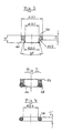
- the primary sealing of the system takes place via the gland-like seal 54, which is composed of a slide ring 56 made of carbon-reinforced PTFE and an elastomer O-ring 58.
- the sliding ring 56 is essentially rectangular in axial cross section and has a groove 60 on its one outer edge region, which is lower in the selected illustration, and which serves to receive the O-ring 58.
- the O-ring inserted into the groove 60 protrudes laterally and below over the corresponding boundary surfaces of the slide ring 56.
- the dimensions of the slide ring 56 and the O-ring 58 selected for the present case are given in mm in FIGS. 3 and 4.
- the sliding ring 56 has on its inside a radially inwardly extending, annular projection 64, specifically at the area opposite the groove 60.
- the projection is shown greatly exaggerated in Figure 2 for clarity. Because of the projection 64, there is essentially a line contact between the slide ring and the shift shaft, as a result of which the friction and wear are reduced.
- the seal 54 consisting of slide ring 56 and O-ring 58 is, as can be seen from FIG. 1, in the between the third annular sealing surface 24, the selector shaft 6, the third bore section 20 and the lower, radially extending, annular end face 62 of the cylindrical section 36 of the mounting plate 32 defined space used.
- the arrangement here is such that the O-ring 58 contacts the third annular sealing surface 24 and the third bore section 20, but not the selector shaft 6.
- the sliding ring 56 lies sealingly on the selector shaft 6, furthermore it lies on the end face 62, on the third bore section 20 and possibly on the third annular sealing surface 24.
- the O-ring 24 takes over the static sealing, while the sliding ring 56, which has excellent sliding properties, serves as a dynamic sealing element.
Landscapes
- Engineering & Computer Science (AREA)
- General Engineering & Computer Science (AREA)
- Mechanical Engineering (AREA)
- Sealing Devices (AREA)
Applications Claiming Priority (2)
| Application Number | Priority Date | Filing Date | Title |
|---|---|---|---|
| DE19893925888 DE3925888A1 (de) | 1989-08-04 | 1989-08-04 | Schaltwellenabdichtung bei armaturen |
| DE3925888 | 1989-08-04 |
Publications (2)
| Publication Number | Publication Date |
|---|---|
| EP0411652A1 true EP0411652A1 (fr) | 1991-02-06 |
| EP0411652B1 EP0411652B1 (fr) | 1994-01-26 |
Family
ID=6386553
Family Applications (1)
| Application Number | Title | Priority Date | Filing Date |
|---|---|---|---|
| EP19900114917 Expired - Lifetime EP0411652B1 (fr) | 1989-08-04 | 1990-08-03 | Etanchéité pour tige de vanne |
Country Status (2)
| Country | Link |
|---|---|
| EP (1) | EP0411652B1 (fr) |
| DE (1) | DE3925888A1 (fr) |
Cited By (2)
| Publication number | Priority date | Publication date | Assignee | Title |
|---|---|---|---|---|
| GB2287772A (en) * | 1994-03-10 | 1995-09-27 | Raymond George Coughlin | Gate valve stem sealing arrangement |
| EP0854993A4 (fr) * | 1995-10-17 | 1999-05-06 | Henry Valve Co | Ensemble de joint de tige pour robinets a tournant spherique |
Families Citing this family (2)
| Publication number | Priority date | Publication date | Assignee | Title |
|---|---|---|---|---|
| DE19710077A1 (de) * | 1997-03-12 | 1998-09-17 | Teg Mbh | Dichtung für drehbare Schaltwellen von Armaturen |
| DE202017105035U1 (de) | 2017-08-22 | 2018-11-23 | Samson Ag | Stellventil |
Citations (5)
| Publication number | Priority date | Publication date | Assignee | Title |
|---|---|---|---|---|
| BE550067A (fr) * | ||||
| GB958832A (en) * | 1959-07-22 | 1964-05-27 | Saunders Valve Co Ltd | Improvements in and relating to plug cocks |
| FR1469220A (fr) * | 1965-12-30 | 1967-02-10 | Thiault J | Vanne à boisseau sphérique |
| DE1299229B (de) * | 1967-01-18 | 1969-07-10 | Draegerwerk Ag | Absperrventil fuer Atemschutzgeraet |
| DE2700609A1 (de) * | 1977-01-08 | 1978-07-13 | Siegfried Ammann | Gleitdichtung fuer eine stangenfuehrung |
Family Cites Families (9)
| Publication number | Priority date | Publication date | Assignee | Title |
|---|---|---|---|---|
| DE8020410U1 (de) * | 1980-10-30 | Praedifa Praezisions-Dichtungs-Fabrik Gmbh, 7120 Bietigheim-Bissingen | Hydraulik-Stangen-Dichtsatz | |
| DE1141621B (de) * | 1959-07-08 | 1962-12-27 | Erwin Benz | Abdichtung von Ruehrwerkswellen in Druck- oder Unterdruckgefaessen |
| DE1982171U (de) * | 1967-03-21 | 1968-03-28 | Jakob Rusch Inhaber Willi Rusc | Schleifring-dichtung. |
| GB1425617A (en) * | 1972-06-12 | 1976-02-18 | Kitamura Valve Mfg Co L D | Fluid flow control valves |
| US3912221A (en) * | 1974-06-26 | 1975-10-14 | United States Pipe Foundry | Stem seal and retainer for gate valve |
| NL160645C (nl) * | 1975-12-25 | 1979-11-15 | Tlv Co Ltd | Afdichtconstructie voor een klepsteel van een afsluiter. |
| DE7815061U1 (de) * | 1978-05-19 | 1978-08-31 | Ing.-Buero Pfannenschmidt Gmbh, 2000 Hamburg | Schaltbare armatur |
| US4290497A (en) * | 1979-07-24 | 1981-09-22 | Eduardo Barnetche | Automatic wear compensating seal device |
| US4510960A (en) * | 1983-09-30 | 1985-04-16 | Fmc Corporation | Valve stem-to-bonnet backseat |
-
1989
- 1989-08-04 DE DE19893925888 patent/DE3925888A1/de active Granted
-
1990
- 1990-08-03 EP EP19900114917 patent/EP0411652B1/fr not_active Expired - Lifetime
Patent Citations (5)
| Publication number | Priority date | Publication date | Assignee | Title |
|---|---|---|---|---|
| BE550067A (fr) * | ||||
| GB958832A (en) * | 1959-07-22 | 1964-05-27 | Saunders Valve Co Ltd | Improvements in and relating to plug cocks |
| FR1469220A (fr) * | 1965-12-30 | 1967-02-10 | Thiault J | Vanne à boisseau sphérique |
| DE1299229B (de) * | 1967-01-18 | 1969-07-10 | Draegerwerk Ag | Absperrventil fuer Atemschutzgeraet |
| DE2700609A1 (de) * | 1977-01-08 | 1978-07-13 | Siegfried Ammann | Gleitdichtung fuer eine stangenfuehrung |
Cited By (2)
| Publication number | Priority date | Publication date | Assignee | Title |
|---|---|---|---|---|
| GB2287772A (en) * | 1994-03-10 | 1995-09-27 | Raymond George Coughlin | Gate valve stem sealing arrangement |
| EP0854993A4 (fr) * | 1995-10-17 | 1999-05-06 | Henry Valve Co | Ensemble de joint de tige pour robinets a tournant spherique |
Also Published As
| Publication number | Publication date |
|---|---|
| DE3925888A1 (de) | 1991-02-14 |
| DE3925888C2 (fr) | 1991-05-29 |
| EP0411652B1 (fr) | 1994-01-26 |
Similar Documents
| Publication | Publication Date | Title |
|---|---|---|
| EP0231302B1 (fr) | Dispositif obturateur sous forme de robinet a boisseau spherique | |
| DE2609446C3 (de) | Dichtring für einen Kugelhahn | |
| DE69216943T2 (de) | Drehbare Rohrverbindung mit verbesserter Dichtung | |
| EP0568950B1 (fr) | Vanne à roue cellulaire | |
| DE3877762T2 (de) | Gleitring-dichtung mit zentriermitteln. | |
| WO1998017934A1 (fr) | Coulisse, en particulier coulisse a pont tubulaire | |
| DE19932355A1 (de) | Drehdurchführung für wechselnde Medien | |
| DE1957309A1 (de) | Ventil fuer Vakuumleitungen | |
| DE4025832A1 (de) | Absperr- und regelklappe | |
| DE3003203C2 (de) | Dichtung für ein Absperrorgan für eine Fluidleitung | |
| EP0947749A2 (fr) | Robinet à tournant sphérique | |
| EP0780619A1 (fr) | Pièce enfichable | |
| DE4110080C2 (de) | Titel: Kugelhahn I | |
| EP0411652B1 (fr) | Etanchéité pour tige de vanne | |
| DE10342751A1 (de) | Dichtungsanordnung | |
| DD297690A5 (de) | Dichtungsanordnung | |
| DE4414243B4 (de) | Kugelhahn | |
| DE3727173A1 (de) | Durch ein kompressibles fluid, insbesondere pneumatisch schaltbare kupplungs- und bremsvorrichtung | |
| DE1775748C3 (de) | Dichtung für einen Kolbenschieber | |
| DE69522265T2 (de) | Stopfbuchse mit elastischer Montage der Dichtungen | |
| EP3385499A1 (fr) | Galet de coupe | |
| EP0560833B1 (fr) | Dispositif pour l'etancheification d'un interstice | |
| EP0463155B1 (fr) | Robinetterie d'arret avec un dispositif d'etancheite | |
| DE69210167T2 (de) | Dichtungsring für gleitende Teile, funktionierend bei sehr niedrigen Temperaturen | |
| DE2632397A1 (de) | Drehschieber mit drehbarem hahnkueken und gleitbeweglichen sitzen |
Legal Events
| Date | Code | Title | Description |
|---|---|---|---|
| PUAI | Public reference made under article 153(3) epc to a published international application that has entered the european phase |
Free format text: ORIGINAL CODE: 0009012 |
|
| AK | Designated contracting states |
Kind code of ref document: A1 Designated state(s): BE ES FR IT NL |
|
| 17P | Request for examination filed |
Effective date: 19910426 |
|
| 17Q | First examination report despatched |
Effective date: 19921009 |
|
| GRAA | (expected) grant |
Free format text: ORIGINAL CODE: 0009210 |
|
| AK | Designated contracting states |
Kind code of ref document: B1 Designated state(s): BE ES FR IT NL |
|
| PG25 | Lapsed in a contracting state [announced via postgrant information from national office to epo] |
Ref country code: IT Free format text: LAPSE BECAUSE OF FAILURE TO SUBMIT A TRANSLATION OF THE DESCRIPTION OR TO PAY THE FEE WITHIN THE PRESCRIBED TIME-LIMIT;WARNING: LAPSES OF ITALIAN PATENTS WITH EFFECTIVE DATE BEFORE 2007 MAY HAVE OCCURRED AT ANY TIME BEFORE 2007. THE CORRECT EFFECTIVE DATE MAY BE DIFFERENT FROM THE ONE RECORDED. Effective date: 19940126 Ref country code: ES Free format text: THE PATENT HAS BEEN ANNULLED BY A DECISION OF A NATIONAL AUTHORITY Effective date: 19940126 |
|
| ET | Fr: translation filed | ||
| PLBE | No opposition filed within time limit |
Free format text: ORIGINAL CODE: 0009261 |
|
| STAA | Information on the status of an ep patent application or granted ep patent |
Free format text: STATUS: NO OPPOSITION FILED WITHIN TIME LIMIT |
|
| 26N | No opposition filed | ||
| PGFP | Annual fee paid to national office [announced via postgrant information from national office to epo] |
Ref country code: FR Payment date: 19960716 Year of fee payment: 7 |
|
| PGFP | Annual fee paid to national office [announced via postgrant information from national office to epo] |
Ref country code: BE Payment date: 19960822 Year of fee payment: 7 |
|
| PGFP | Annual fee paid to national office [announced via postgrant information from national office to epo] |
Ref country code: NL Payment date: 19960828 Year of fee payment: 7 |
|
| PG25 | Lapsed in a contracting state [announced via postgrant information from national office to epo] |
Ref country code: BE Free format text: LAPSE BECAUSE OF NON-PAYMENT OF DUE FEES Effective date: 19970831 |
|
| BERE | Be: lapsed |
Owner name: CHEMAT G.M.B.H. ARMATUREN FUR INDUSTRIE- UND NUKL Effective date: 19970831 |
|
| PG25 | Lapsed in a contracting state [announced via postgrant information from national office to epo] |
Ref country code: NL Free format text: LAPSE BECAUSE OF NON-PAYMENT OF DUE FEES Effective date: 19980301 |
|
| PG25 | Lapsed in a contracting state [announced via postgrant information from national office to epo] |
Ref country code: FR Free format text: LAPSE BECAUSE OF NON-PAYMENT OF DUE FEES Effective date: 19980430 |
|
| NLV4 | Nl: lapsed or anulled due to non-payment of the annual fee |
Effective date: 19980301 |
|
| REG | Reference to a national code |
Ref country code: FR Ref legal event code: ST |