EP0411665A2 - Sichtanzeigegerät - Google Patents
Sichtanzeigegerät Download PDFInfo
- Publication number
- EP0411665A2 EP0411665A2 EP90114981A EP90114981A EP0411665A2 EP 0411665 A2 EP0411665 A2 EP 0411665A2 EP 90114981 A EP90114981 A EP 90114981A EP 90114981 A EP90114981 A EP 90114981A EP 0411665 A2 EP0411665 A2 EP 0411665A2
- Authority
- EP
- European Patent Office
- Prior art keywords
- brightness
- display
- fields
- indicators
- time
- Prior art date
- Legal status (The legal status is an assumption and is not a legal conclusion. Google has not performed a legal analysis and makes no representation as to the accuracy of the status listed.)
- Granted
Links
- 238000001514 detection method Methods 0.000 claims abstract description 27
- 125000004122 cyclic group Chemical group 0.000 claims description 3
- 238000005375 photometry Methods 0.000 description 16
- 238000000034 method Methods 0.000 description 9
- 230000008569 process Effects 0.000 description 4
- 230000004044 response Effects 0.000 description 4
- 238000005070 sampling Methods 0.000 description 4
- 239000003990 capacitor Substances 0.000 description 3
- 230000035945 sensitivity Effects 0.000 description 3
- 102100035233 Furin Human genes 0.000 description 2
- 101001022148 Homo sapiens Furin Proteins 0.000 description 2
- 101000701936 Homo sapiens Signal peptidase complex subunit 1 Proteins 0.000 description 2
- 101000661816 Homo sapiens Suppression of tumorigenicity 18 protein Proteins 0.000 description 2
- 238000005259 measurement Methods 0.000 description 2
- 230000000007 visual effect Effects 0.000 description 2
- 101710170230 Antimicrobial peptide 1 Proteins 0.000 description 1
- 102100036848 C-C motif chemokine 20 Human genes 0.000 description 1
- 102100035353 Cyclin-dependent kinase 2-associated protein 1 Human genes 0.000 description 1
- 101000713099 Homo sapiens C-C motif chemokine 20 Proteins 0.000 description 1
- 101000737813 Homo sapiens Cyclin-dependent kinase 2-associated protein 1 Proteins 0.000 description 1
- 101000911772 Homo sapiens Hsc70-interacting protein Proteins 0.000 description 1
- 101001139126 Homo sapiens Krueppel-like factor 6 Proteins 0.000 description 1
- 101001128694 Homo sapiens Neuroendocrine convertase 1 Proteins 0.000 description 1
- 101000828971 Homo sapiens Signal peptidase complex subunit 3 Proteins 0.000 description 1
- 101000585359 Homo sapiens Suppressor of tumorigenicity 20 protein Proteins 0.000 description 1
- 101000687727 Homo sapiens Transcriptional regulator PINT87aa Proteins 0.000 description 1
- 101000979222 Hydra vulgaris PC3-like endoprotease variant A Proteins 0.000 description 1
- 101000979221 Hydra vulgaris PC3-like endoprotease variant B Proteins 0.000 description 1
- 102100032132 Neuroendocrine convertase 1 Human genes 0.000 description 1
- 102100029860 Suppressor of tumorigenicity 20 protein Human genes 0.000 description 1
- 102100024797 Transcriptional regulator PINT87aa Human genes 0.000 description 1
- 230000003213 activating effect Effects 0.000 description 1
- 230000008859 change Effects 0.000 description 1
- 238000006243 chemical reaction Methods 0.000 description 1
- 230000001276 controlling effect Effects 0.000 description 1
- 230000003247 decreasing effect Effects 0.000 description 1
- 230000003111 delayed effect Effects 0.000 description 1
- 238000010586 diagram Methods 0.000 description 1
- 239000006185 dispersion Substances 0.000 description 1
- 230000004438 eyesight Effects 0.000 description 1
- 230000006870 function Effects 0.000 description 1
- 238000003780 insertion Methods 0.000 description 1
- 230000037431 insertion Effects 0.000 description 1
- 108090000237 interleukin-24 Proteins 0.000 description 1
- 230000007246 mechanism Effects 0.000 description 1
- 230000001105 regulatory effect Effects 0.000 description 1
- HODRFAVLXIFVTR-RKDXNWHRSA-N tevenel Chemical compound NS(=O)(=O)C1=CC=C([C@@H](O)[C@@H](CO)NC(=O)C(Cl)Cl)C=C1 HODRFAVLXIFVTR-RKDXNWHRSA-N 0.000 description 1
Images




Classifications
-
- G—PHYSICS
- G03—PHOTOGRAPHY; CINEMATOGRAPHY; ANALOGOUS TECHNIQUES USING WAVES OTHER THAN OPTICAL WAVES; ELECTROGRAPHY; HOLOGRAPHY
- G03B—APPARATUS OR ARRANGEMENTS FOR TAKING PHOTOGRAPHS OR FOR PROJECTING OR VIEWING THEM; APPARATUS OR ARRANGEMENTS EMPLOYING ANALOGOUS TECHNIQUES USING WAVES OTHER THAN OPTICAL WAVES; ACCESSORIES THEREFOR
- G03B17/00—Details of cameras or camera bodies; Accessories therefor
- G03B17/18—Signals indicating condition of a camera member or suitability of light
- G03B17/20—Signals indicating condition of a camera member or suitability of light visible in viewfinder
Definitions
- the present invention generally relates to a display device which is overlaid on the picture in the viewfinder of the camera.
- One aspect of the present invention is the possibility to choose whether or not to have an superimposed indication within the frame and if the indication is chosen, the brightness in compliance with the numeric information will track the brightness of the object to ensure utmost visual comfort.
- Another aspect of this invention is the automatic variation of the brightness of the information in response to that of the object. Since this is made possible through a phased combination of a constant-current drive and a brightness modulation drive, photometric error under low brightness due to delayed response of the photometric sensor is prevented.
- the explanatory Figure 1A shows a camera seen from the side.
- the reference numeral 1 denotes a mount, 2a a main mirror, 2b a sub-mirror, 3 a film surface, 4 a LED flood light prism, 5 a focusing frame, 6 a device for displaying information outside the frame reticle in the viewfinder, 7 a pentaprism, 8 a photometric lens for the SPC photometric sensor, and 9 an eyepiece of the viewfinder, and 10 a sensor for autofocusing.
- the light passing through the objective (not shown in the figure) is deflected 90° by the main mirror 2a and reflected by the pentaprism 7 and reaches the eye after passing through the eyepiece 9.
- the light reflected by the sub-mirror 2b is directed to the autofocusing sensor 10.
- the light reaching the matter field of the focusing frame 5 is projected onto the SPC photometric sensor via the photometric lens.
- the LED light passes through the flood light prism 4 and is reflected by the main-mirror.
- the light is deflected vertically by the microprism array on the indicator portion of the focusing frame 5 and travels through the pentaprism 7 to reach the eye via the eyepiece.
- indications like the information generated by the display device 6, have been shown outside the frame reticle device and could not get lost in the viewfinder image. Selecting a reasonable brightness once for all was enough. However, to track the brightness of the object when superimposing, it is necessary to change the brightness of the indicators to follow the camera's 20-step dynamic photometric range.
- the three fields Z1 to Z3, shown in Figure 2 indicate the photometric fields of the SPC photometric sensor. These fields, including the superimpose indicators D1 through D3, can be distilled as necessary.
- FIG. 3 shows the circuit that actualizes the present embodiment.
- the photometric sensors SPC1 to SPC3 correspond with the fields Z1 to Z3.
- Each sensor is connected with photometric amplifiers AMP1 to AMP3 and condenser diodes DI1 to DI3 to thereby transform the light into electric impulses and the logarithmical compressed voltage is transmitted to the inputs IN1 to IN3 of the MPX multiplexers.
- CPU central processing unit
- ROM where the programs are stored in
- RAM contains the random access memory concerning the work area for arithmetic functions
- EEPROM is a non-volatile storage for storing non-volatile memory like data concerning adjustments
- PIO is general-use input and output port
- TIMER which is a timer/counter.
- the LEDs corresponding to the superimpose indicators D1 to D3 are called LED1 to LED2 and each has three constant current sources I i1 to I i3 (I corresponds to LED1 to LED3). These constant current sources are constructed in a way so that when the register REG's output Bij is HIGH they are in 'enable' state. When LOW, they are in 'disable' state.
- the photometric circuit wil be described with reference to Figure 4.
- the condenser diode DI1 contains a condenser Cd1.
- the brightness of the superimpose indicators must be adjusted to track the brightness of the subject in the viewfinder in order to obtain an image easily observed with the eye.
- the brightness of the object processed by the camera is divided into a maximum of 20 different levels. When brightness modulation is used to maintain such a wide dynamic range, problems like that indicated in (a) may appear.
- a large current should be used to allow observation under high brightness conditions.
- the LED should light for a short time and duty should be shortened to thereby suppress the brightness observed by the human eye.
- the output of the SPC1 photometric sensor in the form of the photo-electric current ISPC1 is greatly increased when the LED lights. Accordingly, the electric charge is sufficient to charge the capacitor C1 and the current is quickly returned to a balanced state.
- the photo-electric current ISPC1 depending upon the brightness of the subject, used to discharge the charged capacitor C1 has not yet reached a balanced state at the time 't'.
- (b) shows the drive when a low electric current and long lighting tme is applied and (a), that will appear to be the same as (b) when observed by the human eye, shows the drive when a high electric current and short lighting time is applied.
- the photo-electric current ISPC1 does not increase so much according to the lighting of the LED and the charge of the capacitor C1 also requires time. Since the potential difference of the voltage V1 between a lighted state and un-lighted state is small, it is possible for the current to reach a balanced state at the 't' time instant.
- the photometric sensor When superimposing, the photometric sensor measures the object. Since the superimpose indicators appear within the sensitivity distribution, the light intensity is increased by the presence of the indicators. Accordingly, if photometry is carried out while the indicators are displayed, the measured output will consist of wrong data. A time sharing process is therefore indispensable.
- T wait span of waiting time that allows the voltage at the photometric circuit to settle down to a level that corresponds to the voltage for the brightness of the object.
- An ample wait-time may be secured in addition to a T wait span by having this display luminance modulation successive to the previous sequence, eliminating any intervening gap.
- Figure 5 is a graphic presentation of the relationships among the superimpose display corresponding to the object brightness, the drive current and the drive time, with the horizontal bar showing by logarithm the object brightness on the PINT plate 5, and the vertical bar showing the LED-lit time T x , and the drive current of the superimpose display at a phase shown at Figure 6.
- a strong drive current is applied when the object is very bright like line one, and the drive current should be decreased as the object brightness goes down.
- Figure 7 shows the currents and the drive-time lengths, T x , corresponding respectively to point a through point f, with the vertical line length representing the current and the horizontal "on" span T x .
- the ratio of line one to line two may be one to eight
- the drive time ratio of line one to line two at which the human eye perceives the object to be at the same brightness the drive time ratio still does not agree to one eights, resulting from the unlinear relationship between the current and the beam quantity.
- ⁇ j is recommendably 0.4 - 0.8, depending on LED.
- Points g and c refer to where the humen eye perceives as the same brightness.
- simple application of modulation factors like L1, L2, L3 and ⁇ 1, ⁇ 2, ⁇ 3 to the equation shown above allows superimpose operation that is free of undesirable influences from such as the human eye characteristics, LED characteristics, constant current fluctuations, dispersion in LED beam projection, etc.
- combined use of duty-drive and gradual-constant-current drive provides for superimpose coverage over a wide and dynamic range.
- Figure 8 represents the followings: ST01: The photometry, computation and display are performed as the main routine operation. In addition, timered insertion is also available when it carries timewise compatibility as well as simultaneous operation of another program.
- ST02 Calling of the photometric routine.
- N represents the input factor, that is, the number of the photometric sampling; and AD(i),1-3 stands for the object brightness within the sensitivities of the three sensors.
- the measured value AD(i) of each sensor is taken from the mean value of several sampling within the T measure time span.
- the output variables, 'x' determine the brightness of the flashing LEDs on the focus panel 5.
- ST04 The brightness information 'x' on the focus panel is the input power, and the electrical current plus the duty drive time T x are the output power.
- the method shown in Figure 5 is algorithmic in principle.
- ST05 A Display Driven Routine is called.
- ST06 Wait for 'T wait ' is necessary for safe photometry. Then, it will go back to the photometric routine - call mode.
- ST11 Photometric routine.
- ST13 to 15 To get the average value of 'N' times of three sensors, the value of SUM (i) 1 to 3 should be temporary cleared.
- ST18 To do the photometry of the 'i' th number of sensor IN i should be selected by transmitting the output power to a port of multiplexer.
- ST19 Do a A/D conversion through the A/D converter and make that value "D”.
- ST21 Wait for 'T LOOP ' which have been obtained from ST 12.
- AD (i) tells that the average photometry value 'N' times, of each correponding sensor, will be inputted to each 'AD (i)'. Namely, it means that the brightness of the object on focus panel 5, when the LED is off, which has been inputted into AD (i), was correspondingly determined by each sensor.
- ST27 Return to Main Routine.
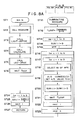
- ST53 to ST60 Formulate 'j' and 'T x ' as follows to clarify the relation of 'x' and L1, L2, L3 in Figure 5. The above calculation has been obtained from ST53 to ST60.
- Current 1 to 3 corresponds to the constant electrical currents of lines 1 to 3 in Figure 5 respectively.
- ST61 Return to Main Routine.
- ST72 to ST76 Set the output of B ij of register REG while watching the (i) value of the expected lighting LEDs. For example, when LED 1 is driven by the constant electrical current source 2 (line 2), the constant electrical current I12 will be turned on by setting B12 high, and LED 1 will be driven by the electrical current corresponding to line 2.
- ST77 Wait for lighting time T x .
- ST83 Wait for 'T a - T x ' time.
- ST84 Return to Main Routine. Ideally, delay time due to execution of program should be taken into consideration when setting the wait time. However, in order to be practical, we have excluded the factor for simplicity sake, and because the value of it is small enough to discard.
- ST90 Auto-focus Routine This auto-focus routine is the program which has been drawn from the Main routine mode. It has three measuring areas which have been set up almost in the same way as the superimpose area of d1 - d3 shown in Figure 1. This will be achieved by setting up the position of sensor 10 for focus and for photometry.
- St91 Select the mode for auto-focus. Auto-focus will be possible by three area measurements. There is a manual-mode in which the photographer can select a certain measuring area, and auto-focus mode where 3 sets of sensors measure an adequate amount of area automatically.
- ST92 It judges, when the auto-focus mode is selected, where the main subject is located within the three measuring areas. For example, it judges that the nearest object is the main subject and achieves automatic focusing by the output of the particular sensor for that area.
- ST93 When the manual mode is selected, activate the superimpose display (one of d1, d2 or d3) which corresponds to an area selected among the three measuring areas.
- the command when the auto-mode is selected to flash the superimposition of d1 to d3 which corresponds to the measuring areas on the focus lens.
- the number of indicated superimposition d1 to d3 is not necessarily one.
- ST94 Return In the present embodiment, the photometric fields of the SPC photometry sensor corresponding to the superimpose indicators are slightly larger than the indicators, but one indicator corresponds to one sensor. However, sometimes one indicator area may stretch over the photometric fields of several SPC photometry sensors. In this case, the average of the outputs of the involved sensors is output and used to control the brightness to obtain an optimum display.
- the operation is based on the average value of the logarithmical compressed photometric values in the case of this embodiment, but by giving priority to bright sensor outputs and then basing the operation on the average output, an even more appropriate brightness of the superimpose indicators is maintainable.
- the superimpose indicators are displayed at several locations, when selecting one indicator among several to be displayed, this indicator will have a brightness corresponding to the brightness of the corresponding field of the object. If more than 2 indicators are selected to be displayed, the brightness of the display will be determined by the average output determined by the brightness intensity of the fields corresponding to the indicators. In this way it is possible to obtain an optimum display of the indications superimposed on the object inside the frame reticle of the viewfinder.
- the superimpose indicators will neither be too light nor too dark, but will keep track with the brightness of the object. At the same time it is possible to obtain a camera display device that is also capable of maintaining balance of brightness between several superimpose indicators.
- the light state, wait state and display state in a cyclic order it is possible to control the brightness of the display so the brightness in near real-time follows the brightness of the object. In addition, it is possible to prevent bad influences upon the photometry.
- the amount of stray light is kept to a minimum especially in the case of low brightness conditions. Accordingly, the slowness of the response speed of the photometer sensor in the case of low brightness conditions. Accordingly, the slowness of the response speed of the photometer sensor in the case of low brightness conditions is effective in preventing erroneous light measuring.
- the brightness of the superimpose indicators is maintained by a simple brightness modulation method, it is possible to offer a visually comfortable display that is always easily discernible. Since individual eyesights vary greatly, the control of the display is systemized, opeing up for simplified process adjustment. The improved capacity of the memory, where the data concerning adjustments is stored, also contributes to minimizing the adjustment variables.
- a superimposing display device that superimposes indicators upon the image seen in the viewfinder are provided a display means that displays multiple displays in fields superimposed upon said image of said viewfinder, a detection means that detects the brightness intensity of said fields, and a control means that controls the brightness of said displays, said control means controlling the brightness intensity information concerning a field obtained by the detection means.
- the superimpose indicators are displayed at several locations and by application of both a phased constant drive and brightness modulation, thereby enabling to display superimposed indicators with a wide dynamic range capable of keeping track of an object possessing a brightness pattern.
Landscapes
- Physics & Mathematics (AREA)
- General Physics & Mathematics (AREA)
- Indication In Cameras, And Counting Of Exposures (AREA)
- Viewfinders (AREA)
Applications Claiming Priority (6)
| Application Number | Priority Date | Filing Date | Title |
|---|---|---|---|
| JP20305889A JPH0365938A (ja) | 1989-08-04 | 1989-08-04 | カメラの表示装置 |
| JP203060/89 | 1989-08-04 | ||
| JP20306189A JPH0365940A (ja) | 1989-08-04 | 1989-08-04 | カメラの表示装置 |
| JP203061/89 | 1989-08-04 | ||
| JP20306089A JPH0365939A (ja) | 1989-08-04 | 1989-08-04 | カメラの表示装置 |
| JP203058/89 | 1989-08-04 |
Publications (3)
| Publication Number | Publication Date |
|---|---|
| EP0411665A2 true EP0411665A2 (de) | 1991-02-06 |
| EP0411665A3 EP0411665A3 (en) | 1991-05-15 |
| EP0411665B1 EP0411665B1 (de) | 1995-12-20 |
Family
ID=27328183
Family Applications (1)
| Application Number | Title | Priority Date | Filing Date |
|---|---|---|---|
| EP90114981A Expired - Lifetime EP0411665B1 (de) | 1989-08-04 | 1990-08-03 | Sichtanzeigegerät |
Country Status (3)
| Country | Link |
|---|---|
| US (1) | US5404193A (de) |
| EP (1) | EP0411665B1 (de) |
| DE (1) | DE69024277T2 (de) |
Families Citing this family (6)
| Publication number | Priority date | Publication date | Assignee | Title |
|---|---|---|---|---|
| JPH07159862A (ja) * | 1993-12-02 | 1995-06-23 | Nikon Corp | カメラのファインダー |
| JPH07248523A (ja) * | 1994-03-11 | 1995-09-26 | Nikon Corp | 測光値補正装置付きカメラ |
| JPH07333060A (ja) * | 1994-06-07 | 1995-12-22 | Nikon Corp | 測光装置 |
| JPH08110564A (ja) * | 1994-10-13 | 1996-04-30 | Canon Inc | ファインダ表示装置を有する光学機器 |
| US5784656A (en) * | 1994-12-05 | 1998-07-21 | Nikon Corporation | Camera with light dividing devices |
| US6411306B1 (en) | 1997-11-14 | 2002-06-25 | Eastman Kodak Company | Automatic luminance and contrast adustment for display device |
Family Cites Families (12)
| Publication number | Priority date | Publication date | Assignee | Title |
|---|---|---|---|---|
| JPS6226021B2 (de) * | 1973-07-28 | 1987-06-05 | Oki Denki Kogyo Kk | |
| JPS6029931B2 (ja) * | 1976-02-25 | 1985-07-13 | 株式会社日立製作所 | 表示装置制御回路 |
| JPS57161708A (en) * | 1981-03-28 | 1982-10-05 | Olympus Optical Co Ltd | Focusing detector having variable visual field of detection |
| JPS57177134A (en) * | 1981-04-24 | 1982-10-30 | Fuji Photo Optical Co Ltd | Indicator placed in finder |
| JPS57196221A (en) * | 1981-05-28 | 1982-12-02 | Asahi Optical Co Ltd | Warning display mechanism for photographic information of camera |
| JPH0625844B2 (ja) * | 1983-05-26 | 1994-04-06 | キヤノン株式会社 | カメラ |
| JPS6083995A (ja) * | 1983-10-14 | 1985-05-13 | キヤノン株式会社 | 輝度変調回路 |
| US4746947A (en) * | 1985-02-25 | 1988-05-24 | Minolta Camera Kabushiki Kaisha | Exposure calculating device |
| US4792820A (en) * | 1985-09-13 | 1988-12-20 | Minolta Camera Kabushiki Kaisha | Camera with automatic focus and exposure control means |
| US4754296A (en) * | 1985-11-21 | 1988-06-28 | Polaroid Corporation | Method of and apparatus for displaying alphanumeric range in camera viewfinder |
| JPH0621912B2 (ja) * | 1987-01-14 | 1994-03-23 | キヤノン株式会社 | カメラ |
| JPH0250115A (ja) * | 1988-08-11 | 1990-02-20 | Minolta Camera Co Ltd | 焦点検出用光学装置 |
-
1990
- 1990-08-03 EP EP90114981A patent/EP0411665B1/de not_active Expired - Lifetime
- 1990-08-03 DE DE69024277T patent/DE69024277T2/de not_active Expired - Fee Related
-
1993
- 1993-02-22 US US08/020,454 patent/US5404193A/en not_active Expired - Lifetime
Also Published As
| Publication number | Publication date |
|---|---|
| EP0411665B1 (de) | 1995-12-20 |
| DE69024277D1 (de) | 1996-02-01 |
| EP0411665A3 (en) | 1991-05-15 |
| DE69024277T2 (de) | 1996-06-27 |
| US5404193A (en) | 1995-04-04 |
Similar Documents
| Publication | Publication Date | Title |
|---|---|---|
| US6670992B2 (en) | Camera having light measuring device operable based on focus detecting device | |
| US6151073A (en) | Intelligent camera flash system | |
| EP0441303B1 (de) | Kamera mit Display im Bereich des Suchers | |
| US6463214B1 (en) | Multi-point autofocus system | |
| DE4330265A1 (de) | Optisches Gerät mit einer Einrichtung zum Erfassen einer Sehachsenrichtung | |
| US5255044A (en) | Automatic exposure control apparatus with improved exposure value calculation for photographing a moving object | |
| US5424788A (en) | Slit lamp microscope | |
| EP0411665B1 (de) | Sichtanzeigegerät | |
| US6240252B1 (en) | Camera | |
| DE69736885T2 (de) | Kamera mit einer Scharfeinstellungsvorrichtung | |
| DE69628492T2 (de) | Anordnung mit Vorrichtung zum Bestimmen der Blichrichtung | |
| US5189460A (en) | Camera detecting luminance from a plurality of areas | |
| US5041859A (en) | Automatic focusing detection device for cameras | |
| DE4328277A1 (de) | Optisches Gerät mit Sehachsendaten-Eingabefunktion | |
| US4365880A (en) | Indicator for camera | |
| JP3890098B2 (ja) | 光学装置 | |
| EP0578174B1 (de) | Photometer mit einem verstellbaren dynamischen Bereich für einen Photoapparat | |
| JP3912853B2 (ja) | カメラ | |
| JPH03140930A (ja) | 一眼レフレックスカメラのファインダー内表示装置 | |
| JP4086367B2 (ja) | カメラ | |
| JPH10186443A (ja) | カメラ | |
| US6327435B1 (en) | Focus adjusting apparatus | |
| JPH0365939A (ja) | カメラの表示装置 | |
| DE4205350A1 (de) | Kamera mit blickpunktmesseinrichtung | |
| JPH0365940A (ja) | カメラの表示装置 |
Legal Events
| Date | Code | Title | Description |
|---|---|---|---|
| PUAI | Public reference made under article 153(3) epc to a published international application that has entered the european phase |
Free format text: ORIGINAL CODE: 0009012 |
|
| AK | Designated contracting states |
Kind code of ref document: A2 Designated state(s): DE FR GB |
|
| 17P | Request for examination filed |
Effective date: 19901221 |
|
| PUAL | Search report despatched |
Free format text: ORIGINAL CODE: 0009013 |
|
| AK | Designated contracting states |
Kind code of ref document: A3 Designated state(s): DE FR GB |
|
| 17Q | First examination report despatched |
Effective date: 19930503 |
|
| GRAA | (expected) grant |
Free format text: ORIGINAL CODE: 0009210 |
|
| AK | Designated contracting states |
Kind code of ref document: B1 Designated state(s): DE FR GB |
|
| REF | Corresponds to: |
Ref document number: 69024277 Country of ref document: DE Date of ref document: 19960201 |
|
| ET | Fr: translation filed | ||
| PLBE | No opposition filed within time limit |
Free format text: ORIGINAL CODE: 0009261 |
|
| STAA | Information on the status of an ep patent application or granted ep patent |
Free format text: STATUS: NO OPPOSITION FILED WITHIN TIME LIMIT |
|
| 26N | No opposition filed | ||
| REG | Reference to a national code |
Ref country code: GB Ref legal event code: IF02 |
|
| PGFP | Annual fee paid to national office [announced via postgrant information from national office to epo] |
Ref country code: DE Payment date: 20080831 Year of fee payment: 19 |
|
| PGFP | Annual fee paid to national office [announced via postgrant information from national office to epo] |
Ref country code: FR Payment date: 20080821 Year of fee payment: 19 |
|
| PGFP | Annual fee paid to national office [announced via postgrant information from national office to epo] |
Ref country code: GB Payment date: 20080814 Year of fee payment: 19 |
|
| GBPC | Gb: european patent ceased through non-payment of renewal fee |
Effective date: 20090803 |
|
| REG | Reference to a national code |
Ref country code: FR Ref legal event code: ST Effective date: 20100430 |
|
| PG25 | Lapsed in a contracting state [announced via postgrant information from national office to epo] |
Ref country code: FR Free format text: LAPSE BECAUSE OF NON-PAYMENT OF DUE FEES Effective date: 20090831 Ref country code: DE Free format text: LAPSE BECAUSE OF NON-PAYMENT OF DUE FEES Effective date: 20100302 |
|
| PG25 | Lapsed in a contracting state [announced via postgrant information from national office to epo] |
Ref country code: GB Free format text: LAPSE BECAUSE OF NON-PAYMENT OF DUE FEES Effective date: 20090803 |