EP0412315A2 - Amortisseur de son - Google Patents
Amortisseur de son Download PDFInfo
- Publication number
- EP0412315A2 EP0412315A2 EP90113501A EP90113501A EP0412315A2 EP 0412315 A2 EP0412315 A2 EP 0412315A2 EP 90113501 A EP90113501 A EP 90113501A EP 90113501 A EP90113501 A EP 90113501A EP 0412315 A2 EP0412315 A2 EP 0412315A2
- Authority
- EP
- European Patent Office
- Prior art keywords
- sound
- hollow body
- air
- wall
- duct
- Prior art date
- Legal status (The legal status is an assumption and is not a legal conclusion. Google has not performed a legal analysis and makes no representation as to the accuracy of the status listed.)
- Granted
Links
Images


Classifications
-
- F—MECHANICAL ENGINEERING; LIGHTING; HEATING; WEAPONS; BLASTING
- F04—POSITIVE - DISPLACEMENT MACHINES FOR LIQUIDS; PUMPS FOR LIQUIDS OR ELASTIC FLUIDS
- F04D—NON-POSITIVE-DISPLACEMENT PUMPS
- F04D29/00—Details, component parts, or accessories
- F04D29/66—Combating cavitation, whirls, noise, vibration or the like; Balancing
-
- G—PHYSICS
- G10—MUSICAL INSTRUMENTS; ACOUSTICS
- G10K—SOUND-PRODUCING DEVICES; METHODS OR DEVICES FOR PROTECTING AGAINST, OR FOR DAMPING, NOISE OR OTHER ACOUSTIC WAVES IN GENERAL; ACOUSTICS NOT OTHERWISE PROVIDED FOR
- G10K11/00—Methods or devices for transmitting, conducting or directing sound in general; Methods or devices for protecting against, or for damping, noise or other acoustic waves in general
- G10K11/16—Methods or devices for protecting against, or for damping, noise or other acoustic waves in general
Definitions
- This invention relates to a sound attenuator provided in an air passage for weakening the noise generated by a blower, air conditioner, or the like, and including a special porous structure.
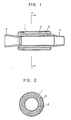
- FIGURES 1 and 2 A known sound attenuator of the type to which this invention pertains is shown by way of example in FIGURES 1 and 2. It is the device which is disclosed in Japanese Utility Model Publication No. 33898/1985 and intended for use in a vacuum cleaner. It comprises a cylindrical duct 1, an inner cylinder 2 formed from a nonwoven fabric and having a wall thickness of 0.1 to several millimeters, and a sound-absorbing material 3, such as felt or glass wool, filling the annular space between the duct 1 and the inner cylinder 2. The inner cylinder 2 and the sound-absorbing material 3 cooperate to define a sound absorber. The device is fitted by connectors 4 in an appropriate portion of the air passage of the cleaner. The inner cylinder 2 has a smooth inner surface formed by treatment with heat or a resin.
- the sound-absorbing material 3 having an indefinite shape is held by and between the duct 1 and the inner cylinder 2 formed from the nonwoven fabric transmitting a sound wave therethrough, and the inner cylinder 2 has a smoothed inner surface to prevent any fluffing that would otherwise be unavoidable as a drawback of the nonwoven fabric and result in the gathering of dust or dirt by its inner surface, leading eventually to the blocking of the air passage.
- the known device has, however, a number of drawbacks, too. It comprises as many as three components, i.e., the duct 1, the inner cylinder 2 and the sound-absorbing material 3. Its fabrication calls for a fairly complicated process including the step of forming a smooth inner surface on the inner cylinder 2 and the step of incorporating the sound-absorbing material 3 having an indefinite shape. Therefore, the device is considerably expensive to manufacture and yet there is no assurance of all of the products being always of the same reliable quality.
- the sound-absorbing material 3 has a substantially uniform specific density throughout it. As it has an indefinite shape, it is difficult to dispose in a way giving it the optimum specific gravity distribution enabling it to exhibit good sound-absorbing property, or form into a body having a complicated shape.
- flanking transmission Another drawback of the known device is due to the phenomenon called flanking transmission.
- the device can be prolonged to achieve a higher rate of attenuation, its prolongation beyond a certain limit brings about a sharp drop in its attenuation rate per unit length, since the noise caused by the propagation of vibration through the sound-absorbing material 3 becomes predominant and is transmitted to the exit of the device without being substantially attenuated.
- This phenomenon is discussed in detail by William F. Kerka in his paper entitled “Attenuation of Sound in Lined Ducts With and Without Air Flow", ASHRAE JOURNAL, March 1963.
- a sound attenuator which includes a sound absorber having a simple constructin and retaining a desired shape, while exhibiting good sound absorbing property even in a relatively low frequency range, which is inexpensive to manufacture, and which can always be reproduced without changing in quality.
- a sound attenuator comprising a sound absorber which includes: a first porous structure of a hard material, composed of a hollow porous body as an attenuator air passage therethrough, and a plurality of projections formed integrally on the outer wall surface of the porous body, the porous structure being disposed in a duct coaxially therewith; and an outer layer of air formed between the outer wall surface of the porous body and the inner wall surface of the duct between which the projections serve as spacers.
- the projections may include at least one projection extending about the whole circumference of the porous body and having a shape which is substantially identical to the cross-sectional shape of the air layer as taken at right angles to the longitudinal axis of the air passage.
- the attenuator may further comprise a second porous structure of a hard material which comprises a hollow cylindrical porous body positioned coaxially with the duct and having at least one end closed by a generally semispherical or conical air guide cover.
- a sound attenuator of the splitter type for use in a rectangular duct having a cross section divided into a plurality of portions along its width or height, which comprises at least one each sound absorber disposed respectively to those portions, is composed of a hollow porous structure of a hard material, an inner layer of air therein whose each end is closed by a generally semicircular or triangular air guide cover forming an integral part of the porous structure.
- the porous structure is preferably provided with at least a pair of linear projections lying at right angles to the longitudinal axis of an attenuator air passage, and each formed integrally on one of the opposite inner wall surfaces of the porous structure.
- the sound absorber includes the hollow porous structure having a porous wall and the outer or inner layer of air, it exhibits good sound-absorbing property even in a relatively low frequency range, even if it may have a small wall thickness.
- the porous structure of a hard material, the projections and semicircular or otherwise shaped covers formed integrally as an integral part maintain the outer or inner layer of air in definite dimensions as desired. Therefore, the device of this invention can be manufactured at a very low cost and can always be reproduced without changing in quality, e.g., dimensions and sound-absorbing property.
- linear projections as hereinabove described enable the attenuation of the noise caused by the propagation of vibration along the porous structure and thereby ensure that the device achieve a satisfactorily high rate of attenuation per unit length, even if it may be considerably long.
- the device exhibits a still better sound-absorbing performance if the porous body has a specific gravity varying continuously along its wall thickness or plane. Its performance in a low frequency range can still be improved if the porous body is provided with a skin layer having a thickness not exceeding 100 microns on its wall surface facing the air passage.
- FIGURES 3 and 4 A sound attenuator embodying this invention is shown in FIGURES 3 and 4, and includes a duct 1 and connectors 4 which are basically identical to their counterparts in the known device as hereinbefore described.
- a salient feature of the device according to this invention resides in a hollow porous structure 5 formed from a hard, but porous material.
- the porous structure 5 comprises a hollow cylindrical porous body 5 a disposed in the duct 1 coaxially therewith and defining an attenuator air passage 6 therethrough.
- the porous body 5 a is provided on its outer peripheral surface with a plurality of radially outwardly extending projections 5 b each forming an integral part of the porous body 5 a .
- the projections 5 b serve as spacers for holding the porous body 5 a in an appropriately spaced apart relation from the inner wall surface of the duct 1 and thereby maintaining an outer air layer 7 between the outer wall surface of the porous body 5 a and the inner wall surface of the duct 1.
- the projections 5 b include one circumferentially extending projection 5 c which extends about the whole circumference of the porous body 5 a in the mid-portion of the duct 1 and has a shape which is substantially equal to the cross-sectional shape of the air layer 7 as taken at right angles to the longitudinal axis of the air passage 6.
- the porous body 5 a and the air layer 7 define a sound absorber.
- the sound absorber therefore, exhibits good sound-absorbing property even in a relatively low frequency range, even if the porous body 5 a may have a relatively small wall thickness.
- the porous body 5 a formed from a hard material and the projections 5 b and 5 c of the same material maintain the air layer 7 in accurate and definite dimensions. Therefore, the device of this invention can be manufactured at a very low cost and can, moreover, be reproduced at any time without changing in quality, e.g., dimensions and sound-absorbing property.
- FIGURE 5 shows the results of a series of experiments which were conducted to compare the attenuation rates of devices each having a circumferential projection and devices not having any circumferential projection.
- each of the two groups had a different length from one another, and each device of one group was of the same length with one device of the other group.
- the circumferential projection manifested its effect in every device having a length of about 1 m or more and added as much as a maximum of about 8 dB to the result of attenuation by any device having no circumferential projection, as is obvious from FIGURE 5.
- FIGURE 6 showing a device according to another embodiment of this invention.
- the device is particularly intended for use in a duct 1 having a large diameter. It includes a first hollow porous structure 5 which is substantially identical to the structure 5 shown in FIGURES 3 and 4, and a second hollow porous structure 8 formed from a hard porous material and disposed in the first porous structure 5 coaxially with it and the duct 1.
- the second porous structure 8 is provided for making up any insufficiency of the attenuation which can be achieved by the device of FIGURES 3 and 4 having only a sound absorber located along the inner wall surface of the duct 1.
- the structure 8 comprises a hollow cylindrical porous body 8 a having one end closed by an air guide cover 8 b forming an integral part of the porous body 8 a .
- the cover 8 b has a generally semispherical or conical shape and is provided at that end of the porous body 8 a which is located at the upstream end of the device, for allowing air to flow smoothly into an attenuator air passage 6.
- the second porous structure 8 is so sized as to reduce the cross-sectional area of the air passage 6 to about a half, and thereby makes it possible to achieve an about twice higher rate of attenuation.
- the structure 8 defines an inner air layer 7 therein, while the first porous structure 5 defines an outer air layer 7.
- the structure 8 is also formed from a hard material and has a small wall thickness. Therefore, the device as a whole can be manufactured at a very low cost and can always be reproduced without changing in quality, e.g., dimensions and sound-absorbing property.
- the second porous structure 8 is connected to the first porous structure 5 by a plurality of connecting legs 9 and is thereby held coaxially with the duct 1.
- Each leg 9 can be formed as an integral part of both of the structures 5 and 8 as shown in FIGURE 6, though it may alternatively be formed as a separate part from one or both of the structures 5 and 8.
- FIGURES 3 and 4 and FIGURE 6 are used in a round duct 1, it is needless to say that the device of this invention is equally effective when used with a differently shaped duct, such as one having a square, rectangular or oval cross section.
- the circumferential projection 5 c has been shown as having an outside diameter which is equal to the inside diameter of the duct 1, no particular problem arises from any circumferential projection having except at a plurality of edge portions an outside diameter which is slightly smaller than the inside diameter of the duct 1, so that the porous structure 5 may be easier to insert into the duct 1.
- FIGURE 7 showing a splitter type device according to still another embodiment of this invention.
- the device is particularly suitable for use in a duct 1 having a considerably large cross-sectional area.
- the duct 1 has a rectangular cross section which is divided into a plurality of portions along its width or height.
- Each cross-sectional portion of the duct 1 is provided with a sound absorber.
- the sound absorber is defined by a hollow porous structure 10 formed from a hard porous material and comprising a hollow porous body 10 a defining an inner air layer 7 therein.
- the porous body 10 a has each end closed by an air guide cover 10 b having a generally semicircular or triangular shape.
- the covers 10 b enable a smooth flow of air at both ends of an attenuator air passage 6 and also hold the porous body 10 a and the inner air layer 7 in proper shape.
- Each porous body 10 a is provided with a pair of integrally formed linear projections 10 c on the opposite inner wall surfaces thereof, respectively.
- the projections 10 c lie at right angles to the direction of air flow through the air passage 6 and contribute to reducing the flanking transmission of noise along the porous body 10 a .
- the device of FIGURE 7 also can be manufactured at a very low cost and can always be reproduced without changing in quality, e.g., dimensions and sound-absorbing property. Moreover, it can be prolonged without showing any undesirable drop in the rate of attenuation.
- linear projections 10 c have been shown as existing in a pair, it is equally effective to provide a single projection as in the form of a strip obtained by joining the two linear projections 10 c . It is possible to realize a still longer device maintaining a sufficiently high attenuation rate per unit length for achieving a still better result of attenuation if each projection 10 c is formed with so high a specific gravity that it may be impermeable to air, or if a greater number of projections are provided. No linear projection 10 c , however, need always be provided in a short device which is not required to exhibit a very high rate of attenuation.
- the device may further include an additional porous structure or structures disposed along the inner wall surface of the duct 1.
- the or each additional porous structure may have a shape which is similar to a half of any structure 10 shown in FIGURE 7, or may be similar to the structure 5 shown in FIGURE 4, but have a reactangular cross section.
- any ordinary means such as bonding or screwing the structures 10 to small frames provided on the inner wall surface of the duct 1, or passing screws through the wall of the duct 1 into threaded holes made in the walls of the structures 10.
- FIGURE 8 shows the porosity (i.e., specific gravity) distributions of three samples of porous bodies across their wall having a thickness of 10 mm.
- the two samples represented by Curves A and C, respectively, have a substantially uniform porosity of about 25% and about 10%, respectively, along their wall thickness, but the sample represented by Curve B has a porosity of 10 to 25% varying continuously across its wall thickness.
- FIGURE 9 shows the normal-incident sound absorption coefficient of each of the three samples. As is obvious from Curve B in FIGURE 9, the sample having a varying porosity exhibited the highest sound absorption coefficient of all over the frequency range involved.
- FIGURE 10 shows the porosity of each of three samples of porous bodies varying along its wall plane, and its porosity distribution across its wall having a thickness of 10 mm.
- FIGURE 11 shows the sound absorption characteristics which the three samples exhibited. It is obvious from FIGURE 11 that a porous body having a particularly low porosity at and near the sound-incident surface of its wall, as shown by Curve C in FIGURE 10, exhibits an improved sound absorption in the low frequency range, and that a device including a porous body having a porosity varying along its wall plane exhibits a good sound-absorbing property in a wider range of frequencies.
- FIGURE 12 shows the porosity distribution of a sample of porous body across its wall having a thickness of 10 mm
- FIGURE 13 shows the normal-incident sound absorption coefficient which it exhibited.
- FIGURE 13 shows the maximum absorption at a frequency which was as low as 400 Hz, and its maximum absorption was even over 90%.
- a microscopic examination was made of the cross section of the low-porosity portion of the sample at and near the sound-incident surface of its wall, and revealed the presence of a substantially air-impermeable skin layer having a thickness of about 30 microns on its surface.
- a variety of samples having different skin layer thicknesses were tested for sound absorption.
Landscapes
- Engineering & Computer Science (AREA)
- Physics & Mathematics (AREA)
- Acoustics & Sound (AREA)
- Multimedia (AREA)
- Mechanical Engineering (AREA)
- General Engineering & Computer Science (AREA)
- Soundproofing, Sound Blocking, And Sound Damping (AREA)
- Duct Arrangements (AREA)
- Building Environments (AREA)
- Exhaust Silencers (AREA)
- Telephone Set Structure (AREA)
Applications Claiming Priority (2)
| Application Number | Priority Date | Filing Date | Title |
|---|---|---|---|
| JP1205273A JPH0370932A (ja) | 1989-08-08 | 1989-08-08 | 消音装置 |
| JP205273/89 | 1989-08-08 |
Publications (3)
| Publication Number | Publication Date |
|---|---|
| EP0412315A2 true EP0412315A2 (fr) | 1991-02-13 |
| EP0412315A3 EP0412315A3 (en) | 1992-03-25 |
| EP0412315B1 EP0412315B1 (fr) | 1996-10-02 |
Family
ID=16504246
Family Applications (1)
| Application Number | Title | Priority Date | Filing Date |
|---|---|---|---|
| EP90113501A Expired - Lifetime EP0412315B1 (fr) | 1989-08-08 | 1990-07-14 | Amortisseur de son |
Country Status (5)
| Country | Link |
|---|---|
| US (1) | US5117939A (fr) |
| EP (1) | EP0412315B1 (fr) |
| JP (1) | JPH0370932A (fr) |
| KR (1) | KR910004940A (fr) |
| DE (1) | DE69028749T2 (fr) |
Cited By (4)
| Publication number | Priority date | Publication date | Assignee | Title |
|---|---|---|---|---|
| EP0664659A3 (fr) * | 1994-01-21 | 1996-01-10 | Minnesota Mining & Mfg | Atténuateurs acoustiques perforés. |
| WO2010046707A1 (fr) * | 2008-10-24 | 2010-04-29 | Marine Systems Technology Limited | Système de conduit d'air doté d'un matériau syntactique situé à proximité d'une sortie pour l'atténuation du bruit et procédé associé |
| US8132645B2 (en) * | 2007-09-21 | 2012-03-13 | Hydac Technology Gmbh | Attenuation device particularly pulsation attenuator |
| CN103016894A (zh) * | 2012-12-31 | 2013-04-03 | 惠州凯美特气体有限公司 | 消除在排放槽车灌装管线内的气体时所产生的噪音的装置 |
Families Citing this family (21)
| Publication number | Priority date | Publication date | Assignee | Title |
|---|---|---|---|---|
| JP2815542B2 (ja) * | 1994-08-31 | 1998-10-27 | 三菱電機ホーム機器株式会社 | 多孔質構造体を用いた吸音機構 |
| US6112850A (en) * | 1999-09-07 | 2000-09-05 | Met Pro Corporation | Acoustic silencer nozzle |
| JP4665120B2 (ja) * | 2000-11-08 | 2011-04-06 | 株式会社熊谷組 | 建物用消音器 |
| US6571910B2 (en) | 2000-12-20 | 2003-06-03 | Quiet Storm, Llc | Method and apparatus for improved noise attenuation in a dissipative internal combustion engine exhaust muffler |
| DE10246596C5 (de) * | 2002-10-05 | 2010-01-28 | J. Eberspächer GmbH & Co. KG | Schalldämpfer, insbesondere für Heizgerät |
| US7582270B2 (en) | 2002-10-28 | 2009-09-01 | Geo2 Technologies, Inc. | Multi-functional substantially fibrous mullite filtration substrates and devices |
| US7572311B2 (en) | 2002-10-28 | 2009-08-11 | Geo2 Technologies, Inc. | Highly porous mullite particulate filter substrate |
| US6946013B2 (en) | 2002-10-28 | 2005-09-20 | Geo2 Technologies, Inc. | Ceramic exhaust filter |
| US7574796B2 (en) | 2002-10-28 | 2009-08-18 | Geo2 Technologies, Inc. | Nonwoven composites and related products and methods |
| US7682578B2 (en) | 2005-11-07 | 2010-03-23 | Geo2 Technologies, Inc. | Device for catalytically reducing exhaust |
| US7451849B1 (en) | 2005-11-07 | 2008-11-18 | Geo2 Technologies, Inc. | Substantially fibrous exhaust screening system for motor vehicles |
| US7682577B2 (en) | 2005-11-07 | 2010-03-23 | Geo2 Technologies, Inc. | Catalytic exhaust device for simplified installation or replacement |
| US7211232B1 (en) | 2005-11-07 | 2007-05-01 | Geo2 Technologies, Inc. | Refractory exhaust filtering method and apparatus |
| US7722828B2 (en) | 2005-12-30 | 2010-05-25 | Geo2 Technologies, Inc. | Catalytic fibrous exhaust system and method for catalyzing an exhaust gas |
| US7444805B2 (en) | 2005-12-30 | 2008-11-04 | Geo2 Technologies, Inc. | Substantially fibrous refractory device for cleaning a fluid |
| US7563415B2 (en) * | 2006-03-03 | 2009-07-21 | Geo2 Technologies, Inc | Catalytic exhaust filter device |
| US20080264719A1 (en) * | 2007-04-27 | 2008-10-30 | Denso Corporation | Silencer |
| US9243543B2 (en) | 2012-12-07 | 2016-01-26 | Hanon Systems | Universal attenuation device for air-conditioning circuit |
| CN108458467B (zh) | 2017-02-17 | 2020-11-10 | S.I.Pan公司 | 分离器以及包括该分离器的消声器 |
| EP4425480A4 (fr) * | 2021-10-29 | 2025-04-30 | FUJIFILM Corporation | Silencieux de type à ventilation |
| CN116733787B (zh) * | 2023-06-06 | 2026-03-20 | 国网陕西省电力有限公司建设分公司 | 一种三维复合超构消声器模块及消声器 |
Family Cites Families (12)
| Publication number | Priority date | Publication date | Assignee | Title |
|---|---|---|---|---|
| CA715865A (en) * | 1965-08-17 | Kurtze Gunther | Sound absorber for gas conduits | |
| US2740616A (en) * | 1952-11-03 | 1956-04-03 | Willie W Walden | Mixer |
| US3018840A (en) * | 1959-08-28 | 1962-01-30 | American Mach & Foundry | Acoustic duct and panel construction therefor |
| US3033307A (en) * | 1959-10-06 | 1962-05-08 | Industrial Acoustics Co | Noise attenuating apparatus |
| GB1263467A (en) * | 1968-05-01 | 1972-02-09 | Darchem Engineering Ltd | Improvements in and relating to porous metal structures |
| GB1242864A (en) * | 1968-05-15 | 1971-08-18 | Dunlop Holdings Ltd | Acoustical elements |
| US4287962A (en) * | 1977-11-14 | 1981-09-08 | Industrial Acoustics Company | Packless silencer |
| US4167986A (en) * | 1978-03-13 | 1979-09-18 | Adco, Ltd. | Fluid stream silencing device |
| AU523932B2 (en) * | 1978-09-20 | 1982-08-19 | Mitco Corporation | Branch take-off + silencer for an air distribution system |
| DE2920278C2 (de) * | 1979-05-18 | 1984-01-12 | Aktiengesellschaft Kühnle, Kopp & Kausch, 6710 Frankenthal | Schalldämpfungseinrichtung |
| CH665896A5 (fr) * | 1986-02-11 | 1988-06-15 | Kugler Fonderie Robinetterie | Dispositif d'amortissement phonique pour conduite d'installation sanitaire. |
| JPH01139952A (ja) * | 1987-11-27 | 1989-06-01 | Ryoko:Kk | 空調用消音器 |
-
1989
- 1989-08-08 JP JP1205273A patent/JPH0370932A/ja active Pending
-
1990
- 1990-04-30 KR KR1019900006073A patent/KR910004940A/ko not_active Ceased
- 1990-07-12 US US07/551,361 patent/US5117939A/en not_active Expired - Fee Related
- 1990-07-14 DE DE69028749T patent/DE69028749T2/de not_active Expired - Fee Related
- 1990-07-14 EP EP90113501A patent/EP0412315B1/fr not_active Expired - Lifetime
Cited By (4)
| Publication number | Priority date | Publication date | Assignee | Title |
|---|---|---|---|---|
| EP0664659A3 (fr) * | 1994-01-21 | 1996-01-10 | Minnesota Mining & Mfg | Atténuateurs acoustiques perforés. |
| US8132645B2 (en) * | 2007-09-21 | 2012-03-13 | Hydac Technology Gmbh | Attenuation device particularly pulsation attenuator |
| WO2010046707A1 (fr) * | 2008-10-24 | 2010-04-29 | Marine Systems Technology Limited | Système de conduit d'air doté d'un matériau syntactique situé à proximité d'une sortie pour l'atténuation du bruit et procédé associé |
| CN103016894A (zh) * | 2012-12-31 | 2013-04-03 | 惠州凯美特气体有限公司 | 消除在排放槽车灌装管线内的气体时所产生的噪音的装置 |
Also Published As
| Publication number | Publication date |
|---|---|
| KR910004940A (ko) | 1991-03-29 |
| DE69028749D1 (de) | 1996-11-07 |
| DE69028749T2 (de) | 1997-04-03 |
| EP0412315A3 (en) | 1992-03-25 |
| JPH0370932A (ja) | 1991-03-26 |
| EP0412315B1 (fr) | 1996-10-02 |
| US5117939A (en) | 1992-06-02 |
Similar Documents
| Publication | Publication Date | Title |
|---|---|---|
| EP0412315A2 (fr) | Amortisseur de son | |
| US4082160A (en) | Silencer for exhausting gas streams | |
| KR101297855B1 (ko) | 소리 감쇠 유동 채널 장치 | |
| US4433751A (en) | Sound suppressor liner | |
| JP3242931B2 (ja) | 可変帯域幅を有するλ/4吸収器 | |
| EP0774581B1 (fr) | Compresseur équip avec un pièce de sortrie acoustique | |
| EP0020016B1 (fr) | Revêtement acoustique pour l'atténuation du bruit | |
| CA2957897A1 (fr) | Chicane attenuant le son comportant une pellicule de doublure anti erosion | |
| JP2008009014A (ja) | 多孔質防音構造体 | |
| EP0077811A4 (fr) | Tubulure de derivation et silencieux pour un systeme de distribution d'air. | |
| JPS6337245B2 (fr) | ||
| FI90588B (fi) | Reaktiivinen äänenvaimennin, etenkin paperitehtaiden ilmakanaviin | |
| US3141520A (en) | Sound absorber for gas conduits | |
| JP3831263B2 (ja) | ダクト消音装置 | |
| KR101979378B1 (ko) | 스플리터 및 이를 포함하는 소음기 | |
| EP1319156B1 (fr) | Dispositif insonorisant | |
| US4182430A (en) | Branch take-off and silencer for an air distribution system | |
| US6283245B1 (en) | Media free sound attenuator | |
| JP2024513016A (ja) | 吸音構造 | |
| US12597408B2 (en) | Sound absorbing devices for panels with openings | |
| JPS63285257A (ja) | 車両用吸気ダクト | |
| JPH03286947A (ja) | ダクト形サイレンサー | |
| RU2300639C1 (ru) | Аэродинамический глушитель выпуска | |
| DE19737461C2 (de) | Akustischer Wandler und elektrisches Gerät hiermit | |
| US3746114A (en) | Sound attenuating structure |
Legal Events
| Date | Code | Title | Description |
|---|---|---|---|
| PUAI | Public reference made under article 153(3) epc to a published international application that has entered the european phase |
Free format text: ORIGINAL CODE: 0009012 |
|
| AK | Designated contracting states |
Kind code of ref document: A2 Designated state(s): DE FR GB |
|
| PUAL | Search report despatched |
Free format text: ORIGINAL CODE: 0009013 |
|
| AK | Designated contracting states |
Kind code of ref document: A3 Designated state(s): DE FR GB |
|
| 17P | Request for examination filed |
Effective date: 19920421 |
|
| 17Q | First examination report despatched |
Effective date: 19930909 |
|
| GRAG | Despatch of communication of intention to grant |
Free format text: ORIGINAL CODE: EPIDOS AGRA |
|
| GRAH | Despatch of communication of intention to grant a patent |
Free format text: ORIGINAL CODE: EPIDOS IGRA |
|
| RAP1 | Party data changed (applicant data changed or rights of an application transferred) |
Owner name: MITSUBISHI DENKI KABUSHIKI KAISHA Owner name: MITSUBISHI ELECTRIC HOME APPLIANCE CO., LTD |
|
| GRAH | Despatch of communication of intention to grant a patent |
Free format text: ORIGINAL CODE: EPIDOS IGRA |
|
| GRAA | (expected) grant |
Free format text: ORIGINAL CODE: 0009210 |
|
| AK | Designated contracting states |
Kind code of ref document: B1 Designated state(s): DE FR GB |
|
| REF | Corresponds to: |
Ref document number: 69028749 Country of ref document: DE Date of ref document: 19961107 |
|
| ET | Fr: translation filed | ||
| PLBE | No opposition filed within time limit |
Free format text: ORIGINAL CODE: 0009261 |
|
| STAA | Information on the status of an ep patent application or granted ep patent |
Free format text: STATUS: NO OPPOSITION FILED WITHIN TIME LIMIT |
|
| 26N | No opposition filed | ||
| REG | Reference to a national code |
Ref country code: GB Ref legal event code: IF02 |
|
| PGFP | Annual fee paid to national office [announced via postgrant information from national office to epo] |
Ref country code: FR Payment date: 20020709 Year of fee payment: 13 |
|
| PGFP | Annual fee paid to national office [announced via postgrant information from national office to epo] |
Ref country code: GB Payment date: 20020710 Year of fee payment: 13 |
|
| PGFP | Annual fee paid to national office [announced via postgrant information from national office to epo] |
Ref country code: DE Payment date: 20020717 Year of fee payment: 13 |
|
| PG25 | Lapsed in a contracting state [announced via postgrant information from national office to epo] |
Ref country code: GB Free format text: LAPSE BECAUSE OF NON-PAYMENT OF DUE FEES Effective date: 20030714 |
|
| PG25 | Lapsed in a contracting state [announced via postgrant information from national office to epo] |
Ref country code: DE Free format text: LAPSE BECAUSE OF NON-PAYMENT OF DUE FEES Effective date: 20040203 |
|
| GBPC | Gb: european patent ceased through non-payment of renewal fee |
Effective date: 20030714 |
|
| PG25 | Lapsed in a contracting state [announced via postgrant information from national office to epo] |
Ref country code: FR Free format text: LAPSE BECAUSE OF NON-PAYMENT OF DUE FEES Effective date: 20040331 |
|
| REG | Reference to a national code |
Ref country code: FR Ref legal event code: ST |