EP0413380A1 - Verkabelungssysteme für ein lokales Netzwerk - Google Patents
Verkabelungssysteme für ein lokales Netzwerk Download PDFInfo
- Publication number
- EP0413380A1 EP0413380A1 EP90202053A EP90202053A EP0413380A1 EP 0413380 A1 EP0413380 A1 EP 0413380A1 EP 90202053 A EP90202053 A EP 90202053A EP 90202053 A EP90202053 A EP 90202053A EP 0413380 A1 EP0413380 A1 EP 0413380A1
- Authority
- EP
- European Patent Office
- Prior art keywords
- network
- cable
- cables
- cores
- core
- Prior art date
- Legal status (The legal status is an assumption and is not a legal conclusion. Google has not performed a legal analysis and makes no representation as to the accuracy of the status listed.)
- Granted
Links
- 238000012216 screening Methods 0.000 claims abstract description 16
- 230000005540 biological transmission Effects 0.000 description 3
- 238000010276 construction Methods 0.000 description 2
- 230000008878 coupling Effects 0.000 description 1
- 238000010168 coupling process Methods 0.000 description 1
- 238000005859 coupling reaction Methods 0.000 description 1
- 238000009434 installation Methods 0.000 description 1
- 238000011835 investigation Methods 0.000 description 1
- 238000000034 method Methods 0.000 description 1
- 238000012806 monitoring device Methods 0.000 description 1
- 230000011664 signaling Effects 0.000 description 1
Images


Classifications
-
- H—ELECTRICITY
- H02—GENERATION; CONVERSION OR DISTRIBUTION OF ELECTRIC POWER
- H02G—INSTALLATION OF ELECTRIC CABLES OR LINES, OR OF COMBINED OPTICAL AND ELECTRIC CABLES OR LINES
- H02G3/00—Installations of electric cables or lines or protective tubing therefor in or on buildings, equivalent structures or vehicles
Definitions
- the invention relates to a cabling system for a local network, comprising network connections for connecting terminals and the like to the network via an unbalanced connecting cable having one core and a screening sheath surrounding said core, and furthermore comprising network cables for connecting said network connections to one another, which network cables comprises at least one bundle of two or more cores, and also at least one screening sheath surrounding said bundle, the ends of which cores and screening sheath are terminated at the said network connections.
- the invention relates to a cabling system with screened balanced cables (that is to say having two or more cores per screen) to which screened unbalanced connecting cables (that is to say having one core per screen) can be connected.
- the two types of cable can for instance be connected to one another by means of a transformer circuit or by means of a resistor network.
- Transformer circuits have the disadvantage that unless special provisions are made, direct current cannot be transmitted.
- a resistor network has the disadvantage of a relatively high attenuation, both for alternating and for direct voltage.
- the present invention provides a cabling system for a local network, comprising network connections for connecting terminals and the like to the network via an unbalanced connecting cable having one core and a screening sheath surrounding said core, and furthermore comprising network cables for connecting said network connections to one another, which network cables comprise at least one bundle of two or more cores, and also at least one screening sheath surrounding said bundle, the ends of which cores and screening sheath are terminated at the said network connections, which cabling system is characterized in that the said network connections, or at least some thereof, comprise a first interconnection which has a very low impedance and which is located between the end of the core of the said connecting cable and the end of one or more of the cores of the said network cables, and also a second interconnection which has a very low impedance and is located between the end of the screen of the connecting cable and the end of the screen of the network cables.
- the invention is based on the somewhat surprising result of an investigation into the transmission behaviour of a cable network formed by balanced screened cables as mentioned above to which, via said interconnections of low impedance, coaxial branching cables were connected and in which it was found that the connection had an appreciably better transmission behaviour than that which could be expected, in particular with regard to attenuation at higher frequencies as a consequence of reflections due to mismatching.
- the present invention thus provides a network, the cabling of which can be installed (for example as standard network cabling in an office building), even before it is certain whether the equipment to be connected to the network will be connected thereto via balanced or unbalanced (coaxial) cables.
- the impedance of the network cabling can be matched as well as possible to the impedance of the coaxial cable.
- the interconnections between the cables have a very low impedance, use can be made of direct current signalling or control options without any impediment.
- the said first interconnection can be located between the end of the core of the connecting cable and the end of one or more of the cores of the network cables, the desired characteristic impedance can be chosen in this way, namely by choosing the number of cores.
- the cabling system is of star construction around a network centre in which the routing of the network can be established (semi-permanently) or controlled, for example by an automatically operating network monitoring device.
- Said preferred embodiment of the invention is consequently characterized in that the said network cables each extend between a network centre and one of the said network connections, which network centre comprises routing means for interconnecting, as desired, required cores and screens of the network cables which debouch into the network centre.
- This star construction of the cabling system achieves the result that, although the cabling is already entirely installed, for example in a new building, before the commissioning thereof, the cabling system can nevertheless afterwards be entirely routed in conformance with the wishes of the users of said cabling system. In this way, more individual network systems can make use of said one, previously installed cabling system. This is, inter alia, of importance if one building is used by more individual units (for example, companies) which each use their own network system.
- the invention provides a network connecting device for detachably connecting an unbalanced connecting cable to network cables which are permanently connected to said network connecting device and which belong to a cabling system, which device is characterized by the said first interconnection having a very low impedance to which, on the one hand, the respective end of the core of the connecting cable is detachably connected and which, on the other hand, is permanently connected to the respective end of the core or cores of the network cable, and also by the said second interconnection having a very low impedance to which, on the one hand, the respective end of the screen of the connecting cable is detachably connected and which, on the other hand, is permanently connected to the respective end of the screen or screens of the network cable.
- a terminal can also be connected via an adapter which is located between the terminal and a ("normal") network connection.
- an adapter for detachably connecting an unbalanced connecting cable to a network connecting device at which the ends of the cores and screening sheath or sheaths of the network cables belonging to a cabling system are terminated is then characterized by the said first interconnection having a very low impedance to which, on the one hand, the respective end of the core of the connecting cable is detachably connected and which, on the other hand, is detachably connected to a connection, permanently connected to the respective end of the core or cores of the network cable, of the said network connecting device, and also by the said second interconnection having a very low impedance to which, on the one hand, the respective end of the screen of the connecting cable is detachably connected and which, on the other hand, is detachably connected to a connection
- the said low-impedance interconnections may also be located in the cable connecting device with which a connecting cable is connected, via a "normal" network connection, to the network cabling.
- a cable connecting device for detachably connecting an unbalanced connecting cable to a network connecting device at which the ends of the cores and screening sheath or sheaths of the network cables belonging to a cabling system are terminated is then characterized by the said first interconnection having a very low impedance to which, on the one hand, the respective end of the core of the connecting cable is permanently connected and which, on the other hand, is detachably connected to a connection, permanently connected to the respective end of the core or cores of the network cable, of the said network connecting device, and also by the said second interconnection having a very low impedance to which, on the one hand, the respective end of the screen of the connecting cable is permanently connected and which, on the other hand, is de
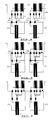
- FIG. 1 shows a first exemplary embodiment of a cabling system according to the invention.
- the cabling system is formed by a balanced network cable 1 which comprises two cores 2 and a screen 3 and which serves only for a point-to-point connection.
- the connecting cables 4 are connected to the network cable 1 via low-impedance interconnections 7 and 8, .i.e. the core 5 of each connecting cable 4 is connected to the two cores 2 of the network cable 1 via interconnection 7.
- the screen 6 of the connecting cable 4 is connected to the screen of the network cable 1 via interconnection 8.
- Figure 2 also shows point-to-point cabling which is, however, formed by two parallel balanced cables 1.
- the connecting cables 4 are connected to the network cable 1 via interconnections 7 and 8.
- the interconnections 7 are connected, on the one hand, to two cores of the one network cable 1 and one core of the second network cable 1 and, on the other hand, to the core of the respective connecting cable 4.
- the interconnections 8 are connected, on the one hand, to the screens of the two network cables 1 and, on the other hand, to the screen of the connecting cable 4.
- three parallel network cable cores 2 are thus connected to the respective connecting cable cores 5.
- This exemplary embodiment is used if the characteristic impedance of the connecting cable 4 is relatively low, whereas the preceding exemplary embodiment is used if the characteristic impedance of the connecting cable 4 is higher. If the characteristic impedance of the connecting cable 4 is still lower, it is also possible to connect the cores 5 via interconnection 7 to all four of the cores 2 of the network cables 1.
- Figure 3 shows a section of a cabling system according to the invention which is formed by more cable runs of the type shown in Figure 2.
- the cabling system serves a network having an electrically unbalanced bus structure such as Ethernet
- the connecting cables 4 shown are both connected to a (personal) computer where the cables are connected to each other and to the computer.
- the cabling system serves a network having an electrically balanced ring structure such as IBM Token Ring
- the connecting cables which are in that case electrically balanced like the network cables 1, are not connected via the interconnections 7 and 8 to the network cables 1 but are directly connected to one of those two.
- FIG. 4 shows an application example of the cabling system according to the invention.
- This Figure shows a building 10 which has a number of rooms 11 and in which cabling is installed which comprises cable runs 12 between each of said rooms 11 and a central distributor 13.
- Each of the cable runs 12 between the rooms 11 and the distributor 13 comprises, in this exemplary embodiment, a double pair of the parallel balanced screened cables 1 shown in Figures 2 and 3, with the result that, in addition to point-to-point connections, various network configurations such as those having a ring or bus structure can be formed.
- the cabling can either be used by network systems which, according to their specification, have to make use of balanced cabling or by network systems which require unbalanced cabling.
- the equipment is connected directly to the cable runs 12, (i.e. to one of the balanced cables 1 thereof), whereas in the latter case the equipment is connected to the cable runs 12 via the interconnections 7 and 8, mentioned above, by means of which, as it were, unbalanced cabling is simulated.
- the matching of the unbalanced connecting cables to the simulated unbalanced cabling is not completely perfect, and this forms a limitation to the number of cable runs 12 to be connected in series with one another; however, this number can be increased again by installing a so-called repeater after a number of cable runs 12 connected in series.
- FIG 5 shows the building 10 shown in Figure 4 with the cabling shown in Figure 4 therein, which building 10 has been put into use and in which the cabling system serves a number of separate transmission networks A, B, C and D.
- the network A is a ring-type network (for example, IBM Token Ring) which, in addition to being formed by the respective cable runs 12, is further formed by a number of personal computers 14 of which one operates as a network server. Said network A makes use of balanced cabling which is formed, in this exemplary embodiment, by one cable pair in each case from the respective cable runs 12 (which each comprise two cable pairs). Located between the two cables, debouching in the respective room 11, of the cable pair thus used are computers 14. In the central distributor 13, the cable ring is closed by looping the respective cables 12 debouching therein as a ring.
- IBM Token Ring IBM Token Ring
- the network B is a network having a bus structure (for example, Ethernet) formed by the series connection of a number of cable runs 12 to which a number of personal computers 15 are connected.
- This network is of a type which, according to the specifications, has to make use of unbalanced cabling.
- the unbalanced cabling is formed by the double cable pairs of the cable runs 12, the computers 15 being located between the two cable pairs debouching in the respective room 11 in the manner which is shown in Figure 3.
- the actual position of the interconnections 7 and 8 (see Figure 3) is dealt with in more detail.
- the cable pairs 1 debouching therein are looped through.
- the network C is also a network having a bus structure to which the personal computers 16 are connected as terminal pieces of equipment.
- the networks B and C are connected to each other via a coupling unit 19 which is installed in the distributor and through which information can be exchanged between these two independent networks.
- Figure 5 also shows a point-to-point connection D between two computers 17 in different rooms.
- This connection D is formed by two cable runs 12 connected in series in the central distributor 13.
- the computers 17 can be connected directly to one of the cables 1 of the cable run 12 debouching in the room (balanced connection) or via the interconnections 7 and 8 shown in Figures 1...3 (unbalanced connection).
- unbalanced (coaxial) connecting cables 4 can be connected to the network cables 1 via low-impedance interconnections between the cores 2 and 5 of the cables and between the screens 3 and 6 thereof. If, according to the network specifications, use must be made of balanced connecting cables (as in the case of network A) these are connected directly to the network cables 1 by connecting, in particular, the cores and the screen of the balanced connecting cable directly to those of one of the (balanced) network cables 1.
- the said interconnections (7 and 8 in Figures 1 ...3) between the respective cable cores and screens may form part of the permanent network connection at which the end of a cable run 12 is terminated in a room 11, or it may be incorporated in a separate adapter between such a permanent network connection and the connecting plug of the connecting cable 4, or it may be incorporated in the connecting plug itself.
- These alternatives are shown in Figures 6, 7 and 8.
- Figure 6 shows a permanent network connection 20 in which the end, debouching in a room II ( Figure 4), of a cable run 12, comprising a double set of balanced network cables 1, is terminated.
- a cable run 12 comprising a double set of balanced network cables 1
- three cores 2 of each set of balanced network cables 1 are terminated at interconnection 7 and the screen at interconnection 8.
- the other side of the interconnections 7 and 8 are connected to plug sockets 21 and 22.
- the terminal equipment to be connected to the network is connected to the plug sockets 21, and consequently to the network cables 1, via the connecting cable 4 which is terminated at a cable plug 23.
- the example shown in this Figure has the disadvantage that, if the connecting cable 4 has a relatively large characteristic impedance, one of the three cores 2 of the interconnection 7 has to be detached per set of network cables 1; this then has to be done in the permanent network connection 20. Equally, if the impedance of the connecting cable 4 is relatively low, the fourth core of each set of network cables 1 must also be connected to the interconnection 7. For these reasons it may be attractive to locate the interconnections 7 and 8 in a separate adapter, as Figure 7 shows.
- the interconnections 7 and 8 are located in an adapter 25 which is connected, by means of plug connections 26, to the network cables 1 and, by means of plug connections 27, to the connecting cables 4.
- an adapter 25 is used which is connected to one, two, three or four cores 2.
- Figure 8 shows an embodiment in which the interconnections 7 and 8 are located in a connecting cable plug 28, by which arrangement the use of a separate adapter is avoid severelyed.
Landscapes
- Engineering & Computer Science (AREA)
- Architecture (AREA)
- Civil Engineering (AREA)
- Structural Engineering (AREA)
- Selective Calling Equipment (AREA)
- Numerical Control (AREA)
- Pharmaceuticals Containing Other Organic And Inorganic Compounds (AREA)
- Cable Transmission Systems, Equalization Of Radio And Reduction Of Echo (AREA)
- Small-Scale Networks (AREA)
- Insulated Conductors (AREA)
- Cable Accessories (AREA)
Applications Claiming Priority (2)
| Application Number | Priority Date | Filing Date | Title |
|---|---|---|---|
| NL8902061 | 1989-08-14 | ||
| NL8902061A NL8902061A (nl) | 1989-08-14 | 1989-08-14 | Bekabelingssysteem voor een lokaal netwerk. |
Publications (2)
| Publication Number | Publication Date |
|---|---|
| EP0413380A1 true EP0413380A1 (de) | 1991-02-20 |
| EP0413380B1 EP0413380B1 (de) | 1994-06-22 |
Family
ID=19855163
Family Applications (1)
| Application Number | Title | Priority Date | Filing Date |
|---|---|---|---|
| EP90202053A Expired - Lifetime EP0413380B1 (de) | 1989-08-14 | 1990-07-27 | Verkabelungssysteme für ein lokales Netzwerk |
Country Status (5)
| Country | Link |
|---|---|
| EP (1) | EP0413380B1 (de) |
| AT (1) | ATE107805T1 (de) |
| DE (1) | DE69010110T2 (de) |
| DK (1) | DK0413380T3 (de) |
| NL (1) | NL8902061A (de) |
Cited By (1)
| Publication number | Priority date | Publication date | Assignee | Title |
|---|---|---|---|---|
| DE19923893A1 (de) * | 1999-05-25 | 2000-11-30 | Bayerische Motoren Werke Ag | Elektrisches Verdrahtungssystem für die Antriebseinheit in Fahrzeugen |
Citations (2)
| Publication number | Priority date | Publication date | Assignee | Title |
|---|---|---|---|---|
| EP0276615A1 (de) * | 1986-12-30 | 1988-08-03 | Jacques E. Nozick | Verkabelungsvorrichtung in einem Telefon- und/oder Datenniederspannungsnetz für ein Gebäude |
| DE3704617A1 (de) * | 1987-02-13 | 1988-08-25 | Sedlbauer Wilhelm Gmbh | Verkabelungssystem fuer gebaeude mit mehreren geschossebenen zum wahlweisen anschluss von edv-anlagen |
-
1989
- 1989-08-14 NL NL8902061A patent/NL8902061A/nl not_active Application Discontinuation
-
1990
- 1990-07-27 DE DE69010110T patent/DE69010110T2/de not_active Expired - Fee Related
- 1990-07-27 AT AT90202053T patent/ATE107805T1/de not_active IP Right Cessation
- 1990-07-27 EP EP90202053A patent/EP0413380B1/de not_active Expired - Lifetime
- 1990-07-27 DK DK90202053.6T patent/DK0413380T3/da active
Patent Citations (2)
| Publication number | Priority date | Publication date | Assignee | Title |
|---|---|---|---|---|
| EP0276615A1 (de) * | 1986-12-30 | 1988-08-03 | Jacques E. Nozick | Verkabelungsvorrichtung in einem Telefon- und/oder Datenniederspannungsnetz für ein Gebäude |
| DE3704617A1 (de) * | 1987-02-13 | 1988-08-25 | Sedlbauer Wilhelm Gmbh | Verkabelungssystem fuer gebaeude mit mehreren geschossebenen zum wahlweisen anschluss von edv-anlagen |
Cited By (2)
| Publication number | Priority date | Publication date | Assignee | Title |
|---|---|---|---|---|
| DE19923893A1 (de) * | 1999-05-25 | 2000-11-30 | Bayerische Motoren Werke Ag | Elektrisches Verdrahtungssystem für die Antriebseinheit in Fahrzeugen |
| US6577025B2 (en) | 1999-05-25 | 2003-06-10 | Lisa Draxlmaier Gmbh | Electrical wiring system for the drive unit in vehicles |
Also Published As
| Publication number | Publication date |
|---|---|
| DE69010110D1 (de) | 1994-07-28 |
| DK0413380T3 (da) | 1994-10-24 |
| NL8902061A (nl) | 1991-03-01 |
| ATE107805T1 (de) | 1994-07-15 |
| EP0413380B1 (de) | 1994-06-22 |
| DE69010110T2 (de) | 1995-01-12 |
Similar Documents
| Publication | Publication Date | Title |
|---|---|---|
| US7193422B2 (en) | Patch panel system | |
| US5107532A (en) | Automated documentation system for a communications network | |
| US5599190A (en) | Communication wiring system including a reconfigurable outlet assembly | |
| EP0374224B1 (de) | Tragbarer identifizierungsapparat für kommunikationskabel | |
| US5117122A (en) | Integrated outlet for communication and electrical power transmissions with noise reducing characteristics | |
| JP2002330506A (ja) | 分電盤、ジャンクションボックス、アウトレットボックス、電気コード付きプラグ、アウトレットボックス用端子盤、テーブルタップ及び宅内ネットワークシステム | |
| CN1111831A (zh) | 10基t网络的增强 | |
| EP0681347A2 (de) | Verbindungsmodul für lokales Netzwerk | |
| US7445520B2 (en) | Field communication and computer data distribution system | |
| JPS61247146A (ja) | リング通信システムの内線構成 | |
| US4886464A (en) | Remote interconnection box utilizing shielding interconnecting brackets | |
| JPS63174512A (ja) | ネットワ−ク配線方式 | |
| US5309092A (en) | Token ring test simulation method and device | |
| US20040235356A1 (en) | Cross-connector for interfacing multiple communication devices | |
| US6454597B1 (en) | Direct to closet wiring system | |
| US7625248B2 (en) | Field data distribution system with fiber optic converter | |
| EP0413380B1 (de) | Verkabelungssysteme für ein lokales Netzwerk | |
| US7625249B2 (en) | Quad field data distribution system with fiber optic converter | |
| US7961846B2 (en) | Interface device for testing a telecommunication circuit | |
| MXPA06006303A (es) | Disposicion de lampara visualizadora. | |
| KR20060023549A (ko) | 네트워크 연결 감지 어셈블리 | |
| Semenov et al. | Structured cable systems | |
| GB2361590A (en) | Adapter for connecting multiple telephones using a single eight-wire cable | |
| US5905316A (en) | Structured cabling | |
| US8355498B2 (en) | Communication line interface |
Legal Events
| Date | Code | Title | Description |
|---|---|---|---|
| PUAI | Public reference made under article 153(3) epc to a published international application that has entered the european phase |
Free format text: ORIGINAL CODE: 0009012 |
|
| 17P | Request for examination filed |
Effective date: 19901218 |
|
| AK | Designated contracting states |
Kind code of ref document: A1 Designated state(s): AT BE CH DE DK ES FR GB GR IT LI LU NL SE |
|
| 17Q | First examination report despatched |
Effective date: 19930430 |
|
| GRAA | (expected) grant |
Free format text: ORIGINAL CODE: 0009210 |
|
| AK | Designated contracting states |
Kind code of ref document: B1 Designated state(s): AT BE CH DE DK ES FR GB GR IT LI LU NL SE |
|
| PG25 | Lapsed in a contracting state [announced via postgrant information from national office to epo] |
Ref country code: IT Free format text: LAPSE BECAUSE OF FAILURE TO SUBMIT A TRANSLATION OF THE DESCRIPTION OR TO PAY THE FEE WITHIN THE PRE;WARNING: LAPSES OF ITALIAN PATENTS WITH EFFECTIVE DATE BEFORE 2007 MAY HAVE OCCURRED AT ANY TIME BEFORE 2007. THE CORRECT EFFECTIVE DATE MAY BE DIFFERENT FROM THE ONE RECORDED.SCRIBED TIME-LIMIT Effective date: 19940622 Ref country code: AT Effective date: 19940622 Ref country code: ES Free format text: THE PATENT HAS BEEN ANNULLED BY A DECISION OF A NATIONAL AUTHORITY Effective date: 19940622 Ref country code: GR Free format text: LAPSE BECAUSE OF FAILURE TO SUBMIT A TRANSLATION OF THE DESCRIPTION OR TO PAY THE FEE WITHIN THE PRESCRIBED TIME-LIMIT Effective date: 19940622 |
|
| REF | Corresponds to: |
Ref document number: 107805 Country of ref document: AT Date of ref document: 19940715 Kind code of ref document: T |
|
| REF | Corresponds to: |
Ref document number: 69010110 Country of ref document: DE Date of ref document: 19940728 |
|
| ET | Fr: translation filed | ||
| REG | Reference to a national code |
Ref country code: DK Ref legal event code: T3 |
|
| EAL | Se: european patent in force in sweden |
Ref document number: 90202053.6 |
|
| PLBE | No opposition filed within time limit |
Free format text: ORIGINAL CODE: 0009261 |
|
| STAA | Information on the status of an ep patent application or granted ep patent |
Free format text: STATUS: NO OPPOSITION FILED WITHIN TIME LIMIT |
|
| 26N | No opposition filed | ||
| PGFP | Annual fee paid to national office [announced via postgrant information from national office to epo] |
Ref country code: GB Payment date: 19980612 Year of fee payment: 9 |
|
| PGFP | Annual fee paid to national office [announced via postgrant information from national office to epo] |
Ref country code: SE Payment date: 19980624 Year of fee payment: 9 |
|
| PGFP | Annual fee paid to national office [announced via postgrant information from national office to epo] |
Ref country code: DK Payment date: 19980625 Year of fee payment: 9 Ref country code: LU Payment date: 19980625 Year of fee payment: 9 |
|
| PGFP | Annual fee paid to national office [announced via postgrant information from national office to epo] |
Ref country code: FR Payment date: 19980629 Year of fee payment: 9 Ref country code: NL Payment date: 19980629 Year of fee payment: 9 |
|
| PGFP | Annual fee paid to national office [announced via postgrant information from national office to epo] |
Ref country code: DE Payment date: 19980630 Year of fee payment: 9 |
|
| PGFP | Annual fee paid to national office [announced via postgrant information from national office to epo] |
Ref country code: CH Payment date: 19980701 Year of fee payment: 9 |
|
| PGFP | Annual fee paid to national office [announced via postgrant information from national office to epo] |
Ref country code: BE Payment date: 19980709 Year of fee payment: 9 |
|
| REG | Reference to a national code |
Ref country code: CH Ref legal event code: PFA Free format text: KONINKLIJKE PTT NEDERLAND N.V. TRANSFER- KONINKLIJKE KPN N.V. |
|
| PG25 | Lapsed in a contracting state [announced via postgrant information from national office to epo] |
Ref country code: GB Free format text: LAPSE BECAUSE OF NON-PAYMENT OF DUE FEES Effective date: 19990727 Ref country code: LU Free format text: LAPSE BECAUSE OF NON-PAYMENT OF DUE FEES Effective date: 19990727 |
|
| PG25 | Lapsed in a contracting state [announced via postgrant information from national office to epo] |
Ref country code: SE Free format text: THE PATENT HAS BEEN ANNULLED BY A DECISION OF A NATIONAL AUTHORITY Effective date: 19990730 |
|
| PG25 | Lapsed in a contracting state [announced via postgrant information from national office to epo] |
Ref country code: FR Free format text: THE PATENT HAS BEEN ANNULLED BY A DECISION OF A NATIONAL AUTHORITY Effective date: 19990731 Ref country code: LI Free format text: LAPSE BECAUSE OF NON-PAYMENT OF DUE FEES Effective date: 19990731 Ref country code: BE Free format text: LAPSE BECAUSE OF NON-PAYMENT OF DUE FEES Effective date: 19990731 Ref country code: CH Free format text: LAPSE BECAUSE OF NON-PAYMENT OF DUE FEES Effective date: 19990731 |
|
| PG25 | Lapsed in a contracting state [announced via postgrant information from national office to epo] |
Ref country code: DK Free format text: LAPSE BECAUSE OF NON-PAYMENT OF DUE FEES Effective date: 19990802 |
|
| BERE | Be: lapsed |
Owner name: KONINKLIJKE PTT NEDERLAND N.V. Effective date: 19990731 |
|
| PG25 | Lapsed in a contracting state [announced via postgrant information from national office to epo] |
Ref country code: NL Free format text: LAPSE BECAUSE OF NON-PAYMENT OF DUE FEES Effective date: 20000201 |
|
| GBPC | Gb: european patent ceased through non-payment of renewal fee |
Effective date: 19990727 |
|
| REG | Reference to a national code |
Ref country code: CH Ref legal event code: PL |
|
| REG | Reference to a national code |
Ref country code: DK Ref legal event code: EBP |
|
| EUG | Se: european patent has lapsed |
Ref document number: 90202053.6 |
|
| NLV4 | Nl: lapsed or anulled due to non-payment of the annual fee |
Effective date: 20000201 |
|
| PG25 | Lapsed in a contracting state [announced via postgrant information from national office to epo] |
Ref country code: DE Free format text: LAPSE BECAUSE OF NON-PAYMENT OF DUE FEES Effective date: 20000503 |
|
| REG | Reference to a national code |
Ref country code: FR Ref legal event code: ST |