EP0414450A2 - Antriebseinheiten für optische Platte - Google Patents
Antriebseinheiten für optische Platte Download PDFInfo
- Publication number
- EP0414450A2 EP0414450A2 EP90309037A EP90309037A EP0414450A2 EP 0414450 A2 EP0414450 A2 EP 0414450A2 EP 90309037 A EP90309037 A EP 90309037A EP 90309037 A EP90309037 A EP 90309037A EP 0414450 A2 EP0414450 A2 EP 0414450A2
- Authority
- EP
- European Patent Office
- Prior art keywords
- offset
- drive
- actuator
- light
- optical
- Prior art date
- Legal status (The legal status is an assumption and is not a legal conclusion. Google has not performed a legal analysis and makes no representation as to the accuracy of the status listed.)
- Granted
Links
Images


Classifications
-
- G—PHYSICS
- G11—INFORMATION STORAGE
- G11B—INFORMATION STORAGE BASED ON RELATIVE MOVEMENT BETWEEN RECORD CARRIER AND TRANSDUCER
- G11B7/00—Recording or reproducing by optical means, e.g. recording using a thermal beam of optical radiation by modifying optical properties or the physical structure, reproducing using an optical beam at lower power by sensing optical properties; Record carriers therefor
- G11B7/08—Disposition or mounting of heads or light sources relatively to record carriers
- G11B7/085—Disposition or mounting of heads or light sources relatively to record carriers with provision for moving the light beam into, or out of, its operative position or across tracks, otherwise than during the transducing operation, e.g. for adjustment or preliminary positioning or track change or selection
- G11B7/08547—Arrangements for positioning the light beam only without moving the head, e.g. using static electro-optical elements
- G11B7/08564—Arrangements for positioning the light beam only without moving the head, e.g. using static electro-optical elements using galvanomirrors
-
- G—PHYSICS
- G11—INFORMATION STORAGE
- G11B—INFORMATION STORAGE BASED ON RELATIVE MOVEMENT BETWEEN RECORD CARRIER AND TRANSDUCER
- G11B7/00—Recording or reproducing by optical means, e.g. recording using a thermal beam of optical radiation by modifying optical properties or the physical structure, reproducing using an optical beam at lower power by sensing optical properties; Record carriers therefor
- G11B7/08—Disposition or mounting of heads or light sources relatively to record carriers
- G11B7/085—Disposition or mounting of heads or light sources relatively to record carriers with provision for moving the light beam into, or out of, its operative position or across tracks, otherwise than during the transducing operation, e.g. for adjustment or preliminary positioning or track change or selection
- G11B7/08505—Methods for track change, selection or preliminary positioning by moving the head
- G11B7/08517—Methods for track change, selection or preliminary positioning by moving the head with tracking pull-in only
-
- G—PHYSICS
- G11—INFORMATION STORAGE
- G11B—INFORMATION STORAGE BASED ON RELATIVE MOVEMENT BETWEEN RECORD CARRIER AND TRANSDUCER
- G11B7/00—Recording or reproducing by optical means, e.g. recording using a thermal beam of optical radiation by modifying optical properties or the physical structure, reproducing using an optical beam at lower power by sensing optical properties; Record carriers therefor
- G11B7/08—Disposition or mounting of heads or light sources relatively to record carriers
- G11B7/09—Disposition or mounting of heads or light sources relatively to record carriers with provision for moving the light beam or focus plane for the purpose of maintaining alignment of the light beam relative to the record carrier during transducing operation, e.g. to compensate for surface irregularities of the latter or for track following
- G11B7/094—Methods and circuits for servo offset compensation
-
- G—PHYSICS
- G11—INFORMATION STORAGE
- G11B—INFORMATION STORAGE BASED ON RELATIVE MOVEMENT BETWEEN RECORD CARRIER AND TRANSDUCER
- G11B7/00—Recording or reproducing by optical means, e.g. recording using a thermal beam of optical radiation by modifying optical properties or the physical structure, reproducing using an optical beam at lower power by sensing optical properties; Record carriers therefor
- G11B7/08—Disposition or mounting of heads or light sources relatively to record carriers
- G11B7/09—Disposition or mounting of heads or light sources relatively to record carriers with provision for moving the light beam or focus plane for the purpose of maintaining alignment of the light beam relative to the record carrier during transducing operation, e.g. to compensate for surface irregularities of the latter or for track following
- G11B7/0941—Methods and circuits for servo gain or phase compensation during operation
Definitions
- the present invention relates to optical disk drive units.
- tracking control by which a beam spot can accurately trace the track, may be provided, and an optical head mounted on a carriage may be provided with a tracking actuator which moves the beam spot in a radial direction within a predetermined range of the track width in the carriage stationary state.
- the tracking actuator may comprise a magnetic field structure, as a stationary member, and a rotation member provided with a tracking coil. The beam spot from an object lens is moved perpendicular to the track of the optical disk by providing an object lens of a head optical system at the rotation member side, and by rotating the rotation member by supplying an electric power to the tracking coil.
- the tracking control can be accomplished by a feedback control of a supply of an electric current through the tracking coil, whereby a tracking detection signal is held at zero, in accordance with a tracking error detection signal obtained as a difference of an output obtained by making a light reflected from the disk incident on a two-divided photodiode, through the head optical system.
- a position detector using a two-divided phtodiode for detecting a neutral position of the rotation member of the tracking actuator i.e., a position at which the rotation is stopped when the electric power supplied to the coil is cut, may be provided, and the position signal in the track direction (radial directions is detected as a difference of the two incident lights.
- the track position detection signal is used for a control of the holding of the head carriage, which is controlled by a voice coil motor, and holds the rotation member of the actuator at the neutral position by supplying a drive current to the voice coil motor so as to hold the track direction position detection signal at zero.
- the actuator is controlled by a double servocontrol wherein the actuator is controlled by the feedback control to the tracking coil receiving the tracking error signal and to the voice-coil motor receiving the track direction position signal.
- the rotation member of the tracking actuator may be provided with a spring member for returning the rotation member to the neutral position when the electric current supplied to the coil is cut off, but the balance of the position of the rotation member when held by the spring member does not always coincide with the neutral position whereat the detection signal of the position detector is zero.
- the control has a response characteristic at the track jump that is not adversely affected, because the offset due to the spring force is suppressed.
- a first embodiment of the present invention can provide a device for eliminating an offset of an actuator comprising an actuator including a fixed member, a moving member mounted on the fixed member, a drive means provided on the moving member, a spring member for holding the moving member to the fixed member at a predetermined neutral position when an electric power is not supplied to the drive means, and a position detection means for detecting the neutral position of the moving member when held by the spring member; an offset measuring means for changing an electric drive current of the drive means and for storing and holding a value of an electric current supplied to the drive means when the detection output of a neutral position by the position detection means is obtained, in an offset measuring mode; and an offset elimination means for eliminating the offset included in a moving means drive error signal by constantly supplying the electric drive current offset value stored and held in the offset measuring means to the drive means in the usual operation mode.
- a second embodiment of the invention can provide an optical disk device for eliminating an offset of an actuator, comprising an actuator including a magnetic field structure, a rotation member rotatably mounted on the magnetic field structure, a tracking coil provided on the rotation member, a spring member for holding the rotation member at a predetermined neutral position when an electric power is not supplied to the tracking coil, and a position detection means for detecting the neutral position of the rotation member when held by the spring member; an offset measuring means for changing an electric drive current of the tracking coil and for storing and holding a value of an electric current supplied to the tracking coil when the detection output of a neutral position by the position detection means is obtained, in a offset measuring mode; and an offset elimination means for eliminating the offset included in a tracking error signal by constantly supplying the electric drive current offset value stored and held in the offset measuring means to the tracking coil in the usual operation mode.
- a third embodiment of the invention can provide an optical disk device for eliminating an offset of an actuator comprising an actuator including a galvanomirror for reflecting light from a light source in a substantially perpendicular direction, an object lens for receiving the light reflected from the galvanomirror and supply the light to the optical disk, a position detection means for projecting a light from a light source to a two-divided optical sensor through another reflection surface of the galvamiorror and for detecting a neutral position thereof, and a spring member attached to the galvanomirror for balancing the galvanomirror in a balanced position thereof; an offset measuring means for changing an electric drive current of a drive means of the galvanomirror and for storing and holding an electric drive current value when the output of a detection of a neutral position by the position detection means is obtained, in a offset measuring mode; and an offset elimination means for eliminating the offset in a tracking error signal by constantly supplying the electric drive current offset value stored an held in the offset measuring means to a drive
- a fourth embodiment of the invention can provide an optical disk device for eliminating an offset of an actuator comprising an actuator including a relay lens for receiving light from a light source, a mirror for reflecting the light from the relay lens in a substantially perpendicular direction, an object lens receiving the light reflected from the mirror and for illuminating an optical disk, a spring member for connecting the relay lens to a fixed board, and a position detection means having a slit connected to the relay lens and responsive to the movement of the relay lens in the direction perpendicular to the incident light, a light emitting source for supplying light therefrom to the slit, and a two-divided optical sensor for receiving the light from the light emitting source through the slit; an offset measuring means for changing an electric drive current of a drive means of the relay lens and for storing and holding a electric drive current value when the output of a detection of a neutral position by the position detection means is obtained, in an offset measuring mode; and an offset elimination means for eliminating the offset in a tracking error signal by constantly suppling the
- a further embodiment according to a different aspect of the invention can provide a method of eliminating an offset in an optical disk device having an actuator including a moving member for a fine adjustment of a tracking control when accessing an optical disk, a spring member for holding the moving member at a predetermined balanced position thereof, and a position detection means for detecting a neutral position of the moving member, the method comprising the steps of increasing or decreasing an electric drive current supplied to the moving member, by a predetermined step when released from the tracking control, storing the electric drive current value as an offset current when a position detection error signal by the position detection means becomes zero, and supplying the offset current as an electric drive current to the moving member in a tracking control state.
- Figure 8 shows an actuator for tracking as used in an optical disk device. This is known as a two-dimensional actuator because a tracking control and a focusing control are executed simulataneously thereby.
- the actuator comprises a magnetic field structure 10, as a stationary member having a sliding shaft 12, and a rotation member 18 as a rotary member.
- the rotation member 18 comprised a cylinder 14 and an upper rotary arm 16, as one body, and the cylinder 14 is provided with a tracking coil 20.
- the rotary arm 16 is provided with an object lens 22 at one end and a balance weight 32 at the other end.
- a focusing coil 34 is wound inside the tracking coil 20.
- Figure 9 shows a plan view of the actuator, wherein lead wires from the magnetic field structure 10 to the tracking coil 20 and focusing coil 34 provided on the rotation member 18 act as spring members 24, whereby the rotation member 18 is held at the neutral position when an electric current passed through the coil 20 is cut off, as shown in the Fig. 9.
- Figure 10 shows a constitution of the position detector provided in the actuator, wherein a projecting slit member 40, provided with a slit hole 38 at the lower portion in the balance weight side of the rotary arm 16, allows light from a light-emitting diode (LED) 42 provided at the inner side of the slit member 40 to be supplied to a two-divided photodiode 26 acting as a position detector and arranged to face the LED 42 through the slit hole 38.
- LED light-emitting diode
- Fig. 11 shows a detection circuit for detecting the track direction position signal from the two-divided photodiode 26 shown in Fig. 10, wherein a difference signal is obtained from two incident lights by supplying two light signals from two light reception portions A and B to a differential amplifier 44.
- the rotation member of the actuator is at the neutral position, as shown in the figure, the spot light is supplied so that the light reception portions A and B are symmetric, and an output signal of the differential amplifier 44 becomes zero when the rotation member is at the neutral position.
- the detection signal is increased in response to the amount of rotation, and a difference in the polarity thereof according to the rotation direction is obtained.
- Figure 1 is an explanatory diagram of the previously-considered servocontrol system of the actuator.
- an optical disk 46 is rotated constantly by a spindle motor 48, and an optical head 100 mounted on a carriage 52 is moved radially over the optical disk 46 by a voice coil motor 50.
- the actuator is mounted on the optical head 100 as shown in Figs. 8, 9, and 10, and is provided with the two-divided photodiode 26 for position detection and the two-divided photodiode, which receives light reflected from the disk, for the tracking error detection.
- the two outputs of the two-part photodiode for position detection are supplied to the differential amplifier 44, a track direction position signal LPOS showing both the track direction (polarity) and the track position (signal intensity) as a difference thereof is detected, and after phase compensation emphasizing a high frequency component, by a phase compensation circuit 54, a power amplifier 56 drives the voice coil motor 50 and controls the track direction position signal to zero.
- the two outputs of the light reflected from the disk from the two-divided photodiode are obtained by the head optical system and supplied to a differential amplifier 58, the tracking error signal TES is detected as a difference thereof, and the signal drives the tracking coil through a phase compensation circuit 60 and a power amplifier 62 so that the feedback control is executed to hold the tracking error signal TES at zero.
- the position of the rotation member 18 when balanced by the spring members 24, shown in Fig. 13, usually does not coincide with the zero signal position of the detection signal LPOS from the two-divided photodiode for the position detection shown in Fig. 8, and thus a problem arises in that, when the double servocontrol is executed by the feedback controls of the tracking coil and the voice coil motor, an offset due to the spring force is generated in the tracking error signal TES, and when a track jump is executed an overshoot or undershoot occurs and the stability and the response characteristic are lowered.
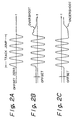
- Figures 2A, 2B, and 2C show an effect of the tracking error signal TES due to the spring force, at the track jump.
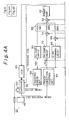
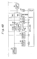
- FIGS. 4A and 4B are block diagrams showing a tracking control circuit of an optical disk device embodying the present invention.
- 100 is an optical head mounted on a carriage 52 driven by a voice coil motor 50, and the optical head 100 is moved radially over an optical disk 46 rotated at a constant revolution speed by a spindle motor 48.
- the optical head 100 is provided with an actuator, as shown in Fig. 8, Fig. 12, and Fig. 13, and a tracking coil 20 provided in the actuator moves the light beam within a predetermined number of tracks when the carriage 52 is stationary.
- FIG. 5 An example of a constitution of a head optical system provided in the optical head 100 is shown in Fig. 5.
- 102 is a semiconductor laser
- 104 is a collimator lens converting elliptical diffused light from the semiconductor laser 102 to a circular parallel beam
- 106 is a polarized light beam splitter composed of a combination of two prisms, and passing a P (component) polarized light as is while reflecting an S (component) polarized light in the perpendicular direction
- 108 is a ⁇ /4 plate converting incident linear polarized light to circularly polarized light, or incident circularly polarized light to linear polarized light
- 22 is an object lens for illuminating the optical disk 46 with a beam spot, which beam spot has a track pitch of 1.6 micrometers
- 110 is a converging lens for converging light reflected from the optical disk 46, which reflected light is reflected in the perpendicular direction by the polarized light beam splitter 106
- 112 is a two-divided photodiode for detecting a tracking error and generating an output
- the tracking error detection output from the two-divided photodiode 112 provided in the light head 100 is supplied to a tracking error detector 58, and the tracking error signal TES is detected as a difference of two outputs. Further, two outputs from a position detector 26 using a two-divided photodiode provided in the actuator are supplied to a track direction position detection circuit 44, and a track direction position detection signal LPOS is detected as a difference of the two outputs.
- the track direction position detection signal LPOS indicates a track position by the signal intensity, and a track direction by the signal polarity.
- the tracking error signal TES from the tracking error detector 58 is supplied to a phase compensation (PH. COMP.) circuit 60 and a velocity signal (V. SIG.) forming circuit 66.
- the output of the phase compensation circuit 60 is supplied to a power amplifier (POWER AMP.) 62 through a transfer switch SW1 provided in a mode switching circuit 64, and the output of the velocity signal forming circuit 66 is supplied to the power amplifier 62 through an adder 68 and a transfer switch SW3 of the mode switching circuit 64.
- the transfer switch SW1 of the mode switching circuit 64 is turned ON when the tracking servo is operated, and at that time, the transfer switch SW3 connected to the velocity signal forming circuit 66 is made OFF.
- the transfer switch SW3 is turned ON when a track jump occurs, and at that time, the transfer switch SW1 is turned OFF and the tracking servo is made off.
- a target velocity signal Vr2 is supplied to the adder 68 receiving the output of the velocity signal forming circuit 66 from the MPU (microprocessor unit) 200 through a D/A (digital to analog) converter 70, the adder 68 generates a. velocity error signal, and the velocity of the tracking coil 20 is controlled at the track jump.
- the detection signal LPOS of the track direction position detector 44 is supplied to the power amplifier 62 through a phase compensation circuit 72, an adder 74, and a transfer switch SW2 of the mode switching circuit 64.
- the transfer switch SW2 is turned ON upon a track pull-in after a rough access by the voice coil motor 50 is finished, and is turned OFF when the tracking servo is operated by turning ON the transfer switch SW1 after the track pull-in is completed.
- the transfer switch SW3 is made ON, the transfer switch SW2 and the transfer switch SW1 are turned OFF.
- a pre-measured eccentric amount(ECCEN.) of the optical disk 46 is given to the adder 74, by the MPU 200, through the D/A converter 76, in synchronization with the disk rotation, as a reference eccentric amount.
- the error signal of the position detection signal LPOS following the track eccentric amount is generated from the adder 74, and as a result, the power amplifier 62 supplies an electric current through the tracking coil 20 so that the actuator is moved by the pre-measured track eccentric amount.
- the detection signal TES of the tracking error detector 58 is waveformed by a shaping circuit 76 and supplied to the MPU 200 as a track crossing pulse TCP.
- the MPU 200 counts the track crossing pulses TCP at the track jump, and after reaching the target track number, the velocity contol is transferred to the position control.
- the movement of the carriage 52 by the voice coil motor 50 is detected by a linear encoder 78, the detection signal of the linear encoder 78 is supplied to a velocity signal forming circuit 80, and the carriage velocity is detected.
- the velocity signal of the velocity signal forming circuit 80 is compared with the target velocity Vr1 given by the MPU 200 through a D/A converter 84 to an adder 82, and the velocity error signal is generated and supplied to a power amplifier 56 through a transfer switch SW4, and thus the velocity of the voice coil motor 50 is controlled.
- the detection signal LPOS of the track direction position detector 44 is supplied to a phase compensation circuit 54, the output of the phase compensation circuit 54 is supplied to the power amplifier 56 through a transfer switch SW5, and the power amplifier 56 controls the voice coil motor 50 to execute a position control such that the track direction position detection signal LPOS becomes zero in accordance with the track direction position detection signal LPOS.
- the output of the linear encoder 78 is supplied to the MPU 200 through a shaping circuit 86, as a position pulse POSP, the MPU 200 counts the position pulse POSP obtained at the track access by the velocity control of the voice coil motor 50, by turning ON the transfer switch SW4. After reaching the target position, the transfer switch SW4 is turned OFF, and simultaneously, the transfer switch SW5 is turned ON, and thus the velocity control is switched to the position control.
- the optical disk device of figures 4A and 4B also comprises a comparator 88 for determining whether or not the detection signal LPOS of the track direction position detector 44 has reached a zero signal state indicating a neutral position, a D/A converter 90 for constantly supplying an offset current through the tracking coil 20 at the usual operation mode, which offset current is measured at the offset measuring mode, and an adder 92 for adding the offset at the preceding stage of the power amplifier 62.
- the MPU 200 has a function of controlling the offset measuring means and the offset eliminating means.
- the MPU 200 outputs the decreasing offset data and converts it to the analog signal, when all the transfer switches SW1 to SW5 of the mode switching circuit 64 are OFF, for the D/A converter 90 during the predetermined step after starting a predetermined initial value, and the driving current supplied to the tracking coil 20 of the actuator by a supply thereof to the power amplifier 62 from the adder 92 is sequentially decreased.
- the detection signal LPOS of the track direction position detector 44 in accordance with the position detector 26 is supervised by the comparator 88, and the MPU 200 stores and holds the offset data in the D/A converter 90 at that time, according to the output of the comparator 88 when the track direction position detection signal LPOS becomes a zero signal.
- the offset data stored and held in the offset measuring mode is constantly supplied to the D/A converter 90 and added to the control signal obtained from the mode switching circuit 64 by the adder 92, and the offset of the tracking error signal due to the spring force of the actuator is eliminated.
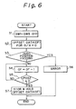
- Figure 6 is a flowchart showing an offset measuring process carried out by the MPU 200 in the device of Figs. 4A and 4B.
- Fig. 6 if the offset measuring mode is set to the MPU 200, at least the transfer switches SW1 to SW5 provided in the mode switching circuit 64 are turned OFF at step 1, and the preparation for the measuring is executed.
- step S2 the offset data OF for the D/A converter 90 is set to zero, and then to step S3, wherein the output of the comparator 88 is examined to determine whether or not the output has changed form 1 to 0 or 0 or 1, when the offset data is in the zero state. At that time, if the zero position where in the output changes from 0 to 1 or from 1 to zero, is determined, the actuator itself is considered faulty, and the process proceeds to step S6, and after the error is reported, the measuring process ends.
- step S4 for example, the maximum positive offset data value is set, the offset data is initially output as is, and the process proceeds to step S5. Then it is determined whether the output of the comparator 88 has reached zero, and if the output has not reached zero, the process returns to step S4.
- step S4 the offset data is decreased by 1 step (usually equal to the resolution of the D/A converter), and the processes of steps S4 and S5 are repeated.
- step S5 When the zero position wherein the output of the comparator 88 changes from 1 to 0 is detected in step S5, during the process of the repeated decrease of the offset data by one step in steps S4 and S5, the process proceeds to step S7 and the offset data OF at that time is stored and held, and then the process is ended.
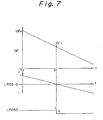
- Figure 7 shows a waveform diagram of the signals in the offset measuring process operation in Fig. 6.
- the initial offset data OF0 is set to the D/A converter 90 at time t0
- the track direction position signal LPOS corresponding to the offset data is obtained, and subsequently, the offset data is decreased 1 step by 1 step.
- the track direction position detection signal LPOS is decreased; if the track direction position detection signal LPOS reaches zero at the time t1, the track zero position signal LPOSZ as an output of the comparator is inverted from 1 to 0, and the offset data OF1 at that time is stored and held in the MPU 200.
- the offset data obtained by the offset measuring process, as shown in Figs. 6 and 7, in the usual operation mode is supplied to the D/A converter 90, the offset signal converted to an analog signal by the D/A converter 90 is supplied to the power amplifier 62 through the adder 92, and the offset signal is constantly applied to the tracking coil 20. Therefore, if the balanced position by the spring member of the actuator is different from the zero signal detection position by the position detector 26, the rotation of the actuator is maintained, so that the difference is eliminated, by the offset current passing through the tracking coil.
- the actuator is driven by the offset current and the neutral position due to the spring member always coincides with the zero signal position by the position detector 26, and accordingly, the servocontrol using the voice coil motor 50 to correct the position difference is not executed. Therefore, if the unbalance due to the spring member exists, the offset of the tracking error signal TES can be always suppressed to zero. Thus, if the track jump is carried out, since the tracking error signal has no offset, due to the velocity control of the actuator coil wherein, as soon as the transfer swithes SW1 and SW2 are tuned OFF the transfer switch SW3 is turned ON, at the end of the track jkump the tracking error signal is rapidly converged to the zero position.
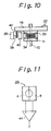
- the galvanomirror type actuator shown in Fig. 12 is provided with a galvanomirror 91, which is tracking controlled, held at the neutral position by a spring member 24, and a position detector comprises a reflection surface 93 of the mirror support portion, a light emitting portion 42, and a two-part photodiode 26.
- the galvanomirror is moved by an electric current as shown by arrow.
- This actuator is applied to the embodiment of Figs. 4A and 4B as is.
- 96 is a focus actuator.
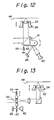
- the relay lens type actuator of Fig. 13 the relay lens 94 is moved perpendicular to the optical axis by an electric current and the tracking control is carried out.
- the position of the lens is balanced by a spring member 24 at a neutral position.
- This actuator further comprises a slit plate 40, a light emitting portion 42, and a two-divided photodiode 26.
- the light from the light emitting portion 42 is supplied to the two-divided photodiode through the slit plate 40.
- These elements constitute the position detector. Accordingly, the relay lens type actuator can be applied to the above-mentioned embodiment of Figs. 4A and 4B as is.
- the optical disk device with the servo controls wherein the offset of the track direction position detection signal is eliminated and the eccentric distance is eliminated in accordance with the track eccentric distance of the optical disk previously measured is explained, however, the described offset elimination process is applicable to an optical disk device not provided with the cancel control of this track eccentric distance.
- an offset is generated in the tracking error signal owing to an unbalanced spring force, corresponding to a difference between the equilibrium position, towards which the spring member tends to urge the actuator rotation member, and the desired neutral position (zero signal position) of the position detector, the offset is eliminated by constantly applying a premeasured electric bias current, for offset compensation, to the tracking coil, thereby effectively bringing the equilibrium position due to the spring member into coincidence with the desired neutral position of the position detector.
- the stability and the response characteristic can be increased at the track jump and a high speed track access can be realised.
Landscapes
- Optical Recording Or Reproduction (AREA)
- Moving Of The Head For Recording And Reproducing By Optical Means (AREA)
Applications Claiming Priority (2)
| Application Number | Priority Date | Filing Date | Title |
|---|---|---|---|
| JP213421/89 | 1989-08-19 | ||
| JP1213421A JP2593941B2 (ja) | 1989-08-19 | 1989-08-19 | 光ディスク装置のアクチュエータオフセット除去装置 |
Publications (3)
| Publication Number | Publication Date |
|---|---|
| EP0414450A2 true EP0414450A2 (de) | 1991-02-27 |
| EP0414450A3 EP0414450A3 (en) | 1991-11-27 |
| EP0414450B1 EP0414450B1 (de) | 1995-05-17 |
Family
ID=16638947
Family Applications (1)
| Application Number | Title | Priority Date | Filing Date |
|---|---|---|---|
| EP90309037A Expired - Lifetime EP0414450B1 (de) | 1989-08-19 | 1990-08-17 | Antriebseinheiten für optische Platte |
Country Status (4)
| Country | Link |
|---|---|
| US (1) | US5189653A (de) |
| EP (1) | EP0414450B1 (de) |
| JP (1) | JP2593941B2 (de) |
| DE (1) | DE69019437T2 (de) |
Cited By (2)
| Publication number | Priority date | Publication date | Assignee | Title |
|---|---|---|---|---|
| EP0757344A3 (de) * | 1995-07-31 | 1998-01-28 | Kabushiki Kaisha Toshiba | Optische Kopfeinheit zur Verwendung in einem Datenaufzeichnungs- und -wiedergabegerät |
| CN101551656B (zh) * | 2008-03-31 | 2012-06-20 | 索尼株式会社 | 信息处理设备和方法、程序和记录/再现设备 |
Families Citing this family (25)
| Publication number | Priority date | Publication date | Assignee | Title |
|---|---|---|---|---|
| US5265079A (en) | 1991-02-15 | 1993-11-23 | Applied Magnetics Corporation | Seek actuator for optical recording |
| US6141300A (en) | 1989-06-20 | 2000-10-31 | Discovision Associates | Optical actuator including lens assembly with optical axis having symmetric suspensory forces acting thereon and optical disc system including same |
| US5448540A (en) * | 1990-09-21 | 1995-09-05 | Victor Company Of Japan, Ltd. | Device for detecting the position of a recording/reproducing element |
| US5729511A (en) | 1991-02-15 | 1998-03-17 | Discovision Associates | Optical disc system having servo motor and servo error detection assembly operated relative to monitored quad sum signal |
| US6069857A (en) | 1991-02-15 | 2000-05-30 | Discovision Associates | Optical disc system having improved circuitry for performing blank sector check on readable disc |
| US5677899A (en) | 1991-02-15 | 1997-10-14 | Discovision Associates | Method for moving carriage assembly from initial position to target position relative to storage medium |
| US6236625B1 (en) | 1991-02-15 | 2001-05-22 | Discovision Associates | Optical disc system having current monitoring circuit with controller for laser driver and method for operating same |
| JP2682748B2 (ja) * | 1991-03-05 | 1997-11-26 | 富士通株式会社 | 光記録媒体のトラック横断信号作成回路 |
| JP2930750B2 (ja) * | 1991-03-06 | 1999-08-03 | パイオニア株式会社 | 光学式記録装置 |
| JPH05109092A (ja) * | 1991-10-14 | 1993-04-30 | Sony Corp | 光テープ記録再生装置 |
| US5475661A (en) * | 1992-04-07 | 1995-12-12 | Matsushita Electric Industrial Co., Ltd. | Objective lens actuator having frame-shaped leaf springs for minimizing focusing and tracking errors |
| US5543292A (en) * | 1992-06-16 | 1996-08-06 | Hitachi, Ltd. | Process for the measurement of nucleic acids |
| US5566152A (en) * | 1992-10-21 | 1996-10-15 | Matsushita Electric Industrial Co., Ltd. | Tracking control system with correction capabilities for correcting disagreement between optical axes |
| JP3263258B2 (ja) * | 1994-09-30 | 2002-03-04 | 富士通株式会社 | 光ディスク装置のアクチュエータオフセット量検出方法及び装置 |
| US6091684A (en) | 1995-01-25 | 2000-07-18 | Discovision Associates | Optical disc system and method for changing the rotational rate of an information storage medium |
| US5748578A (en) | 1995-01-25 | 1998-05-05 | Discovision Associates | Colpitts type oscillator having reduced ringing and improved optical disc system utilizing same |
| US6434087B1 (en) | 1995-01-25 | 2002-08-13 | Discovision Associates | Optical disc system and method for controlling bias coil and light source to process information on a storage medium |
| JP3550836B2 (ja) * | 1995-10-19 | 2004-08-04 | ソニー株式会社 | 光学装置におけるトラッキングサーボ装置及びトラッキングサーボ方法 |
| DE19630887A1 (de) * | 1996-07-31 | 1998-02-05 | Thomson Brandt Gmbh | Gerät zum Lesen und/oder Beschreiben optischer Aufzeichnungsträger |
| JP3588519B2 (ja) * | 1996-08-19 | 2004-11-10 | 富士通株式会社 | 光学的記憶装置 |
| KR100518514B1 (ko) | 1998-02-20 | 2005-11-24 | 삼성전자주식회사 | 하드 디스크 드라이브에서 엑츄에이터 온트랙 제어장치및 그방법 |
| JP2001204463A (ja) * | 2000-01-27 | 2001-07-31 | Toyo Kohan Co Ltd | ヌクレオチド固定用担体 |
| TWI316243B (en) * | 2005-07-14 | 2009-10-21 | Quanta Storage Inc | A seeking method of an optical disk player |
| US7400567B2 (en) * | 2005-11-29 | 2008-07-15 | Canon Kabushiki Kaisha | Optical information recording-reproduction apparatus |
| US8760833B2 (en) * | 2012-02-14 | 2014-06-24 | Hewlett Packard Development Company, L.P. | Apparatus and methods for limiting surges in load current |
Family Cites Families (12)
| Publication number | Priority date | Publication date | Assignee | Title |
|---|---|---|---|---|
| NL7812111A (nl) * | 1978-12-13 | 1980-06-17 | Philips Nv | Inrichting voor het optisch uitlezen van een schijf- vormige registratiedrager, in het bijzonder het snel opzoeken van een gewenst programmagedeelte. |
| FR2497378B1 (fr) * | 1980-12-29 | 1985-06-28 | Thomson Csf | Dispositif compensateur de desequilibre d'un miroir de renvoi appartenant a un systeme optique d'eclairement d'un support d'information |
| US4674076A (en) * | 1982-05-19 | 1987-06-16 | Burroughs Corporation | Optical memory system having improved positioning and focusing control circuitry |
| JPS5928255A (ja) * | 1982-08-05 | 1984-02-14 | Aiwa Co Ltd | 光学式情報再生装置 |
| JPS5977639A (ja) * | 1982-10-25 | 1984-05-04 | Hitachi Ltd | 光ディスク記録再生方法 |
| JPS59168835U (ja) * | 1983-04-27 | 1984-11-12 | パイオニア株式会社 | 光学式記録情報読取装置 |
| DE3324861C2 (de) * | 1983-07-09 | 1986-02-13 | Deutsche Thomson-Brandt Gmbh, 7730 Villingen-Schwenningen | Lesevorrichtung zum optischen Abtasten von auf einem bewegten plattenförmigen Träger aufgezeichneten Informationen |
| JPS61208641A (ja) * | 1985-03-13 | 1986-09-17 | Olympus Optical Co Ltd | 光学的情報記録再生装置 |
| US4768180A (en) * | 1986-03-17 | 1988-08-30 | Laser Magnetic Storage International Company | Multistage tracking system |
| JPS62219335A (ja) * | 1986-03-20 | 1987-09-26 | Ricoh Co Ltd | トラツク信号検出方法 |
| JPS6437729A (en) * | 1987-08-04 | 1989-02-08 | Canon Kk | Optical information recording and reproducing device |
| JPH0196835A (ja) * | 1987-10-07 | 1989-04-14 | Csk Corp | 光メモリカードのトラッキング装置 |
-
1989
- 1989-08-19 JP JP1213421A patent/JP2593941B2/ja not_active Expired - Fee Related
-
1990
- 1990-08-17 EP EP90309037A patent/EP0414450B1/de not_active Expired - Lifetime
- 1990-08-17 US US07/568,874 patent/US5189653A/en not_active Expired - Lifetime
- 1990-08-17 DE DE69019437T patent/DE69019437T2/de not_active Expired - Fee Related
Cited By (2)
| Publication number | Priority date | Publication date | Assignee | Title |
|---|---|---|---|---|
| EP0757344A3 (de) * | 1995-07-31 | 1998-01-28 | Kabushiki Kaisha Toshiba | Optische Kopfeinheit zur Verwendung in einem Datenaufzeichnungs- und -wiedergabegerät |
| CN101551656B (zh) * | 2008-03-31 | 2012-06-20 | 索尼株式会社 | 信息处理设备和方法、程序和记录/再现设备 |
Also Published As
| Publication number | Publication date |
|---|---|
| EP0414450A3 (en) | 1991-11-27 |
| JP2593941B2 (ja) | 1997-03-26 |
| JPH0378120A (ja) | 1991-04-03 |
| DE69019437T2 (de) | 1995-10-05 |
| US5189653A (en) | 1993-02-23 |
| DE69019437D1 (de) | 1995-06-22 |
| EP0414450B1 (de) | 1995-05-17 |
Similar Documents
| Publication | Publication Date | Title |
|---|---|---|
| EP0414450A2 (de) | Antriebseinheiten für optische Platte | |
| US4607358A (en) | Optical memory apparatus | |
| EP0478367A2 (de) | Steuerung des Lichtstrahlfokussiersystems eines optischen Datenspeicherungsgeräts | |
| EP0098076A1 (de) | Strahlzugriffsgerät für eine Vorrichtung mit optischen Scheiben | |
| EP0463959B1 (de) | Gerät für optische Platten | |
| CA2011377C (en) | Beam track position control apparatus for optical disk apparatus | |
| HK8997A (en) | Method and switching arrangement for the compensation of offset voltages in a focus and/or track-following circuit | |
| EP0367094B1 (de) | Optischer Plattenspieler | |
| KR940003551B1 (ko) | 광 디스크장치의 트랙 액세스 제어회로 | |
| CA2023338C (en) | Optical disk device eliminating offset of actuator and offset eliminating method used thereby | |
| EP0418022A2 (de) | Regelkreis für optischen Kopf für optisches Aufzeichnungs-/Wiedergabegerät | |
| US4899327A (en) | Focus servo loop correction | |
| US5425013A (en) | Relative position sensing calibration for optical storage device | |
| JP2002133708A (ja) | 光学ユニットの組立調整装置 | |
| JP3145973B2 (ja) | 光ディスク装置の光ヘッド移動制御装置 | |
| US5402401A (en) | Scanning device with two-stage controller for positioning a scanning point | |
| JPH048328Y2 (de) | ||
| CA1196098A (en) | Optical memory apparatus | |
| US5673240A (en) | Seek control circuit for suppressing vibration of objective lens in optical head during seek operation | |
| JP2632819B2 (ja) | 光ディスク装置におけるフォーカスサーボ制御系のオフセット自動設定装置 | |
| JP2576217B2 (ja) | 光ディスク装置のトラッキング制御装置 | |
| JPH01184638A (ja) | 光ディスク装置 | |
| JPH0528525A (ja) | 光デイスク装置のトラツク位置ずれ信号生成装置およびトラツキング制御装置 | |
| JP2938475B2 (ja) | 光ディスク記録再生装置の光学ヘッドの位置決め方法 | |
| JP2735430B2 (ja) | 移動制御装置 |
Legal Events
| Date | Code | Title | Description |
|---|---|---|---|
| PUAI | Public reference made under article 153(3) epc to a published international application that has entered the european phase |
Free format text: ORIGINAL CODE: 0009012 |
|
| AK | Designated contracting states |
Kind code of ref document: A2 Designated state(s): DE FR GB |
|
| PUAL | Search report despatched |
Free format text: ORIGINAL CODE: 0009013 |
|
| AK | Designated contracting states |
Kind code of ref document: A3 Designated state(s): DE FR GB |
|
| 17P | Request for examination filed |
Effective date: 19920108 |
|
| 17Q | First examination report despatched |
Effective date: 19931206 |
|
| GRAA | (expected) grant |
Free format text: ORIGINAL CODE: 0009210 |
|
| AK | Designated contracting states |
Kind code of ref document: B1 Designated state(s): DE FR GB |
|
| REF | Corresponds to: |
Ref document number: 69019437 Country of ref document: DE Date of ref document: 19950622 |
|
| ET | Fr: translation filed | ||
| PLBE | No opposition filed within time limit |
Free format text: ORIGINAL CODE: 0009261 |
|
| STAA | Information on the status of an ep patent application or granted ep patent |
Free format text: STATUS: NO OPPOSITION FILED WITHIN TIME LIMIT |
|
| 26N | No opposition filed | ||
| REG | Reference to a national code |
Ref country code: GB Ref legal event code: IF02 |
|
| REG | Reference to a national code |
Ref country code: GB Ref legal event code: 732E |
|
| PGFP | Annual fee paid to national office [announced via postgrant information from national office to epo] |
Ref country code: DE Payment date: 20080829 Year of fee payment: 19 |
|
| PGFP | Annual fee paid to national office [announced via postgrant information from national office to epo] |
Ref country code: FR Payment date: 20080818 Year of fee payment: 19 |
|
| PGFP | Annual fee paid to national office [announced via postgrant information from national office to epo] |
Ref country code: GB Payment date: 20080827 Year of fee payment: 19 |
|
| REG | Reference to a national code |
Ref country code: FR Ref legal event code: TP |
|
| GBPC | Gb: european patent ceased through non-payment of renewal fee |
Effective date: 20090817 |
|
| REG | Reference to a national code |
Ref country code: FR Ref legal event code: ST Effective date: 20100430 |
|
| PG25 | Lapsed in a contracting state [announced via postgrant information from national office to epo] |
Ref country code: DE Free format text: LAPSE BECAUSE OF NON-PAYMENT OF DUE FEES Effective date: 20100302 Ref country code: FR Free format text: LAPSE BECAUSE OF NON-PAYMENT OF DUE FEES Effective date: 20090831 |
|
| PG25 | Lapsed in a contracting state [announced via postgrant information from national office to epo] |
Ref country code: GB Free format text: LAPSE BECAUSE OF NON-PAYMENT OF DUE FEES Effective date: 20090817 |