EP0414652B1 - Verpackungsmaschine zum Füllen von Röhrchen mit Tabletten oder dgl. - Google Patents
Verpackungsmaschine zum Füllen von Röhrchen mit Tabletten oder dgl. Download PDFInfo
- Publication number
- EP0414652B1 EP0414652B1 EP90850267A EP90850267A EP0414652B1 EP 0414652 B1 EP0414652 B1 EP 0414652B1 EP 90850267 A EP90850267 A EP 90850267A EP 90850267 A EP90850267 A EP 90850267A EP 0414652 B1 EP0414652 B1 EP 0414652B1
- Authority
- EP
- European Patent Office
- Prior art keywords
- tube
- sleeve
- conveyor
- product
- packaging machine
- Prior art date
- Legal status (The legal status is an assumption and is not a legal conclusion. Google has not performed a legal analysis and makes no representation as to the accuracy of the status listed.)
- Expired - Lifetime
Links
- 238000004806 packaging method and process Methods 0.000 title claims abstract description 43
- ZZUFCTLCJUWOSV-UHFFFAOYSA-N furosemide Chemical compound C1=C(Cl)C(S(=O)(=O)N)=CC(C(O)=O)=C1NCC1=CC=CO1 ZZUFCTLCJUWOSV-UHFFFAOYSA-N 0.000 title claims abstract description 7
- 238000012856 packing Methods 0.000 claims description 4
- 239000002699 waste material Substances 0.000 claims description 4
- 230000015572 biosynthetic process Effects 0.000 claims description 3
- 230000007704 transition Effects 0.000 claims 1
- 239000003826 tablet Substances 0.000 description 32
- 239000007938 effervescent tablet Substances 0.000 description 7
- 230000000694 effects Effects 0.000 description 4
- 239000000428 dust Substances 0.000 description 2
- 238000002372 labelling Methods 0.000 description 2
- 230000004913 activation Effects 0.000 description 1
- 230000006978 adaptation Effects 0.000 description 1
- 238000010420 art technique Methods 0.000 description 1
- 239000003599 detergent Substances 0.000 description 1
- 239000003814 drug Substances 0.000 description 1
- 229940079593 drug Drugs 0.000 description 1
- 238000012432 intermediate storage Methods 0.000 description 1
- 239000007788 liquid Substances 0.000 description 1
- 238000004519 manufacturing process Methods 0.000 description 1
- 239000002184 metal Substances 0.000 description 1
- 238000012986 modification Methods 0.000 description 1
- 230000004048 modification Effects 0.000 description 1
- 235000015097 nutrients Nutrition 0.000 description 1
- 230000002093 peripheral effect Effects 0.000 description 1
- 239000000825 pharmaceutical preparation Substances 0.000 description 1
- 229940127557 pharmaceutical product Drugs 0.000 description 1
- 239000005871 repellent Substances 0.000 description 1
- 238000007789 sealing Methods 0.000 description 1
Images


Classifications
-
- B—PERFORMING OPERATIONS; TRANSPORTING
- B65—CONVEYING; PACKING; STORING; HANDLING THIN OR FILAMENTARY MATERIAL
- B65B—MACHINES, APPARATUS OR DEVICES FOR, OR METHODS OF, PACKAGING ARTICLES OR MATERIALS; UNPACKING
- B65B5/00—Packaging individual articles in containers or receptacles, e.g. bags, sacks, boxes, cartons, cans, jars
- B65B5/10—Filling containers or receptacles progressively or in stages by introducing successive articles, or layers of articles
- B65B5/101—Filling containers or receptacles progressively or in stages by introducing successive articles, or layers of articles by gravity
- B65B5/103—Filling containers or receptacles progressively or in stages by introducing successive articles, or layers of articles by gravity for packaging pills or tablets
-
- B—PERFORMING OPERATIONS; TRANSPORTING
- B65—CONVEYING; PACKING; STORING; HANDLING THIN OR FILAMENTARY MATERIAL
- B65B—MACHINES, APPARATUS OR DEVICES FOR, OR METHODS OF, PACKAGING ARTICLES OR MATERIALS; UNPACKING
- B65B39/00—Nozzles, funnels or guides for introducing articles or materials into containers or wrappers
- B65B39/007—Guides or funnels for introducing articles into containers or wrappers
-
- B—PERFORMING OPERATIONS; TRANSPORTING
- B65—CONVEYING; PACKING; STORING; HANDLING THIN OR FILAMENTARY MATERIAL
- B65B—MACHINES, APPARATUS OR DEVICES FOR, OR METHODS OF, PACKAGING ARTICLES OR MATERIALS; UNPACKING
- B65B43/00—Forming, feeding, opening or setting-up containers or receptacles in association with packaging
- B65B43/42—Feeding or positioning bags, boxes, or cartons in the distended, opened, or set-up state; Feeding preformed rigid containers, e.g. tins, capsules, glass tubes, glasses, to the packaging position; Locating containers or receptacles at the filling position; Supporting containers or receptacles during the filling operation
Definitions
- the present invention relates to a packaging machine, more particularly to a machine for packaging substantially discoid products, such as effervescent tablets of various kinds, into tubes.
- effervescent tablets have given an impulse to manufacture also other products in the form of effervescent tablets.
- effervescent tablets For example, attempts are being made at producing/introducing detergents, plant nutrients and other water-soluble products in the form of effervescent tablets.
- a suitable packing for effervescent tablets are tubular containers of various types, for example metal, plastic or cardboard tubes.
- SE-B-406 065 discloses a machine for filling tablets into tubes.
- a distinctive feature of this machine is that it comprises two parallel rotating rolls inclined towards the horizontal plane and carrying a tube that is closed at one end.
- the machine comprises a feed roll with radially extending feed arms, as well as an inclined path with a chute opening at each filling station.
- the prior art machine, more particularly the inclined path is arranged for direct connection with a tablet-forming machine with which it is adapted to operate in synchronism.
- the prior art machine has a number of shortcomings, only some of which will be mentioned here.
- the upper part of the machine is connected via a tablet feed table with a tablet-forming machine, the tablets discharged from the forming machine dropping onto the feed table, which, combined with the movement of the feed table, which may be rotary or vibratory, subjects the tablet to heavy mechanical strain.
- This arrangement, and the inclined path opening at the tubes functions satisfactorily for packaging tablets having a low diameter/thickness ratio. When this ratio increases, i.e. with other tablet types, the diameters >> the thickness, these tablets frequently become extremely sensitive to this type of mechanical strain, and the waste will be considerable. Because of the high packaging rates required by the market, this problem is further aggravated.
- ever increasing demands are being placed on the working environment, which means that steps must be taken to reduce noise, vibrations and dust formation in the packaging of tablets. These demands are difficult to satisfy with prior art machines.
- One object of this invention is, therefore, to provide a packaging machine which, with less waste, fills each tube more quickly than the prior art machines.
- a further object of this invention is to provide a packaging machine which, without the use of a feed table or a funnel-shaped intermediate storage, is directly connectible with the discharge side of a tablet-forming machine.
- a third object of this invention is to provide a packaging machine in which the mechanical strain placed on the tablets is reduced to a minimum.
- the packaging machine of the present invention must satisfy, with a comfortable margin, the working environment provisions of different countries in respect of noise, vibrations and dust formation in the packaging of tablets.
- a packaging machine for packaging substantially discoid products into tubes, comprising at least one filling station having at least two parallel rotary rolls adapted to rotate an elongate tube which preferably is sealed at one end, said end being located below the other tube end which is open; a tube magazine; and a device for intermittently feeding tubes from said tube magazine to said filling station, said packaging machine being characterised by a conveyor provided between the filling station and the discharge side of a product-forming machine and supplying, preferably at a constant speed, said products to said filling station; an infeed sleeve so arranged between said conveyor and a tube supplied to said filling station that one end of said sleeve connects with the conveyor, while the other sleeve end connects with the tube opening; a rotary roll provided below said sleeve and adjustable to different infeed sleeve diameters, said roll supporting said sleeve; and a rotary roll provided below said tube and movable between two end positions,
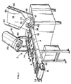
- Fig. 1 illustrates, in the form of a schematic perspective view, a packaging machine 2 for packaging substantially circular discoid products, such as effervescent tablets of various kinds, into tubes.
- the packaging machine 2 substantially comprises a conveyor 4 having a path switching device 6 and stop flaps 8, 10, a filling station 12, a tube magazine 14, and a cap feeder 16.
- the conveyor 4 as shown in Figs. 1 and 2 is a substantially horizontal belt conveyor that can be tensioned and adjusted by means of suitable attachments 20, 22 at a guide roller 18 and is connectible with a product-forming machine (not shown), such as a tablet-forming machine, or a circular feed table.
- a product-forming machine such as a tablet-forming machine, or a circular feed table.
- the path switching device 6 comprises preferably four downwardly open product channels 26 which, in Fig. 2, are indicated by means of the centre line of the respective channel.
- the path switching device 6 is pivotable about a vertical pivot pin 28 mounted approximately on the centre line of the path, at that end 30 of the path switching device 6 which faces the guide roller 18.
- the end 30 connects with the tablet-forming machine or with an inclined product feed path 32, of which but a part is shown in Fig. 2.
- the product channels 26 diverge from the infeed end 30 towards that end of the path switching device which faces away from the infeed end and at which a control means 34 in the form of a pneumatic or hydraulic piston and cylinder assembly is arranged.
- the path switching device 6 can be moved from a first end position in which four product strands 26A are formed on the conveyor, to a second end position in which four further products strands 26B are formed on the conveyor, resulting in a total of eight product strands uniformly distributed on the conveyor.
- the product channels 26 are spaced apart, at the discharge end of the path switching device 6, a distance such that there are formed, on the conveyor, product strands originating alternatingly from one end position 26A and the other end position 26B of the path switching device 6.
- the two stop flaps 8 and 10 are in the form of a beam which can be raised or lowered and is movable in the longitudinal direction of the conveyor.
- the beam is arranged transversely of the longitudinal direction of the conveyor and, in its lowered position, makes contact with the upper side 24 of the conveyor to prevent the passage of products. In its raised position, the beam allows the products to pass.
- the relative movements of these stop flaps are described hereinafter.
- the belt reverses at a second guide roller 36 in direct connection with the filling station 12 which is described below.
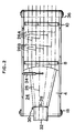
- Fig. 3 is a schematic sectional view of the filling station 12 which comprises a plurality of infeed sleeves 40, only one of which is shown in Figs. 3 and 4.
- Each tubular elongate infeed sleeve 40 is rotatably mounted at one end in an attachment 42, such that the longitudinal sleeve axis forms an angle of about 30° with the horizontal plane.
- the rotatably mounted end connects with the open end of a tube 44 which is supplied from the tube magazine 14 and whose longitudinal axis coincides, at the moment of filling, with the longitudinal axis of the infeed sleeve.
- the other sleeve end 46 which preferably is conically widened from the inner surface to the outer surface of the sleeve, connects with an inclined path 48 communicating the conveyor with the filling station 12 and thus permitting product flow to the tubes 44.
- the infeed sleeve 40 and a tube 44 supplied to said sleeve are rotated about the common longitudinal axis of rolls 56, 58, 60A, 60B (see Fig. 4) parallel to said sleeve and said tube. These rolls are preferably arranged at the corners of an isosceles triangle and are provided with friction rings 50, 52, 54A, 54B fixedly connected with the rolls and making contact with the outer surfaces of the infeed sleeve 40 and the tube 44.
- the two rolls 60A and 60B are so arranged directly below the sleeve 40 and the tube 44, respectively, that the longitudinal axes of the rolls coincide, the longitudinal axes of the sleeve and the tube being parallel and spaced apart in a vertical plane which is common to the axes of the rolls 60A, 60B.
- the friction rings 54A of the roll 60A carry the sleeve 40, and the friction rings 54B of the roll 60B carry the tube 44.
- the roll 60A can be adjusted to different diameters of the infeed sleeve 40.
- the roll 60B is movable from the position shown in Figs.
- All tubes to be filled are stored in and supplied from the tube magazine 14 which is shown in Figs. 1 and 5 and which substantially consists of an inclined bottom or supporting plate 62 with funnel-shaped lower walls 64, 66 which at their lowest point merge into a tube channel 68.
- the tubes 44 which are open at least at one end, are positioned with their closed end facing the supporting plate 62. When tubes are used which are open at both ends, it is immaterial how the tubes are positioned in the tube magazine, and one or the other of the tube ends may be positioned to face the supporting plate 62.
- a bridge-breaking member in the form of two plates 70, 72 extending outwardly from the supporting plate 62 and movable diagonally thereof between two end positions, the distance between these end positions preferably being selected on the basis of the diameter of the tubes 44.
- the tube channel 68 leads to a tube conveyor (not shown) intermittently supplying the tubes through the different stations of the packaging machine.
- the above-mentioned tube conveyor supplies each of the tubes to a checking station (not described in detail) at which it is checked that the correct number of tablets have been filled into the tube. If an error is indicated, the faulty tube is removed from the tube conveyor by means of a suitable device.
- the accepted tubes are finally fed to a capping or sealing station 44 (see Fig. 1) in which caps, plugs or other closure members are disposed in the tube opening to close the tube.
- the capping station 74 comprises a special cap feeder 16 (see Figs. 1, 6 and 7) and a cap holder and applicator movable between two end positions.
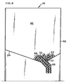
- the actual cap feeder 16 comprises a cylindrical casing 76 whose longitudinal axis forms an angle of about 30° with the horizontal plane.
- the upper part of the casing forms an upwardly open cap magazine 78 holding a number of randomly oriented caps (plugs, or the like).
- the lower part of the cap feeder 16 comprises two vertically spaced-apart, substantially circular plates 80, 82.
- the upper plate 80 is attached to the inner surface of the casing 76 and forms the bottom of the magazine 78.
- the plate has a recess 84 extending along the periphery of the plate 80 which also is inclined.
- a control means 92 such as a pneumatic or hydraulic piston and cylinder assembly, one leg 86 of said arm being movably attached to the plate 80 and connected, at a distance from its point of attachment 90, with the control means 92.
- the leg 86 is parallel to the lower side of the plate 80 and extended towards the recess 84.
- the other leg 88 of the arm which faces away from the point of attachment 90, is connected at right angles with the end of the leg 86, and extends along the casing towards the opening of the cap magazine 78.
- the movability of the arm about the point of attachment 90 is restricted to the peripheral length of the recess, such that the arm swings in pendulum fashion.
- the lower plate 82 is rotatably mounted at a distance from the upper plate 80 and is operated by a motor (not shown). Near the periphery of the plate 82, at least one finger 94 is mounted. The number of fingers, and the finger form required to give the desired technical effect, are chosen on the basis of the closure member at issue.
- the finger 94 orients the closure members in a given direction and supplies them to a channel 96 which preferably is divided into two part channels 98, 100 conducting the closure members to the above-mentioned cap holder and applicator.
- the tube is conducted to a labelling and/or packing station which need not be described in detail since such arrangements are well known in the art.
- the tube magazine 14 is filled with empty tubes 44, and if necessary regard must be paid at this moment to the tube orientation, while the cap magazine 78 is filled with caps or other closure members fitting the tubes 44 and the fingers 94.
- the packaging machine 2 which is linked up with the product-forming machine, is preferably started synchronously with the product-forming machine.
- the belt conveyor 4 starts, and at the same time tubes 44 are supplied by the tube feeder from the tube magazine 14, i.e. from the outlet end of the channel 68, to the filling station 12, and the cap feeder 16 supplies correctly oriented caps via the channel 96 to the cap holder and applicator.
- the tubes 44 are advanced intermittently, two at a time, until eight tubes parallel to one another are in the position shown in Fig. 4.
- the path switching device 6 assumes the first of the two available positions, the first stop flap 8 has been raised and allows tablets to pass, while the second stop flap 10 has been lowered and prevents the passage of tablets to the filling station 12.
- the tablets discharged from the product-forming machine are distributed on the belt or in two downwardly open channels to form the first four product strands 26A.
- Photodetectors mounted at the path switching device 6 detect when the correct preset number of tablets have passed the path switching device, and produce a signal which activates the control means 34 to move the path switching device 6 into the second one of the two available positions.
- the tablets discharged from the product-forming machine are distributed on the belt to form the other four product strands 26B.
- a second signal is produced to make the first stop flap 8 assume its lower position preventing the passage of tablets, and to make the other stop flap 10 assume its raised position allowing the tablets to pass.
- the eight tubes that have been filled at the same time are supplied two at a time past the checking station in which a transducer senses the level of tablets in each tube and, on the basis of this result, produces signals for the removal of an incorrectly filled tube from the tube conveyor, or for further conveyance of an accepted tube to the capping station 74.
- two empty tubes 44 are supplied to the filling station.
- the bridge-breaking members 70, 72 are moved a short distance in the diagonal direction of the supporting plate 62 (see Fig. 5) and then return directly to their respective starting positions. During this movement, a few tubes 44 are moved in some degree in the tube magazine 14, whereby any bridging effect in the magazine 14 is effectively prevented.
- Caps randomly stored in the cap magazine 78 of the capping station 74 are caused by the L-shaped arm 86, 88 (see Figs. 6 and 7) to drop onto the rotating lower plate 82 with the fingers 94.
- the fingers 94 now engage the caps which assume the desired orientation.
- the correctly oriented cap is disengaged from the finger 94 and, while retaining this orientation, is supplied down through the channel 96 or 100 to the cap holder and applicator which attaches a cap to each of two filled and accepted tubes supplied simultaneously to the capping station 74, and the open tube end is closed.
- the closed tubes are conducted to a labelling and/or packing station.
- the gentle and careful handling of the tablets that is achieved by using a conveyor which cooperates with a path switching device, and inclined rotary infeed sleeves having a conical opening makes it possible to fill a number of tubes, in the case here described eight tubes, far more quickly and with less total waste.
- the photodetectors arranged at the path switching device guarantee accurate counting of a desired number of tablets to be filled into each tube, by comparison of a predetermined number and the detected number, it being especially advantageous that the stop flaps are displaceable in the longitudinal direction of the conveyor.
- the packaging machine according to the present invention is highly efficient and adapted to the high-capacity tablet forming machines available on the market.
- the packaging machine according to the invention as described above constitutes a preferred embodiment, it will be appreciated that the expert can find other means and modifications to achieve the same technical effect.
- oval discoid products could be packed by suitable adaptation of the components of the packaging machine according to the invention.
- cap should be interpreted to comprise also other closure members, such as plugs, lids etc.
Landscapes
- Engineering & Computer Science (AREA)
- Mechanical Engineering (AREA)
- Basic Packing Technique (AREA)
- Container Filling Or Packaging Operations (AREA)
Claims (10)
- Verpackungsmaschine zum Verpacken von im wesentlichen scheibenförmigen Erzeugnissen in Röhrchen, die wenigstens eine Füllstation (12) mit wenigstens zwei parallelen Drehwalzen (56,58) umfaßt, die ein längliches Röhrchen (44) drehen, das vorzugsweise an einem Ende verschlossen ist, wobei sich das Ende unterhalb des anderen Endes des Röhrchens befindet, das offen ist; ein Röhrchenmagazin (14); sowie eine Vorrichtung, die der Füllstation (12) intermittierend Röhrchen aus dem Röhrchenmagazin (14) zuführt, gekennzeichnet durch eine Fördereinrichtung (4), die sich zwischen der Füllstation (12) und der Ausgabeseite einer erzeugnisherstellenden Maschine befindet und die Erzeugnisse der Füllstation (12) vorzugsweise mit einer konstanten Geschwindigkeit zuführt; eine Beschickungshülse (40), die so zwischen der Fördereinrichtung (4) und einem der Füllstation (12) zugeführten Röhrchen (44) angeordnet ist, daß ein Ende (46) der Hülse mit der Fördereinrichtung (4) in Verbindung steht, während das andere Hülsenende mit der Röhrchenöffnung in Verbindung steht; eine Drehwalze (60A), die sich unterhalb der Hülse (40) befindet und auf verschiedene Beschickungshülsendurchmesser eingestellt werden kann, wobei die Walze die Hülse (40) trägt; sowie eine Drehwalze (60B), die sich unterhalb des Röhrchens (44) befindet und zwischen zwei Endstellungen bewegt werden kann, wobei die zuletzt erwähnte Walze (60B) das Röhrchen (44) trägt und es in die oder aus der Füllposition bewegt.
- Verpackungsmaschine nach Anspruch 1, dadurch gekennzeichnet, daß die Beschickungshülse (40) drehbar angebracht ist; daß der Innendurchmesser der Hülse im wesentlichen dem Außendurchmesser des Erzeugnisses entspricht; und daß das Ende (46) der Hülse (40), das der Fördereinrichtung (4) zugewandt ist, konisch aufgeweitet ist, wodurch ein der Beschickungshülse (40) zugeführtes Erzeugnis, wenn der Rand des Erzeugnisses mit der Innenfläche der Hülse in Kontakt kommt, gedreht und angehoben wird, so daß eine im wesentlichen plane Fläche des Erzeugnisses am Übergang zwischen der Hülse (40) und dem Röhrchen (44) der Röhrchenöffnung zugewandt ist.
- Verpackungsmaschine nach Anspruch 2, dadurch gekennzeichnet, daß die Hülse (40) und das Röhrchen (44) so angeordnet sind, daß sie einen Winkel von ungefähr 30° zu der horizontalen Ebene bilden.
- Verpackungsmaschine nach einem der Ansprüche 1-3, gekennzeichnet durch eine Trenneinrichtung, die an dem Ende der Fördereinrichtung (4) vorhanden ist, das der Erzeugnisherstellungsmaschine zugewandt ist, um Erzeugnisauschuß von zum Verpacken geeigneten Erzeugnissen zu trennen.
- Verpackungsmaschine nach einem der Ansprüche 1-4, gekennzeichnet durch eine Wegumschaltvorrichtung (6), die direkt oberhalb der Fördereinrichtung (4) angeordnet ist und den Erzeugnisfluß so steuert, daß die Erzeugnisse auf der Oberseite (24) der Fördereinrichtung verteilt werden.
- Verpackungsmaschine nach Anspruch 5, dadurch gekennzeichnet, daß die Wegumschaltvorrichtung (6) um einen Drehzapfen (28) drehbar ist, der an dem Ende (30) der Wegumschaltvorrichtung (6) angeordnet ist, das der Erzeugnisherstellungsmaschine zugewandt ist, wobei sich der Drehzapfen im rechten Winkel zur Oberseite (24) der Fördereinrichtung befindet, und daß die Wegumschaltvorrichtung (6) eine Vielzahl von nach unten offenen Erzeugnisrinnen (26) umfaßt, die vom Beschickungsende (30) der Wegumschaltvorrichtung (6) in Richtung des Endes der Wegumschaltvorrichtung (6) auseinanderlaufen, das von dem Beschickungsende (30) abgewandt ist.
- Verpackungsmaschine nach einem der Ansprüche 1-6, gekennzeichnet durch zwei vertikal bewegliche Sperrklappen (8,10), die, in der Erzeugnisflußrichtung gesehen, hinter der Wegumschaltvorrichtung (6) quer zu der Fördereinrichtung (4) angeordnet sind und in der Längsrichtung der Fördereinrichtung verschiebbar sind, wobei die Sperrklappen, wenn sie ihren angehobenen Zustand einnehmen, den Durchlauf von transportierten Erzeugnissen ermöglichen, und wenn sie ihren abgesenkten Zustand einnehmen, mit der Oberseite (24) der Fördereinrichtung in Kontakt kommen und so den Durchlauf transportierter Erzeugnisse verhindern.
- Verpackungsmaschine nach einem der Ansprüche 1-7, gekennzeichnet durch Wandler, die an der Wegumschaltvorrichtung (6) angeordnet sind, und in Reaktion auf das Ergebnis eines Vergleichs einer vorgegebenen gewünschten Anzahl von Erzeugniseinheiten mit einer erfaßten Anzahl von Erzeugniseinheiten Signale zur Steuerung der Sperrklappen (8,10) erzeugen.
- Verpackungsmaschine nach einem der Ansprüche 1-8, gekennzeichnet durch wenigstens ein brückenbrechendes Element (70,72), das zwischen zwei Endstellungen bewegt werden kann und an einer Ausgaberinne (68) des Röhrchenmagazins (14) angeordnet ist, wobei das brückenbrechende Element eine Brückenbildung von Röhrchen (44) in dem Röhrchenmagazin (14) verhindert, wodurch Abschaltung und/oder falsche Anzeige verhindert werden.
- Verpackungsmaschine nach einem der Ansprüche 1-9, gekennzeichnet durch eine Prüfstation, die, in der Röhrchenzuführrichtung gesehen, zwischen der Zuführstation (12) und einer Verschlußstation (74) angeordnet ist, wobei die Prüfstation einen Wandler umfaßt, der in das gefüllte Röhrchen eingeführt werden kann, um die Füllhöhe des Röhrchens zu überprüfen, sowie eine Auswerfeinrichtung zur Entfernung eines zurückgewiesenen Röhrchens aus der Röhrchenfördereinrichtung.
Applications Claiming Priority (2)
| Application Number | Priority Date | Filing Date | Title |
|---|---|---|---|
| SE8902552A SE462907B (sv) | 1989-07-14 | 1989-07-14 | Maskin foer tablett-fyllning i tubformade foerpackningar |
| SE8902552 | 1989-07-14 |
Publications (2)
| Publication Number | Publication Date |
|---|---|
| EP0414652A1 EP0414652A1 (de) | 1991-02-27 |
| EP0414652B1 true EP0414652B1 (de) | 1994-12-14 |
Family
ID=20376558
Family Applications (1)
| Application Number | Title | Priority Date | Filing Date |
|---|---|---|---|
| EP90850267A Expired - Lifetime EP0414652B1 (de) | 1989-07-14 | 1990-07-10 | Verpackungsmaschine zum Füllen von Röhrchen mit Tabletten oder dgl. |
Country Status (5)
| Country | Link |
|---|---|
| EP (1) | EP0414652B1 (de) |
| JP (1) | JPH03111205A (de) |
| AT (1) | ATE115488T1 (de) |
| DE (1) | DE69015054T2 (de) |
| SE (1) | SE462907B (de) |
Families Citing this family (3)
| Publication number | Priority date | Publication date | Assignee | Title |
|---|---|---|---|---|
| DE4406089C2 (de) * | 1994-02-24 | 1996-04-11 | Lingenfelder Oli Spezialanlage | Vorrichtung zum Abfüllen von Tabletten oder dergleichen in Tablettenröhrchen |
| JP4318766B2 (ja) * | 1997-06-17 | 2009-08-26 | 株式会社湯山製作所 | 錠剤充填装置 |
| EP1857365A1 (de) * | 1998-10-08 | 2007-11-21 | Yuyama Mfg. Co., Ltd. | Tablettenverpackungsvorrichtung |
Family Cites Families (5)
| Publication number | Priority date | Publication date | Assignee | Title |
|---|---|---|---|---|
| FR662565A (fr) * | 1927-10-19 | 1929-08-08 | Ig Farbenindustrie Ag | Procédé permettant de mettre des articles ou matières solides dans des récipients et appareils pour la mise en pratique de ce procédé |
| DE1277739B (de) * | 1966-06-23 | 1968-09-12 | Asta Werke Ag Chem Fab | Vorrichtung zum Abfuellen von Dragees in aufrechtstehende Roehrchen od. dgl. |
| JPS50133089A (de) * | 1974-03-07 | 1975-10-21 | ||
| SE406065B (sv) * | 1977-05-12 | 1979-01-22 | Fransson Gosta Ingvar | Maskin for fyllning av tabletter i ror |
| JPS5529474A (en) * | 1978-08-23 | 1980-03-01 | Tokyo Shibaura Electric Co | Aligning packing method of filamentous body |
-
1989
- 1989-07-14 SE SE8902552A patent/SE462907B/sv not_active IP Right Cessation
-
1990
- 1990-07-10 EP EP90850267A patent/EP0414652B1/de not_active Expired - Lifetime
- 1990-07-10 AT AT90850267T patent/ATE115488T1/de active
- 1990-07-10 DE DE69015054T patent/DE69015054T2/de not_active Expired - Lifetime
- 1990-07-13 JP JP2186960A patent/JPH03111205A/ja active Pending
Also Published As
| Publication number | Publication date |
|---|---|
| EP0414652A1 (de) | 1991-02-27 |
| DE69015054T2 (de) | 1995-07-20 |
| ATE115488T1 (de) | 1994-12-15 |
| SE462907B (sv) | 1990-09-17 |
| JPH03111205A (ja) | 1991-05-13 |
| DE69015054D1 (de) | 1995-01-26 |
| SE8902552D0 (sv) | 1989-07-14 |
Similar Documents
| Publication | Publication Date | Title |
|---|---|---|
| EP1380510B1 (de) | Verfahren und Vorrichtung zum Selektieren und Zuführen von Artikeln | |
| US7878366B2 (en) | Unit for filling containers with products, in particular, pharmaceutical products | |
| US4677283A (en) | Device for counting and loading small items into containers | |
| US6497342B2 (en) | Medicine feeder | |
| US4596107A (en) | Reject mechanism for bottle capping machine | |
| US6119440A (en) | Single level multiple product filler wheel | |
| CA1066241A (en) | Chip packing apparatus and method | |
| WO1997011883A1 (en) | A packaging machine and a method for packaging units in portions | |
| CA1304318C (en) | Apparatus for erecting and lining-up moulded parts | |
| US5383322A (en) | Single pack reject mechanism for cigarette packaging machine and method | |
| US5235796A (en) | Method and apparatus for packaging articles | |
| US5263302A (en) | Packing device | |
| CN110369314B (zh) | 瓶装药防倾倒式检重剔废装置 | |
| US5802820A (en) | Apparatus for obtaining the uniform distribution of a cohesionless substance contained within a bag | |
| EP0414652A1 (de) | Verpackungsmaschine zum Füllen von Röhrchen mit Tabletten oder dgl. | |
| CN113101221A (zh) | 一种胶囊填充灌装一体机 | |
| US2319900A (en) | Apparatus for packing foodstuffs in cans | |
| US4250691A (en) | Feeding apparatus | |
| CN119147712B (zh) | 药片测量装置 | |
| CN210526901U (zh) | 一种药品包装机 | |
| ITBO980277A1 (it) | Gruppo orientatore di coperchi o fondelli per capsule medicinali ed un ita' alimentatrice ed orientatrice relativa a tale gruppo. | |
| CN214327079U (zh) | 一种自动旋盖压盖装置 | |
| JP2683891B2 (ja) | 散薬自動分包機 | |
| WO1986007040A1 (en) | Alignment and orientation feeder | |
| JP3419494B2 (ja) | 缶蓋の袋詰装置 |
Legal Events
| Date | Code | Title | Description |
|---|---|---|---|
| PUAI | Public reference made under article 153(3) epc to a published international application that has entered the european phase |
Free format text: ORIGINAL CODE: 0009012 |
|
| AK | Designated contracting states |
Kind code of ref document: A1 Designated state(s): AT BE CH DE ES FR GB IT LI NL |
|
| 17P | Request for examination filed |
Effective date: 19910808 |
|
| 17Q | First examination report despatched |
Effective date: 19930716 |
|
| RAP1 | Party data changed (applicant data changed or rights of an application transferred) |
Owner name: GORDIC AB |
|
| GRAA | (expected) grant |
Free format text: ORIGINAL CODE: 0009210 |
|
| AK | Designated contracting states |
Kind code of ref document: B1 Designated state(s): AT BE CH DE ES FR GB IT LI NL |
|
| PG25 | Lapsed in a contracting state [announced via postgrant information from national office to epo] |
Ref country code: IT Free format text: LAPSE BECAUSE OF FAILURE TO SUBMIT A TRANSLATION OF THE DESCRIPTION OR TO PAY THE FEE WITHIN THE PRESCRIBED TIME-LIMIT;WARNING: LAPSES OF ITALIAN PATENTS WITH EFFECTIVE DATE BEFORE 2007 MAY HAVE OCCURRED AT ANY TIME BEFORE 2007. THE CORRECT EFFECTIVE DATE MAY BE DIFFERENT FROM THE ONE RECORDED. Effective date: 19941214 Ref country code: NL Effective date: 19941214 Ref country code: LI Effective date: 19941214 Ref country code: AT Effective date: 19941214 Ref country code: BE Effective date: 19941214 Ref country code: CH Effective date: 19941214 Ref country code: ES Free format text: THE PATENT HAS BEEN ANNULLED BY A DECISION OF A NATIONAL AUTHORITY Effective date: 19941214 |
|
| REF | Corresponds to: |
Ref document number: 115488 Country of ref document: AT Date of ref document: 19941215 Kind code of ref document: T |
|
| REF | Corresponds to: |
Ref document number: 69015054 Country of ref document: DE Date of ref document: 19950126 |
|
| ET | Fr: translation filed | ||
| EL | Fr: translation of claims filed |
Free format text: BO 95/04: ANNULATION |
|
| ET | Fr: translation filed | ||
| REG | Reference to a national code |
Ref country code: CH Ref legal event code: PL |
|
| NLV1 | Nl: lapsed or annulled due to failure to fulfill the requirements of art. 29p and 29m of the patents act | ||
| PLBE | No opposition filed within time limit |
Free format text: ORIGINAL CODE: 0009261 |
|
| STAA | Information on the status of an ep patent application or granted ep patent |
Free format text: STATUS: NO OPPOSITION FILED WITHIN TIME LIMIT |
|
| 26N | No opposition filed | ||
| PGFP | Annual fee paid to national office [announced via postgrant information from national office to epo] |
Ref country code: GB Payment date: 20000516 Year of fee payment: 11 |
|
| PGFP | Annual fee paid to national office [announced via postgrant information from national office to epo] |
Ref country code: FR Payment date: 20000712 Year of fee payment: 11 |
|
| PG25 | Lapsed in a contracting state [announced via postgrant information from national office to epo] |
Ref country code: GB Free format text: LAPSE BECAUSE OF NON-PAYMENT OF DUE FEES Effective date: 20010710 |
|
| GBPC | Gb: european patent ceased through non-payment of renewal fee |
Effective date: 20010710 |
|
| PG25 | Lapsed in a contracting state [announced via postgrant information from national office to epo] |
Ref country code: FR Free format text: LAPSE BECAUSE OF NON-PAYMENT OF DUE FEES Effective date: 20020329 |
|
| REG | Reference to a national code |
Ref country code: FR Ref legal event code: ST |
|
| REG | Reference to a national code |
Ref country code: GB Ref legal event code: 728V |
|
| REG | Reference to a national code |
Ref country code: GB Ref legal event code: 7281 |
|
| PGFP | Annual fee paid to national office [announced via postgrant information from national office to epo] |
Ref country code: DE Payment date: 20090728 Year of fee payment: 20 |
|
| PG25 | Lapsed in a contracting state [announced via postgrant information from national office to epo] |
Ref country code: DE Free format text: LAPSE BECAUSE OF EXPIRATION OF PROTECTION Effective date: 20100710 |