EP0414982A1 - Sonnenkompass und Zeitanzeigeeinrichtung - Google Patents
Sonnenkompass und Zeitanzeigeeinrichtung Download PDFInfo
- Publication number
- EP0414982A1 EP0414982A1 EP89810654A EP89810654A EP0414982A1 EP 0414982 A1 EP0414982 A1 EP 0414982A1 EP 89810654 A EP89810654 A EP 89810654A EP 89810654 A EP89810654 A EP 89810654A EP 0414982 A1 EP0414982 A1 EP 0414982A1
- Authority
- EP
- European Patent Office
- Prior art keywords
- disc
- compass device
- ring
- solar compass
- disposed
- Prior art date
- Legal status (The legal status is an assumption and is not a legal conclusion. Google has not performed a legal analysis and makes no representation as to the accuracy of the status listed.)
- Withdrawn
Links
- 238000006073 displacement reaction Methods 0.000 claims abstract description 3
- 230000002093 peripheral effect Effects 0.000 claims description 2
- 239000012780 transparent material Substances 0.000 claims description 2
- 206010021033 Hypomenorrhoea Diseases 0.000 claims 1
- 230000004048 modification Effects 0.000 description 4
- 238000012986 modification Methods 0.000 description 4
- 230000008447 perception Effects 0.000 description 3
- 229920003023 plastic Polymers 0.000 description 3
- 239000011521 glass Substances 0.000 description 2
- 239000000463 material Substances 0.000 description 2
- 238000004040 coloring Methods 0.000 description 1
- 230000007613 environmental effect Effects 0.000 description 1
- 238000004519 manufacturing process Methods 0.000 description 1
- 239000002184 metal Substances 0.000 description 1
- 239000007769 metal material Substances 0.000 description 1
- 239000002689 soil Substances 0.000 description 1
Images

Classifications
-
- G—PHYSICS
- G01—MEASURING; TESTING
- G01C—MEASURING DISTANCES, LEVELS OR BEARINGS; SURVEYING; NAVIGATION; GYROSCOPIC INSTRUMENTS; PHOTOGRAMMETRY OR VIDEOGRAMMETRY
- G01C17/00—Compasses; Devices for ascertaining true or magnetic north for navigation or surveying purposes
- G01C17/34—Sun- or astro-compasses
Definitions
- the present invention relates to a novel compass device wherein at least two flat disc members are secured to one another with one of the members having spaced apart markings indicative of time and disposed in a counterclockwise direction and the second member having an indicating means aligned on a radius between a center point relative to the ring so that the north pole can be detected by orienting a 12 o'clock marking on the ring with the sun. Simultaneously the time of day can also be ascertained in major cities of the world as the compass device may also be used as a time indicator device.
- the device is formed of two small circular discs secured in flat side-by-side relationship at the center thereof with the center of a disc indicating the north pole.
- compasses Another disadvantage of such compasses is that the needle is delicatelly supported and protected by a glass top, if the glass is broken, by dropping the compass on the ground or if a person carrying the compass falls, the needle will also be broken. Still further, such compasses are usually bulky as they require a predetermined thickness in its casing whereby to support needles elevated therein. They also indicate the direction of the magnetic north instead of the geographic north, which can be substantially different.
- Another feature of the present invention is to provide a solar compass device which is constructed of flat discs of non-metallic material and which may be easily carried in the pocket of an article.
- Another feature of the present invention is to provide a compass and time indicator device which indicates the direction of the north pole by the use of the sun and the approximate time of day.
- Another feature of the present invention is to provide a compass and time indicator device which is capable of providing an indication of the time of day in many major cities around the globe and which further indicates the date line and the direction of rotation of the earth as viewed from the north pole.
- Another feature of the present invention is to provide a solar compass device which can be utilized as a teaching aid to teach a person how he can orient himself, the position of the country he resides in relative to the sun and other countries, an explanation of the cause of night and day including the relationship between movement of the earth and time.
- Another feature of the present invention is to provide a compass and time indicator device which is easy and economical to manufacture.
- the present invention provides a solar compass device comprising a first member having spaced apart markings indicative of time and disposed in a counterclockwise direction in a circular ring pattern thereon.
- a second member is rotatably displaceable with respect to the first member to permit rotational displacement between the first and second members with said members disposed in substantially parallel planes.
- Indicating means is provided on the second member and aligned on a radius between a center point relative to the ring and the ring.
- the first member when oriented with one of the markings which is representative of 12 o'clock and aligned substantially in the direction of the sun and the indicating means aligned with a marking indicative of approximately the time of day, the indicating means automatically indicates the approximate direction of the north pole.
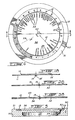
- the device comprises a first member, herein a flat plastic disc 11 having spaced apart markings 12 indicative of time and disposed in a counterclockwise direction in a circular ring pattern 13.
- a second member or disc 14 is rotatably displaceable with respect to the first member 11 by a connection 15 located at a center point relative to the ring 11.
- the second member 14 is of a smaller diameter and has its outer periphery 14′ located adjacent the inner edge of the ring portion 13 of the first member 11.
- Indicating means 16 as herein shown in the form of a compass symbol is oriented with its north/south pole axis 17 aligned on a radius between a center axis 18 or the center connection 15 and the ring portion 13.
- the markings 12 are equidistantly spaced numbers disposed about the ring 13 and contain numbers from 1 to 24 inclusively, which are the number of hours in a day and are disposed in a counterclockwise direction about the ring, as previously mentioned. Further markings 12′ may be provided therebetween to indicate various fractions of the hour markings. As also herein shown, the twelve hour marking 18 is readily identifiable from the other numbers and this is done by replacing the number by a colored dot. The 13 hour marking 12′ is utilized by the marking 18 during daylight savings time.
- the north end portion 16 ⁇ of the indicator 16 points approximately in the direction of the north pole.
- the north pole has been indicated with respect to the location of the sun and the time of day.
- the ring portion 13 has portions thereof of different shading or coloring whereby to indicate the periods of daytime. For example, portion 19 indicates the nightime period, portion 20 indicates the daytime period, portion 21 indicates the dawn period and portion 22 indicates the dusk period. Therefore, a person quickly receives a perception of where he resides in time in a full day's cycle. Also, the dusk and dawn periods indicate to him the variations in the daylight period from the longest day of the year to the shortest day of the year and this is done in approximation.
- the device 10′ comprises two discs, a bottom disc 30 which contains the indicating markings 16 disposed in the same fashion as did the top disc in Figure 1a, and a top disc 31 which is formed of transparent plastic material.
- the ring portion 13 as herein shown is provided on the top disc. Accordingly, the discs are herein shown in an inverted configuration but the operation of this compass 10′ is the same as compass 10 of Figure 1a as both discs are rotatably connected at the center thereof by the center connection 15.
- the first member 33 is the member comprising the ring portion 13 with the hour markings 12 thereon.
- the ring portion 13 is an opaque portion and also having the nightime and daytime zones indicated thereon and its center portion 33′ is formed of transparent material.
- the second member 34 is a strip-like member secured by the connection 15 and is herein shown as formed of transparent plastic material. This member 34 is herein shown as captive between the first member 33 and third member 32 and extending thereacross.
- This strip-like member 34 also has an outer end engaging portion 36 extending beyond the outer circumference 37 of both the first and third disc members and this is utilized for grasping between the fingers to displace the second member on its pivot point or pivot connection 15.
- An arrow 38 constitutes the indicating means and is located on a radius centrally of the longitudinal axis of the strip-like member 34. As herein shown, both the first and third discs are of substantially the same size.
- the third disc is further provided with a set of markings 38 representative of major cities of the world and disposed substantially on radii axes and adjacent the inner peripheral portion 13′ of the ring 13. These international city markings are positioned relative to their geographical locations with respect to the north pole.
- An international date line marking 39 is also positioned relative to the city markings and the north pole to give the perception of the user of his location in time and space relative to the earth when the disc is viewed as it represents the earth from a stationary object looking at the north pole of the earth.
- the arrow 40 indicates the direction of rotation of the earth.
- the device comprises a large base member 50 which has a flat top surface 51.
- the ring member 13 is herein shown as an independent member rotatably secured in a cavity 52 or on top of the base and having a circumferential gear 53 thereunder engaged with the drive gear train 54 of a clock mechanism 55 located within the base member 50. With this particular embodiment, the ring member 13 is rotated in a clockwise direction the same as would the needles of a clock.
- the indicator means points to the north.
- the center disc 56 is provided with the markings 38 thereon and there is no need for a central pivot connection as this disc is also held in the cavity 52 in the top wall of the base 50.
Landscapes
- Physics & Mathematics (AREA)
- Engineering & Computer Science (AREA)
- Radar, Positioning & Navigation (AREA)
- Remote Sensing (AREA)
- Astronomy & Astrophysics (AREA)
- General Physics & Mathematics (AREA)
- Electromechanical Clocks (AREA)
Applications Claiming Priority (1)
| Application Number | Priority Date | Filing Date | Title |
|---|---|---|---|
| US07/180,206 US4899451A (en) | 1988-04-11 | 1988-04-11 | Solar compass and time indicator device |
Publications (1)
| Publication Number | Publication Date |
|---|---|
| EP0414982A1 true EP0414982A1 (de) | 1991-03-06 |
Family
ID=22659612
Family Applications (1)
| Application Number | Title | Priority Date | Filing Date |
|---|---|---|---|
| EP89810654A Withdrawn EP0414982A1 (de) | 1988-04-11 | 1989-09-01 | Sonnenkompass und Zeitanzeigeeinrichtung |
Country Status (2)
| Country | Link |
|---|---|
| US (1) | US4899451A (de) |
| EP (1) | EP0414982A1 (de) |
Cited By (1)
| Publication number | Priority date | Publication date | Assignee | Title |
|---|---|---|---|---|
| WO1998010247A1 (en) * | 1996-09-06 | 1998-03-12 | Aspen Kjell | A moon compass |
Families Citing this family (9)
| Publication number | Priority date | Publication date | Assignee | Title |
|---|---|---|---|---|
| CH680632B5 (de) * | 1990-04-18 | 1993-04-15 | Longines Montres Comp D | |
| GB9119422D0 (en) * | 1991-09-11 | 1991-10-23 | Waltho Barry S | A direction indicator |
| US5425178A (en) * | 1994-06-03 | 1995-06-20 | Steele; Felix G. | Solar compass |
| US7555840B2 (en) * | 2007-08-17 | 2009-07-07 | The Trustees Of Columbia University In The City Of New York | Omni-directional lens in sundials and solar compasses |
| CN102455181A (zh) * | 2010-10-21 | 2012-05-16 | 上海三旗通信科技股份有限公司 | 太阳指南针 |
| GB2488806A (en) * | 2011-03-09 | 2012-09-12 | Instro Prec Ltd | Digital solar compass |
| ITRM20120664A1 (it) | 2012-12-27 | 2014-06-28 | Enea Agenzia Naz Per Le Nuo Ve Tecnologie | Bussola solare elettronica ad alta precisione. |
| US20160076887A1 (en) * | 2014-09-12 | 2016-03-17 | Magpul Industries Corp | Sundial compass |
| CN111272160B (zh) * | 2020-03-27 | 2020-11-03 | 义乌台维电子科技有限公司 | 一种透明底盘指南针用精度自动测试装置 |
Citations (5)
| Publication number | Priority date | Publication date | Assignee | Title |
|---|---|---|---|---|
| DE626749C (de) * | 1934-03-21 | 1936-03-02 | Hellmut Pohle Dipl Ing | Sonnenkompass |
| US3243881A (en) * | 1963-05-09 | 1966-04-05 | William J Brink | Navigational instrument |
| US3545199A (en) * | 1969-05-16 | 1970-12-08 | William Rice Jr | Combined timepiece and compass |
| GB2191579A (en) * | 1986-06-13 | 1987-12-16 | Paul Dominic Anderson | Sun compasses |
| DE3631513A1 (de) * | 1986-09-12 | 1988-03-24 | Ulrich Hamann | Sonnenkompass |
Family Cites Families (6)
| Publication number | Priority date | Publication date | Assignee | Title |
|---|---|---|---|---|
| US963597A (en) * | 1909-08-16 | 1910-07-05 | Allan Henderson Lessells | Non-magnetic compass. |
| US1258160A (en) * | 1916-09-25 | 1918-03-05 | Mabel H Slater | Sun-dial and compass. |
| US1587413A (en) * | 1924-12-03 | 1926-06-01 | Pond John | Time-indicating device |
| US2408571A (en) * | 1944-04-24 | 1946-10-01 | Hubert L Mitchell | Navigational computing instrument |
| US2532324A (en) * | 1948-11-05 | 1950-12-05 | Harry B Milligan | Star watch |
| US4512085A (en) * | 1982-11-22 | 1985-04-23 | Liddell Olin E | Method of and apparatus for telling time at night |
-
1988
- 1988-04-11 US US07/180,206 patent/US4899451A/en not_active Expired - Lifetime
-
1989
- 1989-09-01 EP EP89810654A patent/EP0414982A1/de not_active Withdrawn
Patent Citations (5)
| Publication number | Priority date | Publication date | Assignee | Title |
|---|---|---|---|---|
| DE626749C (de) * | 1934-03-21 | 1936-03-02 | Hellmut Pohle Dipl Ing | Sonnenkompass |
| US3243881A (en) * | 1963-05-09 | 1966-04-05 | William J Brink | Navigational instrument |
| US3545199A (en) * | 1969-05-16 | 1970-12-08 | William Rice Jr | Combined timepiece and compass |
| GB2191579A (en) * | 1986-06-13 | 1987-12-16 | Paul Dominic Anderson | Sun compasses |
| DE3631513A1 (de) * | 1986-09-12 | 1988-03-24 | Ulrich Hamann | Sonnenkompass |
Cited By (1)
| Publication number | Priority date | Publication date | Assignee | Title |
|---|---|---|---|---|
| WO1998010247A1 (en) * | 1996-09-06 | 1998-03-12 | Aspen Kjell | A moon compass |
Also Published As
| Publication number | Publication date |
|---|---|
| US4899451A (en) | 1990-02-13 |
Similar Documents
| Publication | Publication Date | Title |
|---|---|---|
| CN1086812C (zh) | 带有可从月球看到的地球部分的显示的时计 | |
| US5197043A (en) | Night and day earth clock calendar | |
| US4847819A (en) | Universal clock having means for indicating zonal time in other global time zones | |
| US4899451A (en) | Solar compass and time indicator device | |
| US5917778A (en) | Geographical chronological device | |
| US4502789A (en) | Clock | |
| JPH0862352A (ja) | 携帯時計 | |
| US6744695B2 (en) | Planisphere watch | |
| US4551027A (en) | Device for determining time of sunrise and sunset | |
| JPS5984180A (ja) | 世界時計 | |
| US2721442A (en) | Global clock | |
| CA1296519C (en) | Solar compass and time indicator device | |
| JPH0481092U (de) | ||
| US3360196A (en) | Time and space chart | |
| CA1210596A (en) | Method of and apparatus for telling time at night | |
| JPH03125990A (ja) | 太陽コンパス及び時刻表示装置 | |
| US4985876A (en) | Global clock apparatus | |
| US5365498A (en) | Sundial-like timepiece | |
| KR20100040194A (ko) | 천체운동 학습판 | |
| US2188041A (en) | Astronomical device | |
| US2696053A (en) | Astronomical locator | |
| GB2191579A (en) | Sun compasses | |
| CN2322166Y (zh) | 时刻盘转动式环球钟 | |
| JPH0648535Y2 (ja) | 昼夜分界環付きの地球儀 | |
| CN2294485Y (zh) | 一种世界时间换算器 |
Legal Events
| Date | Code | Title | Description |
|---|---|---|---|
| PUAI | Public reference made under article 153(3) epc to a published international application that has entered the european phase |
Free format text: ORIGINAL CODE: 0009012 |
|
| AK | Designated contracting states |
Kind code of ref document: A1 Designated state(s): AT BE CH DE ES FR GB GR IT LI LU NL SE |
|
| 17P | Request for examination filed |
Effective date: 19910905 |
|
| 17Q | First examination report despatched |
Effective date: 19921020 |
|
| STAA | Information on the status of an ep patent application or granted ep patent |
Free format text: STATUS: THE APPLICATION IS DEEMED TO BE WITHDRAWN |
|
| 18D | Application deemed to be withdrawn |
Effective date: 19930501 |