EP0415112A2 - Procédé d'interconnexion (cross-connect) pour signaux STM-1 d'une hiérarchie multiplex synchrone et numérique - Google Patents
Procédé d'interconnexion (cross-connect) pour signaux STM-1 d'une hiérarchie multiplex synchrone et numérique Download PDFInfo
- Publication number
- EP0415112A2 EP0415112A2 EP90114796A EP90114796A EP0415112A2 EP 0415112 A2 EP0415112 A2 EP 0415112A2 EP 90114796 A EP90114796 A EP 90114796A EP 90114796 A EP90114796 A EP 90114796A EP 0415112 A2 EP0415112 A2 EP 0415112A2
- Authority
- EP
- European Patent Office
- Prior art keywords
- switching matrix
- ptr
- signals
- tug
- virtual container
- Prior art date
- Legal status (The legal status is an assumption and is not a legal conclusion. Google has not performed a legal analysis and makes no representation as to the accuracy of the status listed.)
- Granted
Links
- 238000000034 method Methods 0.000 title claims abstract description 30
- 239000011159 matrix material Substances 0.000 claims abstract description 67
- 230000001360 synchronised effect Effects 0.000 claims abstract description 17
- 230000006978 adaptation Effects 0.000 claims abstract description 16
- 230000008569 process Effects 0.000 claims abstract description 4
- 230000008878 coupling Effects 0.000 claims description 8
- 238000010168 coupling process Methods 0.000 claims description 8
- 238000005859 coupling reaction Methods 0.000 claims description 8
- 238000011156 evaluation Methods 0.000 claims 2
- 102100030511 Stanniocalcin-1 Human genes 0.000 claims 1
- 101710142157 Stanniocalcin-1 Proteins 0.000 claims 1
- 238000000605 extraction Methods 0.000 claims 1
- 238000012544 monitoring process Methods 0.000 claims 1
- 230000001960 triggered effect Effects 0.000 claims 1
- 230000006870 function Effects 0.000 description 7
- 230000005540 biological transmission Effects 0.000 description 6
- 238000003780 insertion Methods 0.000 description 6
- 230000037431 insertion Effects 0.000 description 6
- 239000000203 mixture Substances 0.000 description 5
- 238000010276 construction Methods 0.000 description 2
- 230000015572 biosynthetic process Effects 0.000 description 1
- 230000015654 memory Effects 0.000 description 1
- 230000002123 temporal effect Effects 0.000 description 1
- 230000007704 transition Effects 0.000 description 1
- 238000011144 upstream manufacturing Methods 0.000 description 1
Images




Classifications
-
- H—ELECTRICITY
- H04—ELECTRIC COMMUNICATION TECHNIQUE
- H04J—MULTIPLEX COMMUNICATION
- H04J3/00—Time-division multiplex systems
- H04J3/02—Details
- H04J3/08—Intermediate station arrangements, e.g. for branching, for tapping-off
-
- H—ELECTRICITY
- H04—ELECTRIC COMMUNICATION TECHNIQUE
- H04J—MULTIPLEX COMMUNICATION
- H04J3/00—Time-division multiplex systems
- H04J3/16—Time-division multiplex systems in which the time allocation to individual channels within a transmission cycle is variable, e.g. to accommodate varying complexity of signals, to vary number of channels transmitted
- H04J3/1605—Fixed allocated frame structures
- H04J3/1611—Synchronous digital hierarchy [SDH] or SONET
-
- H—ELECTRICITY
- H04—ELECTRIC COMMUNICATION TECHNIQUE
- H04J—MULTIPLEX COMMUNICATION
- H04J2203/00—Aspects of optical multiplex systems other than those covered by H04J14/05 and H04J14/07
- H04J2203/0001—Provisions for broadband connections in integrated services digital network using frames of the Optical Transport Network [OTN] or using synchronous transfer mode [STM], e.g. SONET, SDH
- H04J2203/0028—Local loop
- H04J2203/0039—Topology
- H04J2203/0041—Star, e.g. cross-connect, concentrator, subscriber group equipment, remote electronics
Definitions
- the invention relates to a method according to the preamble of claim 1.
- German patent application DE 35 11 352 A1 discloses a method and a coupling device for distributing plesiochronous broadband digital signals, in which these signals, controlled by a central clock, are converted into intermediate digital signals containing plugs and, after passing through a switching matrix, converted back into plesiochronous Broadband digital signals are converted back.
- the object of the invention is to provide a method with which data blocks of different multiplex structures can be converted into cross-connect data blocks.
- a virtual container group consists of one or more Virtual containers, subsystem units or subsystem unit groups.
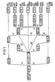
- Figure 1 shows the multiplex structure according to the CCITT recommendation G.709.
- Administration Unit Administration Unit
- C container H digital signal
- STM synchronous transport module STM synchronous transport module
- TU subsystem unit Tributary Unit
- TUG subsystem unit group Tributary Unit Group
- the digital signals to be transmitted are inserted at the input node to the synchronous network by means of positive plugs in gontainers Cn.
- Each container is supplemented by adding a path overhaed POH to a virtual container VC-n, which are transmitted periodically.
- the first byte of a virtual container is specified by a pointer (pointer) PTR, the temporal position of which is defined in the transmission frame is.
- the virtual container serves as a higher hierarchical level.
- a virtual container VC-n forms a subsystem unit TU-n with the pointer assigned to it.
- Figure 1 shows the different ways in which multiplexing or demultiplexing is possible.
- sixty-four H12 signals can be inserted into the virtual container VC-4 either directly via the subsystem unit group TUG-22 or indirectly via the virtual container VC-31 and the formation of the subsystem unit TU-31.
- FIG. 3.13 / G.709 show, the subsystem units TU-12 and TU-22 are divided into superframes of 500 ⁇ s each. One contains four frames with a period of 125 ⁇ s.
- the first byte V1, V2, V3 and V4 of each frame is specified in the CCITT recommendation G.709.
- Bytes V1 are always in the first line of an overframe.
- the path frame header POH of the virtual container VC-31 or the virtual container VC-4 defines the superframe by a byte H4.
- the first line is identified by a byte J1.
- the path frame header POH of the virtual container VC-4 determines the position of the bytes Un, while when inserted via the virtual container VC-31 the path frame header VC-31 POH of the virtual container VC -31 determines the order of the bytes Vn.
- the same multiplexing devices are required at both ends of a connection if one does not insert a converter into the connection, for example from the sixteen subsystem units groups TUG-22 of one way forms four subsystem units TU-31 of the other way.
- This also applies to the transmission of a maximum of sixteen 8448 kbit / s signals or a mixture of 8448 and 2048 kbit / s signals (H12 signals).
- the same applies to the construction of the virtual container VC-4 over twenty-one subsystem unit groups TUG-21 or three subsystem units TU-31 for the 1.5 Mbit / s hierarchy in the upper part of FIG. 1.
- 34368 kbit / s signals (H21 signals) can only be inserted on the way via the virtual container VC-31 and the subsystem unit TU-31.
- the arrangement according to FIG. 3 from ETSI differs from that according to FIG. 1 in that the path from the subsystem unit group TUG-22 via the virtual container VC-31 and the subsystem unit TU-31 to the virtual container VC-4 is omitted.
- VC-4 Virtual Containers with a mixture of n x 4 subsystem unit groups TUG-22 and 4 - n subsystem units TU-31.
- Four subsystem unit groups TUG-22 form a subsystem unit group TUG-31. In contrast to a TU-31 subsystem unit, this does not have its own pointer or a common path frame header.
- the pointers belonging to the TU-12 or TU-22 subsystem units belonging to a subsystem unit group TUG-31 are regularly arranged. Their position is determined by the path frame header VC-4 POH of the virtual container VC-4. With such a mixture, the first four columns of a container C-4 contain the TU-31 pointer or a fixed pattern (plug).
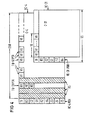
- FIG. 4 shows an example in which two subsystem unit groups TUG-31, a subsystem unit TU-31 and a third subsystem unit group TUG-31 are inserted in columns in a virtual container VC-4.
- the first four columns with fixed stuff (FS) and a pointer TU-31 PTR provide information about whether it is a subsystem unit group TUG-31 or a subsystem unit TU-31.
- the virtual container VC-31 which is shown at the bottom right, is inserted alternately in the third of four columns after the path frame header VC-4 POH, the position of the byte J1 being described by the pointer TU-31 PTR.
- the subsystem unit groups TUG-31 each begin with a byte V1 in the first, second and fourth columns, of which there are forty-eight in this example.
- FIG. 5a shows a demultiplexer which is connected upstream of the switching matrix.
- the arrangement contains an AU-4 PTR coupler and evaluator 2, a VC-4 POH coupler and evaluator 4, a container demultiplexer with synchronizing device 6, a parallel splitter 7, a first route with a TU-3x PTR coupler and evaluator 8, with a TU-3x switching matrix clock adaptation pointer coupler 10 and with a coupling matrix additional information inserting device 12, a second way with a fixed stuffing byte coupler 14, with a multiple TU-ly- PTR decoupler and evaluator 16, with a multi-task switching matrix clock adaptation pointer coupling and synchronizing device 18 and with a switching matrix additional information inserting device 20 and also a signal switch 22.
- the units 7 to 22 are for the 2 Mbit / s hierarchy exists four times and for the 1.5 Mbit / s hierarchy three times, which for the former is indicated by the four (outputs of the container demultiplexer with synchronization device 6.
- the buffer memories required for each clock adaptation are not shown here and in the following figures for the sake of clarity.
- the AU-4 management unit of a synchronous transport module STM-1 is fed to input 1.
- the AU-4-PTR decoupler and evaluator 2 decouples and evaluates the AU-4-PTR pointer via an output 3.
- the remaining VC-4 virtual container arrives at the VC-4 POH decoupler and evaluator 4, which evaluates the VC-4-POH path frame head and outputs 5 at its output.
- the information about the beginning of the container and the superframe status is communicated to the following circuits 6, 8, 14, 16, 18 and 20.
- the C-4 container arrives at the container demultiplexer with synchronization device 6.
- the four parallel distributors 7 are each supplied with a TU-3x subsystem unit or a TUG-3x subsystem unit group.
- TU 3x PTR decoupler and evaluator 8 in the first way and the fixed stuffing byte coupler 14 in the second way it is examined whether a TU 3x PTR pointer or whether there are fixed stuffing bytes FS. If a TU 3x PTR pointer is present, it is evaluated and output via an output 9. The information about the beginning of the gontainer and the superframe status is communicated to the following circuits 10 and 12. If there are fixed stuffing bytes FS, these are output via an output 15.
- a VC-3x virtual container with its source clock may be available at the output of the TU-3x PTR decoupler and evaluator 8.
- This VC-3x virtual container is in the TU-3x switching matrix clock adaptation pointer coupler 10 is synchronized to the local switching network clock derived from the network node clock with the insertion of a TU-3x PTR (KF) pointer for clock adaptation and in the switching network additional information insertion device 12 with the switching network additional information KFOH am Input 13 inserted in a switching matrix superframe.
- KF TU-3x PTR
- a TUG-3x subsystem unit group would occur at its main output, which either consists of sixteen TU-12 subsystem units or twenty-eight TU11 subsystem units (m TU-ly subsystem units ) would exist.
- m TU-ly PTR pointers would be evaluated and removed via an output 17.
- m VC-ly virtual containers came to the multiple TU-ly switching matrix clock adaptation pointer coupling and synchronization device 18.
- the switching matrix additional information insertion device 20 expediently also contains a “router” function (time switching matrix) with which the chronological order of the m VC-ly virtual containers can be varied.
- the D39 or D52 digital signal now available at output 23 can either be a demultiplexer, not shown, for resolving the individual VC-ly virtual containers via C-ly containers into plesiochronous signals Hly or a multiplexer after the via a time slot-controlled switching matrix Figure 5b are fed to build new AU-4 management units.
- Figure 5b shows a multiplexer for the transmission side of the switching matrix.
- the arrangement contains a parallel splitter 25, a first route with a switching matrix additional information decoupling device 26, with a TU-3x switching matrix clock adaptation pointer decoupler and evaluator 28 and with a TU-3x PTR coupling-in device 30, furthermore a signal switch 32 , a container multiplexer 33, a VC-4-POH coupler 34, an AU-4-PTR coupler 36, a second route with a switching matrix additional information coupling-out device 39 with a multiple TU-ly coupling matrix clock adjustment pointer.
- the multiplexing process takes place in the reverse order to that of the demultiplexer according to FIG. 5a.
- the switching matrix additional information KFOH is coupled out, evaluated and output via the output 27 in the switching matrix additional information decoupling device 26.
- the TU-3x PTR (KF) pointer is evaluated and output via the output 29 in the TU-3x switching matrix clock adaptation pointer coupler and evaluator 28.
- a TU-3x-PTR pointer is added to the remaining VC-3x virtual container in the TU-3x-PTR coupler 30 via the input 31. In this case, however, no clock adaptation by plugging is necessary, since all D39 or D52 digital signals before the switching matrix have already been synchronized with the network node clock.
- the switching matrix additional information KFOH is evaluated for the D39 or D52 digital signal and output via the output 40 give.
- the remaining m TU-ly subsystem units arrive at the multiple TU-ly switching matrix clock adaptation pointer coupler and evaluator 41, where the m TU-ly PTR (KF) pointers are evaluated and output via the output 42.
- KF m TU-ly PTR
- no clock adjustment by plugging is necessary, since all D39 and D52 digital signals have already been synchronized to the network node clock before the switching matrix.
- the remaining m VC-ly virtual containers are fed into the multiple TU-ly-PTR coupler 43 via an input 44 m TU-ly-PTR pointer. 45 fixed stuffing bytes FS are added to the delivered TUG-3x subsystem unit group in the fixed stuffing byte coupler.
- the position of the signal switch 32 depends on the signal content of the D39 or D52 signal or is determined by a network management.
- the container multiplexer 33 there is a byte-by-byte interleaving for the 2 Mbit / s hierarchy of four and for the 1.5 Mbit / s hierarchy of three TU-3x subsystem units and / or TUG-3x subsystem unit groups.
- a VC-4-POH path frame head is added to the C-4 container via an input 35.
- An AU-4 PTR pointer is added to the VC-4 virtual container thus formed in the AU-4 PTR coupler 36 via an input 37, so that an AU-4 management unit of a synchronous transport module STM-1 is output at the output 38 can be.
- the demultiplexer shown in FIG. 5a and the multiplexer shown in FIG. Sb are for "drop and insert” functions, "routing" functions and cross connects for signals at the nodes of TUG-3x subsystem unit groups of the ETSI proposal according to FIG. 3 suitable.
- TUG-2y subsystem unit groups according to FIG. 1 can also be guided into the VC-4 virtual container via VC-3x virtual containers and TU-3x subsystem units and treated accordingly.
- the demultiplexer according to FIG. 6a additionally contains a third path with a parallel branch 47, with a VC-3x-POH decoupler 48 and with a signal switch 50.
- the multiplexer according to FIG. 6b contains, in contrast to that according to FIG Sb additionally a third route with a signal switch 51, with a VC-3x-POH coupler 52 and with a parallel branch 54. If a VC-3x virtual container is to be switched through in a closed form, the route leads via the units 47, 10, 12 and 22 or 25, 26, 28 and 51.
- a VC-3x virtual container is to be disassembled into its TU-ly subsystem units, the paths are via units 47, 48, 50, 16, 18, 20 and 22 or 25, 39, 41, 43, 54, 52 and 51 activated.
- the VC-3x-POH decoupler 48 the VC-3x-POH path frame head is taken from a VC-3x virtual container via an output 49 and evaluated. This specifies the start byte and superframe membership for the C-3x container.
- the content of the C-3x container has the same structure as a TUG-3x subsystem unit group and can therefore be further processed via units 16, 18 and 20 as in FIG. 5a.
- a VC-3x-POH coupler 52 is added to the VC-3x-POH coupler 52 via an input 53 in FIG. 6b.
- FIGS. 5a, 5b, 6a and 6b in the first and second ways largely correspond.
- FIGS. 5a and 5b in units 8 and 14 the pointer column of an incoming TU-3x subsystem unit is examined and hidden.
- the units 10 and 18 are used to insert the TU-3x PTR (KF) pointers that are synchronized to the switching network clock and superframe, and the units 12 and 20 are used to insert the additional switching network information KFOH.
- KF TU-3x PTR
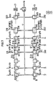
- FIG. 7 shows an arrangement in which these parallel functions are each carried out by a single functional unit will. These are given reference symbols in which the two original reference symbols are connected by a slash.
- An AU-4 management unit arriving at input 1 is processed in devices 2, 4 and 6, synchronized to the network node clock and synchronized in its TU-3x subsystem units or clockwise and in its TU-3x subsystem units or TUG-3x subsystem unit groups divided up.
- Unit 8/14 determines whether the first pointer column contains a TU-3x PTR pointer or fixed stuffing bytes FS. In the first case, only the first three bytes of the column are evaluated and taken from the signal. In the second case, however, the entire column is extracted with nine bytes.
- the VC-3x POH path frame header in unit 48 is first used for a TU-3x subsystem unit 'Dissolved. This step does not apply to a TUG-3x subsystem unit group.
- the m TU-ly-PTR pointers must then be evaluated in unit 16 with the aid of byte H4 from the VC-4-POH path frame header or the VC-3x-POH path frame header.
- Unit 10/18 is followed by synchronization to the switching network clock and superframe and insertion of the TU-3x PTR (KF) pointers or TU-ly-PTR (KF) pointers of the switching network.
- the D39 or D52 signal is formed by adding the additional switching network information KFOH in the unit 12/20.
- the multiplex signal is constructed in the opposite direction between the input 24 and the output 38 accordingly. All functional units are controlled via a bus system 57 by a microprocessor 55 which is connected to a network management system via a connection 56.
Landscapes
- Engineering & Computer Science (AREA)
- Computer Networks & Wireless Communication (AREA)
- Signal Processing (AREA)
- Time-Division Multiplex Systems (AREA)
- Use Of Switch Circuits For Exchanges And Methods Of Control Of Multiplex Exchanges (AREA)
- Data Exchanges In Wide-Area Networks (AREA)
- Compression, Expansion, Code Conversion, And Decoders (AREA)
Applications Claiming Priority (4)
| Application Number | Priority Date | Filing Date | Title |
|---|---|---|---|
| DE3928905 | 1989-08-31 | ||
| DE3928905 | 1989-08-31 | ||
| DE3930007 | 1989-09-08 | ||
| DE3930007 | 1989-09-08 |
Publications (3)
| Publication Number | Publication Date |
|---|---|
| EP0415112A2 true EP0415112A2 (fr) | 1991-03-06 |
| EP0415112A3 EP0415112A3 (en) | 1992-06-10 |
| EP0415112B1 EP0415112B1 (fr) | 1995-11-02 |
Family
ID=25884631
Family Applications (1)
| Application Number | Title | Priority Date | Filing Date |
|---|---|---|---|
| EP90114796A Expired - Lifetime EP0415112B1 (fr) | 1989-08-31 | 1990-08-01 | Procédé d'interconnexion (cross-connect) pour signaux STM-1 d'une hiérarchie multiplex synchrone et numérique |
Country Status (17)
| Country | Link |
|---|---|
| EP (1) | EP0415112B1 (fr) |
| JP (1) | JPH0695665B2 (fr) |
| CN (1) | CN1016554B (fr) |
| AT (1) | ATE129838T1 (fr) |
| AU (1) | AU613839B2 (fr) |
| BR (1) | BR9004304A (fr) |
| CA (1) | CA2024215C (fr) |
| DE (1) | DE59009834D1 (fr) |
| DK (1) | DK0415112T3 (fr) |
| ES (1) | ES2079406T3 (fr) |
| FI (1) | FI110463B (fr) |
| IE (1) | IE903147A1 (fr) |
| LU (1) | LU87713A1 (fr) |
| NO (1) | NO302266B1 (fr) |
| PT (1) | PT95143B (fr) |
| RU (1) | RU2106067C1 (fr) |
| YU (1) | YU47693B (fr) |
Cited By (3)
| Publication number | Priority date | Publication date | Assignee | Title |
|---|---|---|---|---|
| EP0505062A3 (en) * | 1991-03-22 | 1993-04-28 | Gpt Limited | Multiplex data ring transmission |
| WO1995013673A1 (fr) * | 1993-11-12 | 1995-05-18 | Nokia Telecommunications Oy | Procede de reception d'un signal dans un systeme de telecommunication numerique synchrone |
| DE19740107A1 (de) * | 1997-09-12 | 1999-03-18 | Alsthom Cge Alcatel | Verfahren zum Übertragen von Datenpaketen und zur Durchführung des Verfahrens geeignetes Netzelement |
Families Citing this family (7)
| Publication number | Priority date | Publication date | Assignee | Title |
|---|---|---|---|---|
| DE4104238A1 (de) * | 1991-02-12 | 1992-08-13 | Siemens Ag | Verfahren zum empfang und zur abgabe von rahmenkoepfen von und fuer stm-1-signale in einem rahmenkopf-server eines netzknotens |
| US5329520A (en) * | 1992-07-17 | 1994-07-12 | Alcatel Network Systems, Inc. | High-speed facility protection in a digital telecommunications system |
| US5893133A (en) * | 1995-08-16 | 1999-04-06 | International Business Machines Corporation | Keyboard for a system and method for processing Chinese language text |
| CN1076914C (zh) * | 1997-05-17 | 2001-12-26 | 华为技术有限公司 | 光同步数字传输设备的分插复用器 |
| RU2199178C1 (ru) * | 2001-06-19 | 2003-02-20 | Розенберг Ефим Наумович | Способ тактовой сетевой синхронизации генераторов |
| CN1298117C (zh) * | 2002-11-21 | 2007-01-31 | 中兴通讯股份有限公司 | 浮动指针的交叉处理的方法 |
| EP2432146B1 (fr) * | 2010-08-10 | 2014-01-15 | Huawei Technologies Co., Ltd. | Procédé, système et dispositif pour transmettre des signaux de hiérarchie numérique synchrone par micro-ondes |
Family Cites Families (5)
| Publication number | Priority date | Publication date | Assignee | Title |
|---|---|---|---|---|
| JPS61135243A (ja) * | 1984-12-06 | 1986-06-23 | Fujitsu Ltd | 多重伝送方法 |
| DE3511352A1 (de) * | 1985-03-28 | 1986-10-09 | Siemens AG, 1000 Berlin und 8000 München | Verfahren und koppeleinrichtung zum verteilen von plesiochronen breitband-digitalsignalen |
| NL8501738A (nl) * | 1985-06-17 | 1987-01-16 | Philips Nv | Hogere orde digitaal transmissiesysteem voorzien van een multiplexer en een demultiplexer. |
| CA1265227A (fr) * | 1985-07-08 | 1990-01-30 | Reginhard Pospischil | Methode pour surveiller et controler le trafic dans les reseaux de transmission numeriques |
| US4998242A (en) * | 1988-12-09 | 1991-03-05 | Transwitch Corp. | Virtual tributary cross connect switch and switch network utilizing the same |
-
1990
- 1990-04-04 LU LU87713A patent/LU87713A1/de unknown
- 1990-08-01 DK DK90114796.7T patent/DK0415112T3/da active
- 1990-08-01 DE DE59009834T patent/DE59009834D1/de not_active Expired - Fee Related
- 1990-08-01 ES ES90114796T patent/ES2079406T3/es not_active Expired - Lifetime
- 1990-08-01 EP EP90114796A patent/EP0415112B1/fr not_active Expired - Lifetime
- 1990-08-01 AT AT90114796T patent/ATE129838T1/de not_active IP Right Cessation
- 1990-08-28 YU YU163790A patent/YU47693B/sh unknown
- 1990-08-29 CA CA002024215A patent/CA2024215C/fr not_active Expired - Fee Related
- 1990-08-29 JP JP2227862A patent/JPH0695665B2/ja not_active Expired - Fee Related
- 1990-08-29 NO NO903785A patent/NO302266B1/no unknown
- 1990-08-30 AU AU61974/90A patent/AU613839B2/en not_active Ceased
- 1990-08-30 PT PT95143A patent/PT95143B/pt not_active IP Right Cessation
- 1990-08-30 IE IE314790A patent/IE903147A1/en unknown
- 1990-08-30 RU SU4830996A patent/RU2106067C1/ru not_active IP Right Cessation
- 1990-08-30 BR BR909004304A patent/BR9004304A/pt unknown
- 1990-08-30 FI FI904286A patent/FI110463B/fi not_active IP Right Cessation
- 1990-08-31 CN CN90107938.3A patent/CN1016554B/zh not_active Expired
Cited By (6)
| Publication number | Priority date | Publication date | Assignee | Title |
|---|---|---|---|---|
| EP0505062A3 (en) * | 1991-03-22 | 1993-04-28 | Gpt Limited | Multiplex data ring transmission |
| WO1995013673A1 (fr) * | 1993-11-12 | 1995-05-18 | Nokia Telecommunications Oy | Procede de reception d'un signal dans un systeme de telecommunication numerique synchrone |
| US5724342A (en) * | 1993-11-12 | 1998-03-03 | Nokia Telecommunications Oy | Method for receiving a signal in a synchronous digital telecommunications system |
| DE19740107A1 (de) * | 1997-09-12 | 1999-03-18 | Alsthom Cge Alcatel | Verfahren zum Übertragen von Datenpaketen und zur Durchführung des Verfahrens geeignetes Netzelement |
| US6236660B1 (en) | 1997-09-12 | 2001-05-22 | Alcatel | Method for transmitting data packets and network element for carrying out the method |
| US7248588B2 (en) | 1997-09-12 | 2007-07-24 | Alcatel | Method for transmitting data packets and network element for carrying out the method |
Also Published As
| Publication number | Publication date |
|---|---|
| JPH0695665B2 (ja) | 1994-11-24 |
| DK0415112T3 (da) | 1996-03-04 |
| FI904286A0 (fi) | 1990-08-30 |
| IE903147A1 (en) | 1991-03-13 |
| EP0415112A3 (en) | 1992-06-10 |
| YU163790A (sh) | 1994-04-05 |
| PT95143B (pt) | 1997-09-30 |
| FI110463B (fi) | 2003-01-31 |
| CA2024215C (fr) | 2001-06-05 |
| CN1051646A (zh) | 1991-05-22 |
| EP0415112B1 (fr) | 1995-11-02 |
| AU613839B2 (en) | 1991-08-08 |
| BR9004304A (pt) | 1991-09-03 |
| LU87713A1 (de) | 1990-07-24 |
| ES2079406T3 (es) | 1996-01-16 |
| DE59009834D1 (de) | 1995-12-07 |
| CA2024215A1 (fr) | 1991-03-01 |
| AU6197490A (en) | 1991-03-21 |
| ATE129838T1 (de) | 1995-11-15 |
| CN1016554B (zh) | 1992-05-06 |
| PT95143A (pt) | 1992-04-30 |
| RU2106067C1 (ru) | 1998-02-27 |
| JPH03102929A (ja) | 1991-04-30 |
| NO302266B1 (no) | 1998-02-09 |
| NO903785D0 (no) | 1990-08-29 |
| NO903785L (no) | 1991-03-01 |
| YU47693B (sh) | 1996-01-08 |
Similar Documents
| Publication | Publication Date | Title |
|---|---|---|
| DE69327479T2 (de) | Verfahren zum zerlegen und zusammensetzen von rahmenstrukturen mit zeigern | |
| EP0429888B1 (fr) | Méthode de transmission par un réseau multiplex hierarchisé synchrone et numérique d'un signal à large bande distribué entre des unités de transmission subordonnées | |
| DE69936697T2 (de) | Verkettung von Containern in einem SDH-Netzwerk | |
| DE60213430T2 (de) | Stm-1 bis stm-64 sdh/sonet rahmenanpasser mit datenmultiplexen aus einer serie von konfigurierbaren e/a ports | |
| DE69227736T2 (de) | Einfügen des "virtueller untergeordneter Pfad ist leer" Signals unter Verwendung des Zeitschlitzvermittlungsverfahrens | |
| DE3934248A1 (de) | Multiplexer und demultiplexer, insbesondere fuer nachrichtenuebertragungs-netze mit einer synchronen hierarchie der digitalsignale | |
| DE4104238A1 (de) | Verfahren zum empfang und zur abgabe von rahmenkoepfen von und fuer stm-1-signale in einem rahmenkopf-server eines netzknotens | |
| DE69327412T2 (de) | Verfahren und einrichtung zur elastischen pufferung in einem synchronen digitalen fernmeldesystem | |
| DE2825954C2 (de) | Digitale Zeitmultiplexanlage | |
| EP0415112B1 (fr) | Procédé d'interconnexion (cross-connect) pour signaux STM-1 d'une hiérarchie multiplex synchrone et numérique | |
| DE69219928T2 (de) | Übertragung von Multiplexdaten in einem Ring | |
| DE69322784T2 (de) | Verfahren zur durchführung einer vermittlung im zeit- oder raumbereich | |
| EP1051057A2 (fr) | Transport de conteneurs concaténées dans une réseau de transmission synchrone | |
| EP0598455B1 (fr) | Système de transmission pour la hiérarchie numérique synchrone | |
| EP0428522B1 (fr) | Procede pour connecter et deconnecter des signaux dans ou a partir de sous-domaines des signaux supplementaires de modules de transmission d'une hierarchie synchrone de signaux numeriques | |
| DE69320478T2 (de) | Verfahren und einrichtung zur überwachung der füllrate eines elastischen pufferspeichers in einem synchronen digitalen fernmeldesystem | |
| DE60203690T2 (de) | Verfahren und Vorrichtung zur Übertragung eines SDH/SONET Client-Signals als Dienstleistung | |
| DE69428434T2 (de) | Verfahren zur steuerung von bedingten verbindungen in einem synchronen digitalen fernmeldesystem | |
| DE60320266T2 (de) | Synchroner übertragungsnetzknoten | |
| EP1083693B1 (fr) | Procédé et dispositif pour transformer un signal du type SONET au signal du type SDH ( HNS) | |
| EP1191725A2 (fr) | Module de transport pour SDH/SONET | |
| DE60201052T2 (de) | Verfahren zum transparenten Transport von Rahmen mit reduziertem Overhead zwischen zwei Netzwerken durch ein Übergangsnetzwerk, das einen gemeinsamen Rahmen mit erweiterter Nutzlast überträgt | |
| EP0006986B1 (fr) | Système de transmission de données, procédé de mise en oeuvre du dit système, et circuit pour le dit système | |
| EP0993711B1 (fr) | Procede et circuit pour l'adaptation et la commutation d'un flux de donnees | |
| EP1217867A2 (fr) | Dispositif de brassage pour commutation arbitraire des signaux de communication entre des planes de multiplexage différentes |
Legal Events
| Date | Code | Title | Description |
|---|---|---|---|
| PUAI | Public reference made under article 153(3) epc to a published international application that has entered the european phase |
Free format text: ORIGINAL CODE: 0009012 |
|
| 17P | Request for examination filed |
Effective date: 19901205 |
|
| AK | Designated contracting states |
Kind code of ref document: A2 Designated state(s): AT BE CH DE DK ES FR GB GR IT LI NL SE |
|
| PUAL | Search report despatched |
Free format text: ORIGINAL CODE: 0009013 |
|
| AK | Designated contracting states |
Kind code of ref document: A3 Designated state(s): AT BE CH DE DK ES FR GB GR IT LI NL SE |
|
| 17Q | First examination report despatched |
Effective date: 19940816 |
|
| GRAA | (expected) grant |
Free format text: ORIGINAL CODE: 0009210 |
|
| AK | Designated contracting states |
Kind code of ref document: B1 Designated state(s): AT BE CH DE DK ES FR GB GR IT LI NL SE |
|
| PG25 | Lapsed in a contracting state [announced via postgrant information from national office to epo] |
Ref country code: GR Free format text: LAPSE BECAUSE OF FAILURE TO SUBMIT A TRANSLATION OF THE DESCRIPTION OR TO PAY THE FEE WITHIN THE PRESCRIBED TIME-LIMIT Effective date: 19951102 |
|
| REF | Corresponds to: |
Ref document number: 129838 Country of ref document: AT Date of ref document: 19951115 Kind code of ref document: T |
|
| REF | Corresponds to: |
Ref document number: 59009834 Country of ref document: DE Date of ref document: 19951207 |
|
| REG | Reference to a national code |
Ref country code: ES Ref legal event code: FG2A Ref document number: 2079406 Country of ref document: ES Kind code of ref document: T3 |
|
| ITF | It: translation for a ep patent filed | ||
| REG | Reference to a national code |
Ref country code: CH Ref legal event code: NV Representative=s name: SIEMENS-ALBIS AKTIENGESELLSCHAFT |
|
| GBT | Gb: translation of ep patent filed (gb section 77(6)(a)/1977) |
Effective date: 19960111 |
|
| ET | Fr: translation filed | ||
| REG | Reference to a national code |
Ref country code: DK Ref legal event code: T3 |
|
| PLBE | No opposition filed within time limit |
Free format text: ORIGINAL CODE: 0009261 |
|
| STAA | Information on the status of an ep patent application or granted ep patent |
Free format text: STATUS: NO OPPOSITION FILED WITHIN TIME LIMIT |
|
| 26N | No opposition filed | ||
| REG | Reference to a national code |
Ref country code: GB Ref legal event code: IF02 |
|
| PGFP | Annual fee paid to national office [announced via postgrant information from national office to epo] |
Ref country code: DE Payment date: 20041018 Year of fee payment: 15 |
|
| PGFP | Annual fee paid to national office [announced via postgrant information from national office to epo] |
Ref country code: CH Payment date: 20041110 Year of fee payment: 15 |
|
| PGFP | Annual fee paid to national office [announced via postgrant information from national office to epo] |
Ref country code: AT Payment date: 20050720 Year of fee payment: 16 |
|
| PGFP | Annual fee paid to national office [announced via postgrant information from national office to epo] |
Ref country code: NL Payment date: 20050805 Year of fee payment: 16 |
|
| PGFP | Annual fee paid to national office [announced via postgrant information from national office to epo] |
Ref country code: GB Payment date: 20050809 Year of fee payment: 16 |
|
| PGFP | Annual fee paid to national office [announced via postgrant information from national office to epo] |
Ref country code: SE Payment date: 20050811 Year of fee payment: 16 |
|
| PGFP | Annual fee paid to national office [announced via postgrant information from national office to epo] |
Ref country code: DK Payment date: 20050815 Year of fee payment: 16 |
|
| PGFP | Annual fee paid to national office [announced via postgrant information from national office to epo] |
Ref country code: ES Payment date: 20050817 Year of fee payment: 16 Ref country code: BE Payment date: 20050817 Year of fee payment: 16 |
|
| PGFP | Annual fee paid to national office [announced via postgrant information from national office to epo] |
Ref country code: FR Payment date: 20050819 Year of fee payment: 16 |
|
| PG25 | Lapsed in a contracting state [announced via postgrant information from national office to epo] |
Ref country code: CH Free format text: LAPSE BECAUSE OF NON-PAYMENT OF DUE FEES Effective date: 20050831 Ref country code: LI Free format text: LAPSE BECAUSE OF NON-PAYMENT OF DUE FEES Effective date: 20050831 |
|
| PG25 | Lapsed in a contracting state [announced via postgrant information from national office to epo] |
Ref country code: DE Free format text: LAPSE BECAUSE OF NON-PAYMENT OF DUE FEES Effective date: 20060301 |
|
| REG | Reference to a national code |
Ref country code: CH Ref legal event code: PL |
|
| PG25 | Lapsed in a contracting state [announced via postgrant information from national office to epo] |
Ref country code: AT Free format text: LAPSE BECAUSE OF NON-PAYMENT OF DUE FEES Effective date: 20060801 |
|
| PG25 | Lapsed in a contracting state [announced via postgrant information from national office to epo] |
Ref country code: SE Free format text: LAPSE BECAUSE OF NON-PAYMENT OF DUE FEES Effective date: 20060802 |
|
| PG25 | Lapsed in a contracting state [announced via postgrant information from national office to epo] |
Ref country code: DK Free format text: LAPSE BECAUSE OF NON-PAYMENT OF DUE FEES Effective date: 20060831 Ref country code: BE Free format text: LAPSE BECAUSE OF NON-PAYMENT OF DUE FEES Effective date: 20060831 |
|
| PGFP | Annual fee paid to national office [announced via postgrant information from national office to epo] |
Ref country code: IT Payment date: 20060831 Year of fee payment: 17 |
|
| PG25 | Lapsed in a contracting state [announced via postgrant information from national office to epo] |
Ref country code: NL Free format text: LAPSE BECAUSE OF NON-PAYMENT OF DUE FEES Effective date: 20070301 |
|
| REG | Reference to a national code |
Ref country code: DK Ref legal event code: EBP |
|
| EUG | Se: european patent has lapsed | ||
| GBPC | Gb: european patent ceased through non-payment of renewal fee |
Effective date: 20060801 |
|
| NLV4 | Nl: lapsed or anulled due to non-payment of the annual fee |
Effective date: 20070301 |
|
| REG | Reference to a national code |
Ref country code: FR Ref legal event code: ST Effective date: 20070430 |
|
| REG | Reference to a national code |
Ref country code: ES Ref legal event code: FD2A Effective date: 20060802 |
|
| PG25 | Lapsed in a contracting state [announced via postgrant information from national office to epo] |
Ref country code: GB Free format text: LAPSE BECAUSE OF NON-PAYMENT OF DUE FEES Effective date: 20060801 |
|
| BERE | Be: lapsed |
Owner name: *SIEMENS A.G. Effective date: 20060831 |
|
| PG25 | Lapsed in a contracting state [announced via postgrant information from national office to epo] |
Ref country code: ES Free format text: LAPSE BECAUSE OF NON-PAYMENT OF DUE FEES Effective date: 20060802 |
|
| PG25 | Lapsed in a contracting state [announced via postgrant information from national office to epo] |
Ref country code: FR Free format text: LAPSE BECAUSE OF NON-PAYMENT OF DUE FEES Effective date: 20060831 |
|
| PG25 | Lapsed in a contracting state [announced via postgrant information from national office to epo] |
Ref country code: IT Free format text: LAPSE BECAUSE OF NON-PAYMENT OF DUE FEES Effective date: 20070801 |