EP0415295B1 - Procédé de filage à fausse torsion et dispositif pour la mise en oeuvre de ce procédé - Google Patents
Procédé de filage à fausse torsion et dispositif pour la mise en oeuvre de ce procédé Download PDFInfo
- Publication number
- EP0415295B1 EP0415295B1 EP19900116320 EP90116320A EP0415295B1 EP 0415295 B1 EP0415295 B1 EP 0415295B1 EP 19900116320 EP19900116320 EP 19900116320 EP 90116320 A EP90116320 A EP 90116320A EP 0415295 B1 EP0415295 B1 EP 0415295B1
- Authority
- EP
- European Patent Office
- Prior art keywords
- spinning
- twisting element
- draft
- sliver
- rollers
- Prior art date
- Legal status (The legal status is an assumption and is not a legal conclusion. Google has not performed a legal analysis and makes no representation as to the accuracy of the status listed.)
- Expired - Lifetime
Links
Images


Classifications
-
- D—TEXTILES; PAPER
- D01—NATURAL OR MAN-MADE THREADS OR FIBRES; SPINNING
- D01H—SPINNING OR TWISTING
- D01H1/00—Spinning or twisting machines in which the product is wound-up continuously
- D01H1/11—Spinning by false-twisting
-
- B—PERFORMING OPERATIONS; TRANSPORTING
- B65—CONVEYING; PACKING; STORING; HANDLING THIN OR FILAMENTARY MATERIAL
- B65H—HANDLING THIN OR FILAMENTARY MATERIAL, e.g. SHEETS, WEBS, CABLES
- B65H54/00—Winding, coiling, or depositing filamentary material
- B65H54/02—Winding and traversing material on to reels, bobbins, tubes, or like package cores or formers
- B65H54/026—Doubling winders, i.e. for winding two or more parallel yarns on a bobbin, e.g. in preparation for twisting or weaving
-
- B—PERFORMING OPERATIONS; TRANSPORTING
- B65—CONVEYING; PACKING; STORING; HANDLING THIN OR FILAMENTARY MATERIAL
- B65H—HANDLING THIN OR FILAMENTARY MATERIAL, e.g. SHEETS, WEBS, CABLES
- B65H2701/00—Handled material; Storage means
- B65H2701/30—Handled filamentary material
- B65H2701/31—Textiles threads or artificial strands of filaments
Definitions
- the invention relates to a method for false wire spinning of a spinning master fed as a single sliver by means of a drafting device, at least one mechanical swirl device and a pair of take-off rollers and a device for carrying out the method.
- the cladding fibers must be separated from the core fibers, that is to say at least to a certain extent, so that the cladding fibers can be rotated around the rotated core at a gradient angle that deviates from the pitch angle of the core.
- the separation or separation of the sheath fibers from the core fibers is always at least partially from those Conditions in the swirl generation zone dependent. This statement is explained in more detail below in the description of the figures and in connection with various variants of the false wire spinning process.
- the object of the invention is to provide a method and a device with which a more uniform yarn can be produced. This object becomes clearer in connection with the following description of the prior art.
- sheath fibers are wound around the wrongly twisted core in such a way that when the false twist is subsequently removed, the sheath fibers at least partially get a real twist. All known methods to achieve this goal are based on a single principle:
- a sheath fiber is connected to the rotating thread at one end and braked at another point, so that the rotation of the thread leads to a wrapping of the sheath fiber around the wrongly rotated core. All variants of this method are suitable for use in the new spinning process.
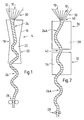
- FIG. 1 shows an air spinning process according to US-A-4 124 972.
- this document is expressly declared to be part of the present application.
- reference numeral 10 indicates the nip line of a pair of delivery rollers of a drafting system, not shown, whereby fiber material 12 is delivered to a spinning device 14.
- the spinning device 14 comprises a guide part 16, a throttle part 18 and a swirl generating part 20.
- the part 20 is provided with air nozzles, not shown, in order to generate a rotating air flow in the swirl chamber 22, so that the fiber structure 24 in the guide part 16 is rotated about its own longitudinal axis . After the twist chamber 22, the rotation of the fibers is largely canceled again according to the false twist principle in order to form an essentially untwisted yarn core.
- Part of the core twist is transferred to the sheath fibers, which loop around the incorrectly twisted fiber structure 24 in parts 16 and 20 with a pitch angle that deviates from the pitch angle of the core fibers.
- these sheath fibers continue to wrap around the core fibers and determine the strength of the finished spun yarn 26, which is drawn off by a pair of take-off rollers 28.
- the fiber material 12 supplied by the drafting system consists in the clamping line 10 of an essentially parallelized sliver without great cohesion.
- the fibers must be combined into a solidified fiber structure within the spinning triangle 30 by propagating the rotation of the wrongly rotated core. This structure must have sufficient strength to withstand the spinning tension.
- the conditions in the spinning triangle 30 are explained in more detail below in connection with FIG. 3.
- the spinning conditions in a further variant of the air spinning process will be explained with reference to FIG. 2, but elements which act essentially identically have been provided with the same reference numerals as in FIG. 1.
- FIG. 2 corresponds to the description of FIG. 5 of US reissue patent 31,705. That in the clamping line 10 of the drafting system, not shown existing fiber material 12 is combined into a fiber structure 24A by propagation of the rotation of the incorrectly rotated core. The rotation of the core is generated in a swirl device 32 with air nozzles (not shown) and a swirl chamber 34. However, the system differs considerably from the system according to FIG. 1 in that a second swirl generator 36 with air nozzles (not shown) and a swirl chamber 38 is present between the swirl generator 32 and the drafting system.
- the swirl generator 36 produces a rotation opposite to the action of the swirl generator 32, which, according to US reissue patent 31 705, prevents the full rotation of the core from propagating into the spinning triangle and loosens the fiber structure with the corresponding production of sheath fibers.
- This effect of the swirl generator 36 is to be caused by balloon formation in the swirl chamber 38, for which purpose the openings and outlets 40 and 42 of the chamber 38 have to be narrowed to form nodes of the balloon. Whether this explanation of the effect of the swirl generator 36 is exactly correct can be left open here.
- the conditions in the swirl chambers 22 and 34 are initially explained in more detail.
- the swirl chambers according to US-A-4 124 972 and US-RE-31 705 are not identical to one another and are accordingly not provided with the same reference symbols here. In one respect, however, they must work in the same way, namely in the formation of a spiral in the yarn 26 and 26a between the swirl chamber and the pair of take-off rolls 28. Without this spiral formation, no rotation of the yarn core and therefore no propagation of the core twist up to the spinning triangle 30 is produced.
- FIG. 3A shows the Guide part 16 of the spinning device, the clamping line 10, the fiber material 12 and the spinning triangle 30.
- part 16 has been omitted, but continues to show the same spinning system at different times. It can be assumed that the drafting system delivers fibers over a certain width S of the clamping line 10. Most of the fibers 12 are incorporated into the wrongly rotated core within the spinning triangle 30.
- the tail of the fiber F is either pushed into the spinning triangle 30 and integrated in the core (FIG. 3D) or only released by the clamping line 10.
- edge fiber F If the edge fiber F is not too short and therefore is not released too quickly by the clamping line 10, the tensile force exerted on the fiber F leads to a displacement of the structure 24 from the original central position in relation to the delivery width S (FIG. 3A) in one direction against the still bound end of the edge fiber F ( Figures 3C and 3D). This leads to the asymmetry of the spinning triangle 30, which can be clearly seen in FIG. 3D. This asymmetry results in conditions in the spinning triangle which are suitable for producing an edge fiber R at the left end of the delivery width S (FIG. 3D). In a method according to US-A-4 124 972, the structure 24 therefore oscillates from side to side of the delivery width S (FIG. 3E).
- This oscillation or pendulum movement P plays an essential role in the production of edge fibers in such a process. However, it is dependent on a lower voltage in the structure 24. The pulling force exerted on the yarn 26 by the pair of draw rollers 28 must not exceed a certain value without affecting the conditions in or around the spinning triangle.
- the free fiber length is stretched by friction on the walls of the channel.
- an air vortex is generated through the bores 38 in the swirl generator 36, which swings over the free end of the edge fibers RF 'in the thread running direction, and then winds around the rotating core in the opposite direction of rotation.
- there are stable conditions in the spinning triangle 30 that can remain symmetrical. These conditions are brought about by the narrowed mouth 40 and its proximity to the tip of the spinning triangle 30.
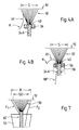
- a spinning device 50 essentially consists of a drafting device 51, a guide element 55, a mechanical swirl element 58 and a pair of draw-off rollers 59.
- the drafting device 51 consists of a pair of draw-in rollers 52, an apron drafting device 53 and a pair of delivery rollers 54.
- FIG. 5 contains the guide element 55 a nozzle 55A with a funnel-shaped inlet and a nozzle channel 56. Just before the outlet of the funnel-shaped inlet, transverse bores 57A are arranged which are connected to a vacuum source (not shown) for suction.
- Tangential bores 57B are provided behind the mouth or throttle point 56A of the nozzle channel 56.
- the mechanical swirl member 58 consists of two disks 58A, which are arranged in parallel planes with an overlapping area and can be driven in opposite directions, so that the continuous sliver undergoes rotation by friction in the hatched area and is spun into a yarn 61.
- the guide element 55 of the spinning device 50 includes a nozzle 55B with a continuous, continuous nozzle channel 56 and bores 57B opening tangentially therein, which form an obtuse angle with the thread running direction.
- the mechanical swirl member 58 here consists of two belts 58B which move in opposite directions.
- the belts 58B are endless and driven on two rollers, not shown.
- the continuous sliver receives a rotational movement and a pull.
- the main delays in the actual spinning zone are the delay ⁇ 1, that is, the ratio of the throughput speed V L of the sliver 60 on the delivery roller pair 54 of the drafting device 51 and the speed V D on the mechanical swirl member 58, and the delay ⁇ 2 means the ratio of the speed V L and the speed V A of the yarn 61 on the pair of draw-off rollers 59.
- the ratio of the two delays ⁇ 1: ⁇ 2 is now chosen so that a high spinning tension between the nip line of the delivery rollers 54 and the mechanical twist element 58 is achieved.
- This high spinning tension prevents the spinning triangle 30 of the sliver 60 from oscillating no longer or at least insignificantly along the nip line of the delivery roller pair 54 (FIG. 7).
- the formation of a locally stable spinning triangle has the advantage that it affects the Stability of the spinning conditions are clearly predictable.
- Fibers F1 and F2 which are supplied outside this length SD, serve as edge fibers, that is to say as sheath or wrapping fibers.
- the distance between the mouth of the nozzle channel 56 of the guide element 55 and the clamping line 10 is 60 to 75%, preferably 68 to 72%, of the average fiber length of the fiber sliver to be spun.
- the warp ⁇ 1 is advantageously greater than 1, the warp ⁇ 2 is set about 1, so that a spinning tension of at least 1.5 cN-tex is established.
- the size and shape of the spinning triangle 30 (FIG. 7) is determined by the spinning tension (thread tension), but the number of edge fibers can be determined independently via the total delivery width B set by the drafting system.
Landscapes
- Engineering & Computer Science (AREA)
- Textile Engineering (AREA)
- Mechanical Engineering (AREA)
- Spinning Or Twisting Of Yarns (AREA)
Claims (10)
- Procédé de filage à fausse torsion avec une alimentation de filage conçue par un ruban de fibres unique (60), réalisé à l'aide d'un train d'étirage (51), d'au moins un donneur de torsion mécanique (58), et d' une paire de rouleaux d'extraction (59),
caractérisé par le fait que,
par un réglage approprié du premier étirage (λ₁) situé entre le train d'étirage (51) et le donneur de torsion (58), et du deuxième étirage (λ₂) situé entre le train d'étirage (51) et la paire de rouleaux d'extraction (59), on obtient, entre la ligne de pinçage (10) du dernier rouleau (54) du train d'étirage et le donneur de torsion (58), une tension de filage élevée de telle manière qu'une forme en pas de vis du ruban de fibres (60) faussement tordu est évitée, au moins dans la zone comprise entre la ligne de pinçage (10) et un élément de guidage de fibres (55) disposé devant le donneur de torsion. - Procédé selon revendication 1,
caractérisé par le fait que
le premier étirage (λ₁) est plus grand que 1, et le deuxième étirage (λ₂) est réglé aux environs de 1, de façon a ce que la tension de filage soit au moins de 1,5 cN/tex. - Dispositif pour réaliser le procédé selon revendication 1 ou 2, avec un train d'étirage (51) qui détermine la vitesse de passage (VL) du ruban de fibres (60) dans la paire de rouleaux délivreurs (54), et un donneur de torsion mécanique (58), une paire de rouleaux d'extraction (59), et une buse (55A, 55B) produisant de la torsion, située entre le train d'étirage (51) et le donneur de torsion (58),
caractérisé par le fait
qu'un premier étirage (λ₁) peut être choisi à l'aide du rapport existant entre ladite vitesse de passage et la vitesse (VD) au donneur de torsion (58), et qu'un deuxième étirage (λ₂) peut être choisi à l'aide du rapport existant entre ladite vitesse de passage et la vitesse (VA) de la paire de rouleaux d'extraction (59), et que, a l'aide du premier étirage (λ₁) et du deuxième étirage (λ₂), on peut obtenir une telle tension de filage entre la ligne de pinçage (10) du dernier rouleau (54) du train d'étirage et le donneur de torsion (58) qu'une forme en pas de vis du ruban de fibres (60) faussement tordu est évitée, au moins dans la zone comprise entre la ligne de pinçage (10) et la buse (55) disposée devant le donneur de torsion. - Dispositif selon revendication 3,
caractérisé par le fait que
la buse (55A) produisant la torsion possède une entrée en forme d'entonnoir. - Dispositif selon revendication 4,
caractérisé par le fait
qu'un lieu d'étranglement (56A) en forme d'entonnoir est prévu à la fin de l'entrée, dont le diamètre est essentiellement plus petit que le diamètre du canal longitudinal (56) de la buse. - Dispositif selon revendication 3,
caractérisé par le fait que
la buse (55B) produisant la torsion possède un canal (56) continuellement cylindrique de bout en bout, dans lequel des trous tangentiels (57B) sont prévus, et réalisés avec un angle obtus par rapport à la direction de déplacement du fil. - Dispositif selon l'une des revendications 3 à 6,
caractérisé par le fait que
la distance, comprise entre l'embouchure du canal de buse (56) de la buse (55A, 55B) produisant la torsion et la ligne de pinçage (10) de la dernière paire de rouleaux (54) du train d'étirage (51), s'élève jusqu'à 75%, de préférence de 68 à 72%, de la longueur moyenne des fibres du ruban de fibres (60) à filer. - Dispositif selon l'une des revendications 3 à 7,
caractérisé par le fait que
le donneur de torsion (58) est constitué par deux disques (58A), tournant en sens inverse et se frottant l'un contre l'autre dans une zone de frottement, disques qui sont situés dans un plan disposé d'une manière essentiellement parallèle à la direction de déplacement du fil. - Dispositif selon revendication 8,
caractérisé par le fait que
les disques (58A) sont constitués par une matière en caoutchouc élastique, de préférence en polyuréthane. - Dispositif selon l'une des revendications 3 à 7,
caractérisé par le fait que
le donneur de torsion (58) est constitué par deux courroies (58B), croisées l'une par rapport a l'autre et entraînées en sens inverse, qui sont disposées en biais par rapport à la direction de déplacement du fil, et le ruban de fibres (60) se déplace en passant entre les surfaces croisées de ces courroies.
Applications Claiming Priority (2)
| Application Number | Priority Date | Filing Date | Title |
|---|---|---|---|
| CH3184/89 | 1989-09-01 | ||
| CH318489 | 1989-09-01 |
Publications (2)
| Publication Number | Publication Date |
|---|---|
| EP0415295A1 EP0415295A1 (fr) | 1991-03-06 |
| EP0415295B1 true EP0415295B1 (fr) | 1995-04-19 |
Family
ID=4250452
Family Applications (1)
| Application Number | Title | Priority Date | Filing Date |
|---|---|---|---|
| EP19900116320 Expired - Lifetime EP0415295B1 (fr) | 1989-09-01 | 1990-08-25 | Procédé de filage à fausse torsion et dispositif pour la mise en oeuvre de ce procédé |
Country Status (3)
| Country | Link |
|---|---|
| EP (1) | EP0415295B1 (fr) |
| JP (1) | JP3095230B2 (fr) |
| DE (1) | DE59008923D1 (fr) |
Families Citing this family (2)
| Publication number | Priority date | Publication date | Assignee | Title |
|---|---|---|---|---|
| JP2570663Y2 (ja) * | 1992-10-09 | 1998-05-06 | 村田機械株式会社 | 紡績装置 |
| DE102009034206A1 (de) * | 2009-07-17 | 2011-01-27 | Maschinenfabrik Rieter Ag | Bauteil für eine Luftdüsenspinnvorrichtung |
Family Cites Families (6)
| Publication number | Priority date | Publication date | Assignee | Title |
|---|---|---|---|---|
| DE2722319B2 (de) * | 1977-01-10 | 1981-01-15 | Toyo Boseki K.K., Osaka (Japan) | Vorrichtung zum pneumatischen Falschdrallspinnen |
| IN161355B (fr) * | 1983-07-01 | 1987-11-14 | Rieter Ag Maschf | |
| JPS62117830A (ja) * | 1985-11-15 | 1987-05-29 | Murata Mach Ltd | 紡績糸の製造装置 |
| DE3541219A1 (de) * | 1985-11-21 | 1987-05-27 | Schubert & Salzer Maschinen | Verfahren und vorrichtung zum verspinnen von fasern |
| US4823545A (en) * | 1987-08-31 | 1989-04-25 | Maschinenfabrik Rieter Ag | Method of and apparatus for false-twist spinning |
| JPH01162829A (ja) * | 1987-12-18 | 1989-06-27 | Mas Fab Rieter Ag | 空気ジェットノズル及び該ノズルの加撚部分で回転空気層を形成する方法 |
-
1990
- 1990-08-25 EP EP19900116320 patent/EP0415295B1/fr not_active Expired - Lifetime
- 1990-08-25 DE DE59008923T patent/DE59008923D1/de not_active Expired - Fee Related
- 1990-08-31 JP JP02228488A patent/JP3095230B2/ja not_active Expired - Fee Related
Also Published As
| Publication number | Publication date |
|---|---|
| DE59008923D1 (de) | 1995-05-24 |
| JP3095230B2 (ja) | 2000-10-03 |
| JPH0390636A (ja) | 1991-04-16 |
| EP0415295A1 (fr) | 1991-03-06 |
Similar Documents
| Publication | Publication Date | Title |
|---|---|---|
| DE2620118C3 (de) | Vorrichtung zum Spinnen von Fasergarn | |
| DE2909615C2 (de) | Vorrichtung zum Herstellen eines Garnes | |
| EP0057015B1 (fr) | Procédé et dispositif pour la fabrication d'un fil d'effet | |
| EP1223236A2 (fr) | Dispositif pour la production d'un fil d'âme | |
| EP0165398B1 (fr) | Procédé et dispositif pour réaliser un fil par filature à friction | |
| DE2049186B2 (de) | Verfahren und Vorrichtung zur Herstellung eines Garns | |
| EP0279434B1 (fr) | Procédé et dispositif pour améliorer un fil fabriqué dans le rotor d'un métier à filer à bout libre | |
| CH679679A5 (fr) | ||
| DE3207136A1 (de) | Verfahren und vorrichtung zum herstellen eines fadens | |
| CH682825A5 (de) | Vorrichtung zur Herstellung von Spinngarn. | |
| DE10251727A1 (de) | Verfahren und Vorrichtung zur Herstellung von Flyerlunte | |
| DE1303605B (fr) | ||
| DE3304827C2 (de) | Verfahren und Vorrichtung zur Herstellung von Kerngarnen | |
| DE3823725A1 (de) | Universalverfahren zum aufdrehen, entwirren und oeffnen eines textilgarns und vorrichtung zur durchfuehrung des verfahrens | |
| EP0341405B1 (fr) | Procédé et dispositif pour améliorer un fil fabriqué dans le rotor d'un métier à filer à bout libre | |
| EP0415295A1 (fr) | Procédé de filage à fausse torsion et dispositif pour la mise en oeuvre de ce procédé | |
| DE3810860A1 (de) | Verfahren und vorrichtung zum turbulenzspinnen zur herstellung von faserbuendelgarn | |
| CH659666A5 (de) | Einrichtung zum herstellen von buendelgarn. | |
| EP0606434B1 (fr) | Dispositif de filage d'un ruban de fibres | |
| AT386620B (de) | Vorrichtung zum herstellen eines garnes | |
| AT393843B (de) | Vorrichtung zum herstellen eines garnes | |
| DE3248390A1 (de) | Luftwirbelduese zum spinnen eines faserbuendelgarnes | |
| AT385526B (de) | Vorrichtung zum herstellen eines garnes | |
| AT386621B (de) | Vorrichtung zum herstellen eines garnes | |
| AT354906B (de) | Vorrichtung zum herstellen eines garnes |
Legal Events
| Date | Code | Title | Description |
|---|---|---|---|
| PUAI | Public reference made under article 153(3) epc to a published international application that has entered the european phase |
Free format text: ORIGINAL CODE: 0009012 |
|
| AK | Designated contracting states |
Kind code of ref document: A1 Designated state(s): CH DE FR LI |
|
| 17P | Request for examination filed |
Effective date: 19910115 |
|
| 17Q | First examination report despatched |
Effective date: 19920722 |
|
| GRAA | (expected) grant |
Free format text: ORIGINAL CODE: 0009210 |
|
| AK | Designated contracting states |
Kind code of ref document: B1 Designated state(s): CH DE FR LI |
|
| REF | Corresponds to: |
Ref document number: 59008923 Country of ref document: DE Date of ref document: 19950524 |
|
| PGFP | Annual fee paid to national office [announced via postgrant information from national office to epo] |
Ref country code: CH Payment date: 19950717 Year of fee payment: 6 |
|
| ET | Fr: translation filed | ||
| PLBE | No opposition filed within time limit |
Free format text: ORIGINAL CODE: 0009261 |
|
| STAA | Information on the status of an ep patent application or granted ep patent |
Free format text: STATUS: NO OPPOSITION FILED WITHIN TIME LIMIT |
|
| 26N | No opposition filed | ||
| PG25 | Lapsed in a contracting state [announced via postgrant information from national office to epo] |
Ref country code: FR Effective date: 19960430 |
|
| REG | Reference to a national code |
Ref country code: FR Ref legal event code: ST |
|
| PG25 | Lapsed in a contracting state [announced via postgrant information from national office to epo] |
Ref country code: LI Effective date: 19960831 Ref country code: CH Effective date: 19960831 |
|
| REG | Reference to a national code |
Ref country code: CH Ref legal event code: PL |
|
| PGFP | Annual fee paid to national office [announced via postgrant information from national office to epo] |
Ref country code: DE Payment date: 20030724 Year of fee payment: 14 |
|
| PG25 | Lapsed in a contracting state [announced via postgrant information from national office to epo] |
Ref country code: DE Free format text: LAPSE BECAUSE OF NON-PAYMENT OF DUE FEES Effective date: 20050301 |