EP0416511B1 - Verfahren zur Kraftstoffeinspritzung für eine Brennkraftmaschine - Google Patents
Verfahren zur Kraftstoffeinspritzung für eine Brennkraftmaschine Download PDFInfo
- Publication number
- EP0416511B1 EP0416511B1 EP90116899A EP90116899A EP0416511B1 EP 0416511 B1 EP0416511 B1 EP 0416511B1 EP 90116899 A EP90116899 A EP 90116899A EP 90116899 A EP90116899 A EP 90116899A EP 0416511 B1 EP0416511 B1 EP 0416511B1
- Authority
- EP
- European Patent Office
- Prior art keywords
- fuel
- cylinder
- cylinders
- injection
- fuel injection
- Prior art date
- Legal status (The legal status is an assumption and is not a legal conclusion. Google has not performed a legal analysis and makes no representation as to the accuracy of the status listed.)
- Expired - Lifetime
Links
- 239000000446 fuel Substances 0.000 title claims description 198
- 238000002347 injection Methods 0.000 title claims description 57
- 239000007924 injection Substances 0.000 title claims description 57
- 238000000034 method Methods 0.000 title claims description 25
- 238000004364 calculation method Methods 0.000 claims description 9
- 230000004044 response Effects 0.000 description 19
- XLYOFNOQVPJJNP-UHFFFAOYSA-N water Substances O XLYOFNOQVPJJNP-UHFFFAOYSA-N 0.000 description 10
- 238000007796 conventional method Methods 0.000 description 6
- 230000008859 change Effects 0.000 description 4
- 230000005540 biological transmission Effects 0.000 description 3
- 238000010276 construction Methods 0.000 description 3
- 238000010586 diagram Methods 0.000 description 3
- 238000012937 correction Methods 0.000 description 2
- 230000001419 dependent effect Effects 0.000 description 2
- 230000008569 process Effects 0.000 description 2
- 230000009467 reduction Effects 0.000 description 2
- 230000001052 transient effect Effects 0.000 description 2
- QVGXLLKOCUKJST-UHFFFAOYSA-N atomic oxygen Chemical compound [O] QVGXLLKOCUKJST-UHFFFAOYSA-N 0.000 description 1
- 238000004140 cleaning Methods 0.000 description 1
- 230000006835 compression Effects 0.000 description 1
- 238000007906 compression Methods 0.000 description 1
- 238000013461 design Methods 0.000 description 1
- 238000011161 development Methods 0.000 description 1
- 230000000694 effects Effects 0.000 description 1
- 238000002474 experimental method Methods 0.000 description 1
- 239000007789 gas Substances 0.000 description 1
- 230000006872 improvement Effects 0.000 description 1
- 238000013178 mathematical model Methods 0.000 description 1
- 239000001301 oxygen Substances 0.000 description 1
- 229910052760 oxygen Inorganic materials 0.000 description 1
- 238000004088 simulation Methods 0.000 description 1
- 238000012546 transfer Methods 0.000 description 1
Images
Classifications
-
- F—MECHANICAL ENGINEERING; LIGHTING; HEATING; WEAPONS; BLASTING
- F02—COMBUSTION ENGINES; HOT-GAS OR COMBUSTION-PRODUCT ENGINE PLANTS
- F02D—CONTROLLING COMBUSTION ENGINES
- F02D41/00—Electrical control of supply of combustible mixture or its constituents
- F02D41/008—Controlling each cylinder individually
-
- F—MECHANICAL ENGINEERING; LIGHTING; HEATING; WEAPONS; BLASTING
- F02—COMBUSTION ENGINES; HOT-GAS OR COMBUSTION-PRODUCT ENGINE PLANTS
- F02D—CONTROLLING COMBUSTION ENGINES
- F02D41/00—Electrical control of supply of combustible mixture or its constituents
- F02D41/30—Controlling fuel injection
-
- F—MECHANICAL ENGINEERING; LIGHTING; HEATING; WEAPONS; BLASTING
- F02—COMBUSTION ENGINES; HOT-GAS OR COMBUSTION-PRODUCT ENGINE PLANTS
- F02D—CONTROLLING COMBUSTION ENGINES
- F02D41/00—Electrical control of supply of combustible mixture or its constituents
- F02D41/02—Circuit arrangements for generating control signals
- F02D41/04—Introducing corrections for particular operating conditions
- F02D41/047—Taking into account fuel evaporation or wall wetting
Definitions
- the present invention relates to a controlling of a car engine and, more particularly, relates to a method for controlling fuel injection in an engine, in which the delay in the flow of fuel into a cylinder is compensated to keep the quantity of fuel in the cylinder in a requested value with high accuracy.
- the conventional technique is constructed on the assumption that some percent of injected fuel always reaches the cylinder.
- the conventional technique has a control algorism in which such flow of fuel is compensated. Therefore, a problem arises in that the delay of fuel caused by stagnancy of all the injected fuel in the intake manifold cannot be compensated.
- actual fuel injection time must be determined under the consideration of both the phenomenon of adhesion of injected fuel and the phenomenon of sucking off the fuel film into the cylinder.
- actual fuel injection time is determined by subtracting the quantity of sucked-off fuel from the quantity of fuel injection which is determined to keep the quantity of fuel in the cylinder in a requested value under the consideration of only the phenomenon of adhesion of fuel.
- fuel control must be carried out based on estimation of the quantity of fuel film for each cylinder in order to compensate the transient delay of fuel with high accuracy because the respective cylinders are different from each other in the quantity of fuel film and in the state of injectors.
- the quantity of fuel film only in one cylinder is estimated for all cylinders, and there arises a problem in that the transient delay of fuel cannot be compensated with high accuracy.
- a method for controlling a fuel injection amount comprising the features of the preamble of claim 1 is disclosed in EP-A-0 115 868.
- This document discloses the use of a fuel transport model for calculating the fuel injection amount for the engine cylinders, wherein a single dynamic fuel transport model is provided for representing one fuel transfer characteristic used for all cylinders in common.
- EP-A-0 260 519 discloses an open-loop fuel injection method which individually controls the fuel injection amounts of the individual cylinders of a multi-cylinder engine by using a look-up table in which experimentally determined values of a correction factor are stored as a function of the engine rpm and a certain throttle valve opening degree.
- An object of the present invention is therefore to provide a method for controlling fuel injection in an engine, in which the quantity of fuel in each of all the cylinder can be kept in a requested value independently of other cylinders to thereby solve the aforementioned problems.
- the flow of fuel is formulated as a lumped constant type numeric model for each cylinder on the assumption that all injected fuel stagnates in an intake manifold and then some percent of the stagnant fuel enters into the cylinder in an air-intake stroke after fuel injection.
- the sucking-off rate expressing the rate of sucking off the stagnant fuel into the cylinder as a parameter in the model is obtained experimentally for each cylinder.
- fuel control for each cylinder is carried out according to the numeric model obtained as described above so that the quantity of fuel in the cylinder is established to be a requested value.
- a numeric model suitable to the real phenomenon is constructed to perform fuel control for each of all the cylinders separately from the other ones by using the model as a fuel transport model. Accordingly, the quantity of fuel in each of all the cylinders can be kept in a requested value separately from the other ones.
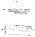
- Fig. 1 is a view showing the change of stagnant fuel in an intake manifold in the case where a certain cylinder is observed in the present invention. The effect of the invention on the flow of fuel and the change of stagnant fuel will be now described with reference to Fig. 1.
- M f (i) stagnant fuel (g) in an exhaustion stroke before fuel injection, in the fuel cycle of an engine.
- G f (i) injection fuel (g).
- M′ f (i) M f (i) + G f (i)
- stagnant fuel G fe (i) in the intake manifold is represented by the following equation.
- G fe (i) ⁇ M′ f (i)
- the stagnant fuel does not change before the next fuel injection period.
- the flow of fuel after the next fuel injection is developed in the same manner as described above.
- a lumped-constant numerical model given by the equations (1), (2) and (3) is used as a fuel transport model.
- the sucking-off rate ⁇ as a parameter changes according to the operation condition of the engine.
- the characteristic of the sucking-off rate a for each cylinder is formulated as follows.
- the air-intake quantity, the engine revolution speed, the water temperature and the intake manifold inner pressure are considered as engine state variables affecting the sucking-off rate ⁇ . Therefore, the sucking-off rate ⁇ is calculated so that the measured value thereof obtained from the response of the air-fuel ratio in each cylinder when fuel supply quantity is changed in a predetermined condition with these variables considered to be constant can coincide with the simulation value thereof estimated by using the equations (1), (2) and (3). Thus, a model suitable to the actual phenomenon is constructed.
- the aforementioned calculation of ⁇ is applied to various engine operation states so that the characteristic of ⁇ is formulated as a function of operation state variables (the suction air quantity, the engine revolution speed, the water temperature and the intake manifold inner pressure).
- the response of fuel G fe (i) sucked off into the cylinder when G f (i) is changed in a predetermined condition can be obtained by repeated calculation of the equations (4) and (5).
- the response of the air-fuel ratio can be obtained by dividing the measured value of cylinder suction air quantity Q a by the calculated value thereof.
- ⁇ is estimated.
- the response delay of the sensor is formulated in advance on the supposition of suitable transmission characteristic.
- the calculation of ⁇ is carried out based on comparison between the response of the air-fuel ratio corrected by applying the delay process to the calulated response of the air-fuel ratio and the measured response thereof.
- the response characteristic is represented by the following discrete equation: In the equation (6),
- the response of the air-fuel ratio A/F out in due consideration of the response delay of the sensor is obtained based on the equation (6) using the air-fuel ratio calculated based on the equations (4) and (5) as A/F in (i).
- the characteristic of ⁇ may be formulated by estimating ⁇ as follows.
- the fuel-air ratio F/A(i) in the i-th cycle is obtained as the reciprocal of the value A/F(i) measured with an air-fuel ratio sensor provided in an exhaust pipe.
- the response characteristic of the sensor is formulated into a suitable transmission function of the fuel-air ratio.
- the transmission characteristic is represented by the following discrete equation. In the equation (12),
- the characteristic of ⁇ is stored as fixed data in an ROM in the form of a map of the suction air quantity, the revolution speed, and the like.
- Variables dependent on ⁇ that is, the suction air quantity Q a , the revolution speed N, the water temperature T w and the intake manifold inner presure P H , are rearranged as x1, x2, x3 and x4 in the order of contribution to the sucking-out rate ⁇ .
- ⁇ is calculated from the map of these variables according to the following equations.
- ⁇ f1(x1,x2,x3) ⁇ f2(x4)
- ⁇ f3(x1,x2) ⁇ f4(x3) ⁇ f5(x4)
- f1 is a value obtained by searching a three-dimensional map of respective variables
- f3 is a value obtained by searching a two-dimensional map of respective variables
- f2, f4 and f5 are values obtained by searching one-dimensional maps of respective variables.
- f1(x1,x2,x3) m1 ⁇ 1(x1,x2,x3)
- f2(x4) m2 ⁇ 2(x4)
- map data f1 and f2 In order to determine map data f1 and f2 from the equations (17) and (18), the values of m1 and m2 must be determined.
- the values of m1 and m2 are selected so that the value of ⁇ calculated by using the equations (14), (17) and (18) for certain values of x1, x2, x3 and x4 coincides with the true value of ⁇ for these variables.
- the values of m1 and m2 cannot be determined monolithically. Therefore, a certain set of values satisfying the aforementioned condition can be used.
- Map data in the equation (15) can be calculated in the same manner as described above.
- sucking-off rate ⁇ calculated by using the equations (14) and (18) for the suction air quantity, the revolution speed, the water temperature and the intake manifold inner pressure may be more or less different from the true value of ⁇ calculated by using the equation (11), a reduction of map data can be attained by using maps having a small number of dimentions.
- G fe (i) k ⁇ Q a (i) N A/F
- A/F represents target air-fuel ratio
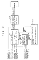
- Fig. 2 is a schematic block diagram of the whole configuration of the fuel control system according to the present invention in a certain cylinder.
- fuel supply G f (i) in the i-th cycle is calculated according to the equation (21) from the measured value of revolution speed N, the calculated value of sucking-off rate ⁇ and the calculated value of stagnant fuel M f (i) sucked in the intake manifold.
- the sucking-off rate ⁇ is calculated from the measured values of the air flow quantity, the revolution speed, the inner pressure and the water temperature according to the function obtained by the aforementioned method.
- stagnant fuel M f (i) used for determination of fuel supply is updated based on the equation (5).
- the fuel injection time (pulse width) T1 is calculated from fuel supply based on the following equation to thereby perform fuel control in the engine.
- T i k′ ⁇ G f (i) ⁇ +T s
- k′ represents a constant
- ⁇ represents a feedback correction coefficient
- T s represents an ineffective injection period.
- the control system as shown in Fig. 2 is provided for each cylinder to perform independent fuel control in each cylinder.
- the total construction of respective control systems is as shown in Fig. 6.
- the control systems as shown in Fig. 2 are provided as the blocks 61 to 64 in Fig. 6. It is a matter of course that variables G f , M f and ⁇ used in each of the control systems are established independently in the respective cylinders.
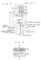
- Fig. 3 is a view showing the whole configuration of a D-jetronic system for indirectly detecting an air flow quantity based on the measured values of the intake manifold inner pressure and the revolution speed according to the present invention.
- the control unit 31 has a CPU 301, and ROM 302, an RAM 303, a timer 304, an I/O LSI 305, and a bus 306 for electrical connection thereof.
- the timer 304 generates interrupt requests for the CPU 301 at a predetermined period.
- the CPU 301 executes the control program stored in the ROM 302 in response to the interrupt requests.
- Signals from a pressure sensor 32, a throttle angle sensor 33, a water temperature sensor 34, a crank angle sensor 35, a suction air temperature sensor 36 and an oxygen sensor 37 are inputted into the I/O LSI 305.
- An output signal from the I/O LSI 305 is fed to an injector 38.
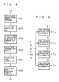
- Fig. 4 is a flow chart of the control program for calculating the fuel injection time
- Fig. 5 is a flow chart of the control program for calculating stagnant fuel in the intake manifold.
- step 401 signals from the pressure sensor, water temperature sensor, crank angle sensor and suction air temperature sensor are taken in when interrupt requests generated at intervals of 10 msec are given. Revolution count is calculated from the signal of the crank angle sensor.
- the suction air flow quantity Q a in the engine is calculated based on a predetermined equation from the values of the intake manifold inner pressure, the revolution speed and the suction air temperature which have been taken in.
- step 403 the next cylinder to be subjected to fuel injection is judged.
- the sucking-off rate ⁇ corresponding to the next cylinder to be subjected to fuel injection is calculated according to a fixed equation from the values of the intake manifold inner pressure, the revolution speed and the water temperature fetched in the step 401 and the value of the air flow quantity calculated in the step 402 and is stored in a predetermined address of the RAM.
- the fuel supply G f for the next cylinder to be subjected to fuel injection is calculated according to the equation (21) from the revolution speed N fetched in the step 401, the air flow quantity Q a calculated in the step 402, the sucking-off rate ⁇ calculated in the step 404, the stagnant fuel M f (corresponding to the next cylinder to be subjected to fuel injection) calculated by another program and stored in the RAM 303, and the target air-fuel ratio A/F.
- the fuel injection time T i corresponding to the next cylinder to be subjected to fuel injection is calculated according to the equation (22) from the fuel supply calculated in the step 405.
- the series of procedures is terminated to wait for the next interrupt request.
- the load imposed on the micro-computer can be reduced by calculating the fuel supply corresponding to the next cylinder to be subjected to fuel injection without calculating the fuel supply for all the cylinders.
- Fuel injection is carried out by feeding to the injector a pulse signal corresponding to the fuel injection time calculated in the step 406 in response to the interrupt request expressing that the crank angle has come to a predetermined position.
- the control program for estimating stagnant fuel and updating it as shown in Fig. 5 is executed after fuel injection.
- the cylinder subjected to fuel injection is judged in the step 501.
- stagnant fuel M f (i+1) used for calculation of fuel supply G f (i+1) for the cylinder in the (i+1)-th cycle is calculated according to the equation (5) from the stagnant fuel M f (i) before the fuel injection in the i-th cycle with respect to the cylinder subjected to fuel injection, the fuel supply G f (i) for the cylinder and the sucking-off rate ⁇ used for the calculation of G f (i) and the result is stored in the RAM 303 in Fig.3.
- the series of procedures is terminated.
- stagnant fuel corresponding to the cylinder subjected to fuel injection is updated after the fuel injection.
- the embodiment has shown the case where the invention is applied to a D-jetronic system, it is to be understood that the invention can be applied to an L-jetronic system in which suction air quantity is detected directly.
- the inner pressure in the intake manifold is not detected but this variable can be replaced by the basic injection pulse width.
- a fuel transport model suitable to the real phenomenon is constructed to thereby perform fuel control separately for each cylinder. Accordingly, values for requesting fuel for the respective cylinders can be held in all the cylinders. Accordingly, high-accurate air-fuel ratio control can be made to thereby attain an improvement in exhaust gas cleaning property, operating property and efficiency in fuel cost.
- the system according to the present invention can be constructed by formulating one parameter, so that the number of development processes can be reduced.
Landscapes
- Engineering & Computer Science (AREA)
- Chemical & Material Sciences (AREA)
- Combustion & Propulsion (AREA)
- Mechanical Engineering (AREA)
- General Engineering & Computer Science (AREA)
- Electrical Control Of Air Or Fuel Supplied To Internal-Combustion Engine (AREA)
Claims (7)
- Verfahren zur Regelung der Brennstoff-Einspritzmenge eines Mehrzylindermotors mit einer Einspritzdüse (38) in jedem der zu den einzelnen Zylindern führenden Rohrtrakte, mit folgenden Schritten:
Bereitstellen eines Brennstoff-Transportmodells für die Zylinder des Motors, welches umfaßt
Abschätzen eines Brennstoff-Transport zustandes der Saugrohre der Zylinder auf der Grundlage einer Brennstoff-Einspritzmenge (Gf(i-1)) in einem vorhergehenden Einspritztakt und einer Menge stagnierenden Brennstoffs (MF(i)), die zeitweilig in dem jeweiligen Saugrohr verbleibt,
Berechnen der Brennstoff-Einspritzmenge (Gf(i)) der Zylinder für den gegenwärtigen Einspritztakt gemäß dem geschätzten Brennstoff-Transportzustand,
dadurch gekennzeichnet, daß
das Transportmodell, das für jeden einzelnen Zylinder des Motors vorgesehen ist, verschiedene Modellparameterwerte für die verschiedenen Zylinder unter den gleichen Motor-Betriebszuständen aufweist, wobei die Brennstoff-Transportmodelle Brennstoff-Transportzustände der jeweiligen, mit jedem Zylinder verbundenen Saugrohre individuell definieren, und
die Brennstoff-Transportzustände bzw. die Brennstoff-Einspritzmengen (Gf(i)) unabhängig für jeden einzelnen Zylinder abgeschätzt bzw. berechnet werden. - Verfahren nach Anspruch 1, wobei jedes der Brennstoff-Transportzustände individuell durch Verwendung der Brennstoff-Einspritzmenge des entsprechenden einzelnen Zylinders unabhängig von den Brennstoffmengen in den anderen Zylindern abgeschätzt wird.
- Verfahren nach Anspruch 1, wobei die verschiedenen Brennstoff-Transportmodelle die gleiche Modellstruktur aufweisen.
- Verfahren nach Anspruch 1 oder 2, wobei im Berechnungsschritt die Brennstoff-Einspritzmengen (Gf(i)) periodisch zu einem vorgegebenen Zeitpunkt berechnet werden.
- Verfahren nach Anspruch 4, ferner umfassend einen Schritt der Bestimmung eines Zylinders, in den im nächsten Einspritztakt Brennstoff einzuspritzen ist, wobei die Brennstoff-Einspritzmenge nur für diesen Zylinder berechnet wird.
- Verfahren nach Anspruch 1, wobei die jeweiligen Brennstoff-Transportmodelle den Brennstofftransport durch die jeweiligen Saugrohre simulieren, wobei die Gesamtmenge (Gf) des eingespritzten Brennstoffs vor dem Ansaugtakt auf eine innere Wandoberfläche des Saugrohres auftrifft, zurückgebliebener Brennstoff in den jeweiligen Saugrohren nach dem Ansaugtakt zu der Gesamtmenge (Gf) des im nächsten Einspritztakt eingespritzten Brennstoffs addiert wird, um die stagnierende Brennstoffmenge (Mf) zu bilden, und anschließend ein Teil dieser stagnierenden Brennstoffmenge im nächsten Ansaugtakt nach dem Einspritztakt in die jeweiligen Zylinder transportiert wird.
- Verfahren nach Anspruch 1, wobei die Berechnung der Brennstoff-Einspritzmenge (Gf(i)) unter Berücksichtigung der Unterschiede der Brennstoff-Transportcharakteristiken unter den Zylindern durchgeführt wird.
Applications Claiming Priority (2)
| Application Number | Priority Date | Filing Date | Title |
|---|---|---|---|
| JP1227367A JPH0392557A (ja) | 1989-09-04 | 1989-09-04 | エンジンの燃料噴射制御方法 |
| JP227367/89 | 1989-09-04 |
Publications (2)
| Publication Number | Publication Date |
|---|---|
| EP0416511A1 EP0416511A1 (de) | 1991-03-13 |
| EP0416511B1 true EP0416511B1 (de) | 1994-12-21 |
Family
ID=16859693
Family Applications (1)
| Application Number | Title | Priority Date | Filing Date |
|---|---|---|---|
| EP90116899A Expired - Lifetime EP0416511B1 (de) | 1989-09-04 | 1990-09-03 | Verfahren zur Kraftstoffeinspritzung für eine Brennkraftmaschine |
Country Status (5)
| Country | Link |
|---|---|
| US (1) | US5134981A (de) |
| EP (1) | EP0416511B1 (de) |
| JP (1) | JPH0392557A (de) |
| KR (1) | KR0158880B1 (de) |
| DE (1) | DE69015283T2 (de) |
Families Citing this family (16)
| Publication number | Priority date | Publication date | Assignee | Title |
|---|---|---|---|---|
| DE4115211C2 (de) * | 1991-05-10 | 2003-04-30 | Bosch Gmbh Robert | Verfahren zum Steuern der Kraftstoffzumessung bei einer Brennkraftmaschine |
| US5261370A (en) * | 1992-01-09 | 1993-11-16 | Honda Giken Kogyo Kabushiki Kaisha | Control system for internal combustion engines |
| JPH05312072A (ja) * | 1992-05-07 | 1993-11-22 | Honda Motor Co Ltd | 内燃エンジンの空燃比制御装置 |
| EP0594114B1 (de) * | 1992-10-19 | 1999-12-15 | Honda Giken Kogyo Kabushiki Kaisha | Regelungssystem für die Brennstoffdosierung eines Innenverbrennungsmotors |
| US5421305A (en) * | 1993-01-28 | 1995-06-06 | Unisia Jecs Corporation | Method and apparatus for control of a fuel quantity increase correction amount for an internal combustion engine, and method and apparatus for detection of the engine surge-torque |
| JPH06323181A (ja) * | 1993-05-14 | 1994-11-22 | Hitachi Ltd | 内燃機関の燃料制御方法及びその装置 |
| US5345914A (en) * | 1993-08-16 | 1994-09-13 | General Motors Corporation | Electronic fuel injection control |
| JP3330234B2 (ja) * | 1994-07-29 | 2002-09-30 | 本田技研工業株式会社 | 内燃機関の燃料噴射制御装置 |
| JP3354304B2 (ja) * | 1994-07-29 | 2002-12-09 | 本田技研工業株式会社 | 内燃機関の燃料噴射制御装置 |
| US5758308A (en) * | 1994-12-30 | 1998-05-26 | Honda Giken Kogyo Kabushiki Kaisha | Fuel metering control system for internal combustion engine |
| US5657736A (en) * | 1994-12-30 | 1997-08-19 | Honda Giken Kogyo Kabushiki Kaisha | Fuel metering control system for internal combustion engine |
| KR19990075068A (ko) * | 1998-03-17 | 1999-10-05 | 윤종용 | 절연막 식각방법 및 이를 이용한 반도체장치 제조방법 |
| US6067965A (en) * | 1998-08-31 | 2000-05-30 | Ford Global Technologies, Inc. | Method and system for determining a quantity of fuel to be injected into an internal combustion engine |
| US6003496A (en) * | 1998-09-25 | 1999-12-21 | General Motors Corporation | Transient fuel compensation |
| DE102004009679B4 (de) * | 2004-02-27 | 2010-01-07 | Continental Automotive Gmbh | Verfahren und Vorrichtung zum Steuern einer Brennkraftmaschine |
| US20180156099A1 (en) * | 2016-12-06 | 2018-06-07 | GM Global Technology Operations LLC | Method of measuring an exhaust gas temperature |
Family Cites Families (12)
| Publication number | Priority date | Publication date | Assignee | Title |
|---|---|---|---|---|
| JPS6024299B2 (ja) * | 1978-07-21 | 1985-06-12 | 株式会社日立製作所 | 最適燃料供給制御装置 |
| US4357923A (en) * | 1979-09-27 | 1982-11-09 | Ford Motor Company | Fuel metering system for an internal combustion engine |
| JPS588238A (ja) * | 1981-07-06 | 1983-01-18 | Toyota Motor Corp | 燃料噴射式エンジンの燃料噴射量制御方法 |
| US4562814A (en) * | 1983-02-04 | 1986-01-07 | Nissan Motor Company, Limited | System and method for controlling fuel supply to an internal combustion engine |
| JPH0650074B2 (ja) * | 1983-08-08 | 1994-06-29 | 株式会社日立製作所 | エンジンの燃料制御方法 |
| US4667640A (en) * | 1984-02-01 | 1987-05-26 | Hitachi, Ltd. | Method for controlling fuel injection for engine |
| JP2550014B2 (ja) * | 1984-11-26 | 1996-10-30 | 株式会社日立製作所 | エンジンの燃料噴射制御方法 |
| US4939658A (en) * | 1984-09-03 | 1990-07-03 | Hitachi, Ltd. | Control method for a fuel injection engine |
| JPS6361737A (ja) * | 1986-09-01 | 1988-03-17 | Hitachi Ltd | 燃料制御装置 |
| JPS63314339A (ja) * | 1987-06-17 | 1988-12-22 | Hitachi Ltd | 空燃比制御装置 |
| JPH01182552A (ja) * | 1988-01-18 | 1989-07-20 | Hitachi Ltd | 空燃比適応制御装置 |
| JP2512787B2 (ja) * | 1988-07-29 | 1996-07-03 | 株式会社日立製作所 | 内燃機関のスロットル開度制御装置 |
-
1989
- 1989-09-04 JP JP1227367A patent/JPH0392557A/ja active Pending
-
1990
- 1990-08-23 KR KR1019900013012A patent/KR0158880B1/ko not_active Expired - Fee Related
- 1990-08-31 US US07/575,688 patent/US5134981A/en not_active Expired - Fee Related
- 1990-09-03 EP EP90116899A patent/EP0416511B1/de not_active Expired - Lifetime
- 1990-09-03 DE DE69015283T patent/DE69015283T2/de not_active Expired - Fee Related
Also Published As
| Publication number | Publication date |
|---|---|
| DE69015283D1 (de) | 1995-02-02 |
| KR910006605A (ko) | 1991-04-29 |
| KR0158880B1 (ko) | 1998-12-15 |
| EP0416511A1 (de) | 1991-03-13 |
| DE69015283T2 (de) | 1995-05-18 |
| US5134981A (en) | 1992-08-04 |
| JPH0392557A (ja) | 1991-04-17 |
Similar Documents
| Publication | Publication Date | Title |
|---|---|---|
| EP0416511B1 (de) | Verfahren zur Kraftstoffeinspritzung für eine Brennkraftmaschine | |
| EP0312835B1 (de) | Steuereinrichtung | |
| US5205260A (en) | Method for detecting cylinder air amount introduced into cylinder of internal combustion engine with exhaust gas recirculation system and for controlling fuel injection | |
| US5282449A (en) | Method and system for engine control | |
| KR940006050B1 (ko) | 엔진의 연료분사제어방법 및 장치 | |
| US4667640A (en) | Method for controlling fuel injection for engine | |
| EP0845586B1 (de) | Verfahren zur Bestimmung von pneumatischen Zuständen in einem Brennkraftmaschinensystem | |
| EP0582085A2 (de) | Brennstoffdosierungsteuersystem und Verfahren zum Schätzen des Zylinderluftstroms in Verbrennungsmotoren | |
| KR960000439B1 (ko) | Ic 엔진 연료 분사용 자동 제어 시스템 | |
| EP0594114A2 (de) | Regelungssystem für die Brennstoffdosierung eines Innenverbrennungsmotors | |
| EP0461480B1 (de) | Methode und Vorrichtung zur Kraftstoffeinspritzungssteuerung für eine Brennkraftmaschine | |
| EP0184626B1 (de) | Steuerverfahren für einen Motor mit Kraftstoffeinspritzung | |
| JP2512787B2 (ja) | 内燃機関のスロットル開度制御装置 | |
| EP0518289B1 (de) | Vorrichtung zur Regelung der Drehzahl einer Brennkraftmaschine | |
| US4792905A (en) | Method of fuel injection control in engine | |
| US4499881A (en) | Method and apparatus for controlling internal combustion engines | |
| EP0287932A2 (de) | Regelkreis mit nicht-linearer Rückkopplung für einen Motor mit innerer Verbrennung | |
| US4469074A (en) | Electronic control for internal combustion engine | |
| US5611315A (en) | Fuel supply amount control apparatus for internal combustion engine | |
| US5569847A (en) | Air-fuel ratio estimator for internal combustion engine | |
| US4995366A (en) | Method for controlling air-fuel ratio for use in internal combustion engine and apparatus for controlling the same | |
| JPS6214704B2 (de) | ||
| US6985806B2 (en) | Method for determining an estimated value of a mass flow in the intake channel of an internal combustion engine | |
| US6718942B2 (en) | Method for estimation of the quantity of fresh air present in the intake and exhaust manifolds of an internal combustion engine with a recirculation circuit | |
| US4476831A (en) | Method and apparatus for controlling the fuel supply of an internal combustion engine |
Legal Events
| Date | Code | Title | Description |
|---|---|---|---|
| PUAI | Public reference made under article 153(3) epc to a published international application that has entered the european phase |
Free format text: ORIGINAL CODE: 0009012 |
|
| AK | Designated contracting states |
Kind code of ref document: A1 Designated state(s): DE FR GB |
|
| 17P | Request for examination filed |
Effective date: 19910912 |
|
| 17Q | First examination report despatched |
Effective date: 19920206 |
|
| GRAA | (expected) grant |
Free format text: ORIGINAL CODE: 0009210 |
|
| AK | Designated contracting states |
Kind code of ref document: B1 Designated state(s): DE FR GB |
|
| REF | Corresponds to: |
Ref document number: 69015283 Country of ref document: DE Date of ref document: 19950202 |
|
| ET | Fr: translation filed | ||
| PLBE | No opposition filed within time limit |
Free format text: ORIGINAL CODE: 0009261 |
|
| STAA | Information on the status of an ep patent application or granted ep patent |
Free format text: STATUS: NO OPPOSITION FILED WITHIN TIME LIMIT |
|
| 26N | No opposition filed | ||
| REG | Reference to a national code |
Ref country code: GB Ref legal event code: IF02 |
|
| PGFP | Annual fee paid to national office [announced via postgrant information from national office to epo] |
Ref country code: FR Payment date: 20020716 Year of fee payment: 13 |
|
| PGFP | Annual fee paid to national office [announced via postgrant information from national office to epo] |
Ref country code: GB Payment date: 20020823 Year of fee payment: 13 |
|
| PGFP | Annual fee paid to national office [announced via postgrant information from national office to epo] |
Ref country code: DE Payment date: 20021125 Year of fee payment: 13 |
|
| PG25 | Lapsed in a contracting state [announced via postgrant information from national office to epo] |
Ref country code: GB Free format text: LAPSE BECAUSE OF NON-PAYMENT OF DUE FEES Effective date: 20030903 |
|
| PG25 | Lapsed in a contracting state [announced via postgrant information from national office to epo] |
Ref country code: DE Free format text: LAPSE BECAUSE OF NON-PAYMENT OF DUE FEES Effective date: 20040401 |
|
| GBPC | Gb: european patent ceased through non-payment of renewal fee | ||
| PG25 | Lapsed in a contracting state [announced via postgrant information from national office to epo] |
Ref country code: FR Free format text: LAPSE BECAUSE OF NON-PAYMENT OF DUE FEES Effective date: 20040528 |
|
| REG | Reference to a national code |
Ref country code: FR Ref legal event code: ST |