EP0416540B1 - Tête d'impression pour imprimante à jet d'encre - Google Patents
Tête d'impression pour imprimante à jet d'encre Download PDFInfo
- Publication number
- EP0416540B1 EP0416540B1 EP90116978A EP90116978A EP0416540B1 EP 0416540 B1 EP0416540 B1 EP 0416540B1 EP 90116978 A EP90116978 A EP 90116978A EP 90116978 A EP90116978 A EP 90116978A EP 0416540 B1 EP0416540 B1 EP 0416540B1
- Authority
- EP
- European Patent Office
- Prior art keywords
- ink
- nozzle
- comb
- recording head
- jet printer
- Prior art date
- Legal status (The legal status is an assumption and is not a legal conclusion. Google has not performed a legal analysis and makes no representation as to the accuracy of the status listed.)
- Expired - Lifetime
Links
- 239000000463 material Substances 0.000 claims description 10
- 238000006243 chemical reaction Methods 0.000 description 13
- 230000005684 electric field Effects 0.000 description 6
- 239000000758 substrate Substances 0.000 description 6
- 238000010276 construction Methods 0.000 description 2
- 230000001419 dependent effect Effects 0.000 description 1
- 239000000428 dust Substances 0.000 description 1
- 238000002474 experimental method Methods 0.000 description 1
- 238000001764 infiltration Methods 0.000 description 1
- 230000008595 infiltration Effects 0.000 description 1
- 239000002184 metal Substances 0.000 description 1
- 238000001259 photo etching Methods 0.000 description 1
- 239000011347 resin Substances 0.000 description 1
- 229920005989 resin Polymers 0.000 description 1
Images





Classifications
-
- B—PERFORMING OPERATIONS; TRANSPORTING
- B41—PRINTING; LINING MACHINES; TYPEWRITERS; STAMPS
- B41J—TYPEWRITERS; SELECTIVE PRINTING MECHANISMS, i.e. MECHANISMS PRINTING OTHERWISE THAN FROM A FORME; CORRECTION OF TYPOGRAPHICAL ERRORS
- B41J2/00—Typewriters or selective printing mechanisms characterised by the printing or marking process for which they are designed
- B41J2/005—Typewriters or selective printing mechanisms characterised by the printing or marking process for which they are designed characterised by bringing liquid or particles selectively into contact with a printing material
- B41J2/01—Ink jet
- B41J2/135—Nozzles
- B41J2/14—Structure thereof only for on-demand ink jet heads
- B41J2/14201—Structure of print heads with piezoelectric elements
- B41J2/14282—Structure of print heads with piezoelectric elements of cantilever type
-
- B—PERFORMING OPERATIONS; TRANSPORTING
- B41—PRINTING; LINING MACHINES; TYPEWRITERS; STAMPS
- B41J—TYPEWRITERS; SELECTIVE PRINTING MECHANISMS, i.e. MECHANISMS PRINTING OTHERWISE THAN FROM A FORME; CORRECTION OF TYPOGRAPHICAL ERRORS
- B41J2/00—Typewriters or selective printing mechanisms characterised by the printing or marking process for which they are designed
- B41J2/005—Typewriters or selective printing mechanisms characterised by the printing or marking process for which they are designed characterised by bringing liquid or particles selectively into contact with a printing material
- B41J2/01—Ink jet
- B41J2/135—Nozzles
- B41J2/14—Structure thereof only for on-demand ink jet heads
- B41J2002/14387—Front shooter
-
- B—PERFORMING OPERATIONS; TRANSPORTING
- B41—PRINTING; LINING MACHINES; TYPEWRITERS; STAMPS
- B41J—TYPEWRITERS; SELECTIVE PRINTING MECHANISMS, i.e. MECHANISMS PRINTING OTHERWISE THAN FROM A FORME; CORRECTION OF TYPOGRAPHICAL ERRORS
- B41J2202/00—Embodiments of or processes related to ink-jet or thermal heads
- B41J2202/01—Embodiments of or processes related to ink-jet heads
- B41J2202/15—Moving nozzle or nozzle plate
Definitions
- This invention relates to an ink jet printer recording head which records an image on a recording medium by ejecting ink droplets.
- An on-demand type ink jet printer in which piezoelectric conversion members are formed behind and slightly spaced apart from a substrate having nozzles thereby leaving a small gap between each piezoelectric conversion member and the substrate.
- a voltage is applied to the piezoelectric conversion members to cause them to be displaced thereby pressuring ink present between the piezoelectric conversion members and the substrate to attendantly eject the pressured ink through the nozzles in the form of ink droplets.
- the ink jet printer described above Compared to a general ink jet printer in which the ink is ejected by changing the volume of the ink chamber using the piezoelectric conversion members and by guiding the ink within the ink chamber to nozzles, the ink jet printer described above has each piezoelectric conversion member positioned adjacent to each nozzle and is displaced in the axial direction of the nozzle, so that it not only shortens the flow path of the ink and enhances the ink ejection efficiency and stability but is advantageous in that the piezoelectric conversion member can be operated without such disturbances as infiltration of air bubbles or dust in the ink.
- each piezoelectric conversion member In such an ink jet printer it is the gap between each piezoelectric conversion member and the substrate that plays an important role in determining the ejection speed and amount of discharged ink droplets, or the ejection response.
- each piezoelectric conversion member With its construction involving a laminate formed of a piezoelectric element and a metal plate, is subject to warp due to differences in thermal expansion coefficients of these two materials, thereby making it impossible to maintain a constant distance between the piezoelectric conversion member and the substrate.
- Document FR-A-2 314 832 also discloses an ink jet printer head that has two confronting members with a small gap for admitting ink therebetween, one of the members is made of a piezoelectric material to form an ink pressuring member and one of the members is formed with an ink ejecting nozzle.
- An object of the present invention is, therefore, to provide an ink jet printer recording head that allows a thinner piezoelectric conversion member to be formed that can be driven at a lower voltage, and wherein a constant gap can be maintained between each piezoelectric conversion member and the substrate.
- the present invention provides an ink jet printer recording head, in which a pair of positively and negatively polarized comb-type electrodes are formed on the surface of an ink pressurising member equals vibrating plates made of a piezoelelectric material to thereby allow each ink pressuring member to be directly deformed by applying a voltage across both comb-type electrodes.
- Another object of the present invention is to deform each ink pressuring member more efficiently.
- both the upper surface and the lower surface of the ink pressuring member are provided with a pair of positive and negative comb-type electrodes.
- the comb-type electrodes can be formed in either the upper surface only or the lower surface only, so long as care is taken regarding the orientation of the comb-type electrodes in the vicinity of the pressuring member facing the nozzle, as well as the differently oriented comb-type electrodes in other regions of the ink pressuring member.
- Still another object of the present invention is to construct the ink jet printer recording head more simply.
- the surface of each ink pressuring member formed of a piezoelectric material is not only provided with a pair of positively and negatively polarized comb-type electrodes, but is also provided with an ink ejecting nozzle to cause ink droplets to be ejected directly from the deformed ink pressuring member, thus obviating the need for a nozzle plate.
- Fig. 1 is a partially enlarged view showing a typical recording head according to a first embodiment of the present invention.
- This recording head is to be applied to an ink jet printer shown in Fig. 2.
- the ink jet printer recording head 10 is constructed so that it travels in the axial direction of a platen 4 and records a desired image on the surface of a recording sheet 3 that is forwarded by rotation of the platen 4 in the direction indicated by the arrow.
- This recording head 10 comprises a nozzle plate 11 and vibrating plates 14 made of a piezoelectric material.
- the nozzle plate 11 is provided with a plurality of nozzles 12 arrayed from the upper left to the lower right in Fig. 1.
- On the nozzle plate 11 are 10-20 ⁇ m thick gap plates 13 that are bonded so as to interpose the nozzle 12 therebetween. These gap plates 13 may be unitized with the nozzle plate 11.
- Each vibrating plate 14 serves as an ink pressuring member that pressures that ink introduced into a gap formed between the nozzle plate 11 and the vibrating plate itself, and ejects the pressured ink on a recording sheet from its nozzle 12.
- the vibrating plate 14 is stretched over the gap plates 13 such that a predetermined gap is formed with the nozzle plate 11.
- Each vibrating plate 14 is constructed having a thickness of 100 ⁇ m, and a width of only 0.34 mm.
- the narrower width of each vibrating plate 11 corresponds to the pitch between the nozzles 12 so as to allow each nozzle 12 to eject ink independently of the others.
- Each vibrating plate is bonded on the gap plates 13. It may be arranged by bonding a large width vibrating plate on the gap plates 13 and by cutting this vibrating plate with a dicing saw or photoetching it is separated into a plurality of narrow width vibrating plates 14 corresponding to their respective nozzles.
- Each vibrating plate 14 has electrodes integrally patterned on an upper surface 14a opposite to the nozzle plate 11 so that a positive comb-type electrode 17 and a negative comb-type electrode 18 can be meshed with each other. These electrodes 17, 18 are connected to a power supply.
- the comb-type electrodes 17, 18 serve to deform the vibrating plate 14 by a voltage applied therebetween and it is desirable to set the pitch between their teeth to about half the thickness of the vibrating plate 14.
- the comb-type electrodes 17, 18 are formed so that their teeth extend in a longitudinal direction along the vibrating plate 14 at the middle region Lc right above the nozzle 12, but extend in a horizontal direction across the vibrating plate 14 at both end regions Ls.
- each vibrating plate 14 is deformed in such a way that the surface 14a concaves at the middle region Lc and convexes at the end regions Ls, respectively.
- the vibrating plate 14 pressures the ink present between the nozzle plate 11 and itself and ejects the pressured ink in the form of ink droplets on a recording sheet (not shown) from its nozzle 12.
- each vibrating plate 14 The maximum vibrating frequency of each vibrating plate 14 is determined by the Young's modulus of a piezoelectric material and the dimensions of the vibrating plate itself. According to an experiment, it was possible to eject the ink at a frequency of about 6 KHz.
- the comb-type electrodes 17, 18 in this embodiment are formed so as to be oriented differently at the middle region Lc and at the end regions Ls of each vibrating plate 14, they may be formed only at the middle region Lc to cause the vibrating plate 14 to be bent in a desired direction.
- Figs. 6, 8, and 9 show embodiments of the present invention in which the comb-type electrodes are formed on both surface of each vibrating plate so that the vibrating plate can be bent more efficiently.
- each of vibrating plates 24 is fixed while stretched over gap plates 23 that are arranged on both sides of a nozzle plate 21 in a manner similar to that in the first embodiment shown in Fig. 1.
- a pair of comb-type electrodes 27a, 28a are formed so as to be meshed with each other along the vibrating plate 24 at the middle region which is right above a nozzle 22.
- a pair of comb-type electrodes 27b, 28b are connected to the electrodes, 27a, 28a arranged on the upper surface through an end surface 24c.
- these comb-type electrodes 27b, 28b are patterned so that they are meshed with each other in the longitudinal direction at both ends of the vibrating plate 24.
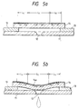
- each vibrating plate 24 is bent with the middle region toward the nozzle 22 as shown in Fig. 7 thereby pressuring the ink in that region and ejecting it in the form of ink droplets through the nozzle 22.
- a third embodiment shown in Fig. 8 has positively and negatively polarized comb-type electrodes 37, 38 formed on both upper and lower surfaces so as to face each other across a vibrating plate 34. That is, on an upper surface 34a opposite to a nozzle plate 31 of the vibrating plate 34 are both comb-type electrodes 37a, 38a formed at both ends, whereas on the lower surface 34b facing the nozzle plate 31 are both comb-type electrodes 37b, 38b patterned at the middle region, as shown in Fig. 8b. These electrodes 37b, 38b are connected to the electrodes 37a, 38a through an end surface 34c of the vibrating plate 34.
- the comb-type electrodes 37a, 38a at both end regions cause such regions of the upper surface 34a to be elongated while the electrodes 37b, 38b at the middle region cause such region of the lower surface 34b to be elongated.
- the vibrating plate 34 is bent toward the nozzle 32.
- Fig. 9 shows a fourth embodiment in which each of vibrating plates is formed as a cantilever and has comb-type electrodes arranged on both surfaces thereof.
- each vibrating plate 44 On a gap plate 43 fixed on one surface of a nozzle plate 41 is the base end of each vibrating plate 44 that extends so that its free end covers a nozzle 42.
- On the vibrating plate 44 are a pair of positive and negative comb-type electrodes 47a, 48a on an upper surface 44a opposite to the nozzle plate 41 so that these electrodes face each other across the vibrating plate.
- Further, on the lower surface 44b facing the nozzle plate are comb-type electrodes 47b, 48b formed so that their teeth are meshed with each other along the vibrating plate 44 as shown in Fig. 9b. These electrodes 47b, 48b are connected to the electrodes 47a, 48a through an end surface 44c of vibrating plate 44.
- the vibrating plate 44 is bent with its free end bowed toward the nozzle 42 to thereby pressure the ink present between the nozzle plate 41 and the vibrating plate 44 and eject the pressured ink in the form of ink droplets through the nozzle 42.
- Figures 9a and 9b show the comb-type electrodes 47, 48 formed on both upper and lower surfaces of each cantilever-type vibrating plate 44.
- the advantage similar to that described above may be provided by forming the comb-type electrodes 47, 48 only on the upper surface 44a opposite to the nozzle plate 41.
- a fifth embodiment which is shown in Fig. 11 et . seq . has each nozzle formed on each vibrating plate itself to make the recording head simpler and thinner in design.
- the recording head 50 comprises a frame 51 and an ink pressuring member 55 fixed on the frame.
- the frame 51 is formed as a plate-like block that is E-shaped in cross section extending in the direction of arraying the nozzles 52.
- projections 51a supporting the ink pressuring member 55.
- there is formed integrally with frame 51 a gap forming projection 51c that creates a gap of about 10 ⁇ m together with the vibrating plate 54.
- the ink pressuring member 55 comprises a plurality of vibrating plates 54 separated from each other by slits 56. On each vibrating plate 54 is a nozzle 52 arranged at the middle in the longitudinal direction thereof.
- each vibrating plate 54 has a positive comb-type electrode 57 connected to an individual signal electrode 57c and a negative comb-type electrode 58 connected to the common electrode 58c on a surface 54a that does not come in contact with the ink.
- These comb-type electrodes 57, 58 are formed so that one or more comb tooth-like electrodes extending inward from both ends of the vibrating plate 54 can be meshed at the middle region Lc where a nozzle 52 is formed.
- reference numeral 59 designates a seal body made of a soft resin material bonded on the upper surface of the ink pressuring member 55 to prevent leakage of the ink from the slits 56.
- This seal body 59 is provided with holes 59a not to hinder the ejection of ink from the nozzles 52.
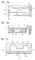
- the respective comb-type electrode 57, 58 on the vibrating plates 54 connected to these common and signal electrodes cause these selected vibrating plates 54 to be bent toward the gap forming projection 51c as shown in Fig. 13 thereby to increase the pressure on the ink on the periphery of the gap forming projection 51c and eject the pressured ink toward a recording sheet from the nozzles of these selected vibrating plates 54.
- Fig. 12b shows another embodiment of the electrode pattern to be formed on each vibrating plate.
- a positive comb-type electrode 67 and a negative comb-like electrode 68 are formed so as to face each other on both ends except for the middle region Lc of each vibrating plate 64 where a nozzle 62 is formed.
- each vibrating plate 54 having the nozzle 52 is separated by the slits 56 so as to allow the vibrating plates to operate independently of each other.
- Fig. 14 shows a sixth embodiment so constructed that only selected nozzle forming portions can be deformed using a single ink pressuring member.
- An ink pressuring member 75 fixed on supporting projected groove portions 71a of a frame 71 is made up of a plate body formed of a single piezoelectric material.
- On ink pressuring member 75 are a plurality of nozzles 72 arrayed in a direction along a gap forming projected groove portion 71c located at the middle of the frame 71.
- On an upper surface 75a that does not come in contact with the ink pressuring member 53 are a positive annular comb-type electrode 77 connected to an individual signal electrode 77c and a negative electrode 78 formed concentrically with each nozzle 72 so as to surround the nozzle 72.
- both annular comb-type electrodes 77, 78 Upon application of a voltage across the selected one or more signal electrodes 77c and a common electrode 78c, both annular comb-type electrodes 77, 78 cause a middle region Lc surrounding the corresponding nozzles 72 to be bent toward the gap forming projected groove portion 71c, thereby pressuring the ink in that region and ejecting the pressured ink in the form of ink droplets through the corresponding nozzles 72.
Landscapes
- Particle Formation And Scattering Control In Inkjet Printers (AREA)
Claims (10)
- Tête d'enregistrement d'imprimante à jet d'encre comprenant deux éléments face à face (11, 14 ; 21, 24), avec un petit espace entre ceux-ci pour y introduire une partie de l'encre, un desdits deux éléments (14 ; 24) étant constitué d'un matériau piézoélectrique pour former un élément de mise sous pression de l'encre, dans laquelle un desdits éléments (11 ; 21) est pourvu d'un ajutage d'éjection d'encre (12 ; 22), caractérisée en ce qu'au moins une surface (14a ; 24a, 24b) dudit élément est pourvue d'une paire d'électrodes de type peigne polarisées positivement et négativement (17, 18 ; 27a, 28a, 27b, 28b).
- Tête d'enregistrement d'imprimante à jet d'encre selon la revendication 1, dans laquelle l'un desdits éléments constituant l'élément de mise sous pression de l'encre est pourvu de l'ajutage d'éjection d'encre (52) et une surface dudit élément est pourvue de la paire d'électrodes de type peigne polarisées positivement et négativement (57, 58).
- Tête d'enregistrement d'imprimante à jet d'encre selon la revendication 2, dans laquelle ladite surface dudit élément de mise sous pression de l'encre (71) est pourvue d'une paire d'électrodes de type peigne annulaires polarisées positivement et négativement (77, 78) de manière à ce qu'elles entourent ledit ajutage (72).
- Tête d'enregistrement d'imprimante à jet d'encre selon l'une quelconque des revendications 2 et 3, dans laquelle ledit élément de mise sous pression de l'encre (50) est pourvu d'une pluralité de fentes (56) pour former une pluralité de compartiments, composés chacun d'une bande comportant dessus un ajutage (52), et dans laquelle une surface de chaque bande (54) est pourvue d'une paire d'électrodes de type peigne polarisées positivement et négativement.
- Tête d'enregistrement d'imprimante à jet d'encre selon l'une quelconque des revendications 2 à 4, comprenant en outre une partie saillante de formation d'espace (51 ; 71c) qui est prévue à l'opposé dudit ajutage d'éjection d'encre (52 ; 72).
- Tête d'enregistrement d'imprimante à jet d'encre (10) selon la revendication 1, comprenant deux éléments face à face (11, 14 ; 21, 24), avec un petit espace entre ceux-ci pour y introduire une partie de l'encre, un desdits deux éléments (11 ; 21) étant pourvu d'un ajutage d'éjection d'encre (12 ; 22) et l'autre (14 ; 24) desdits deux éléments étant constitué d'un matériau piézoélectrique pour servir d'élément de mise sous pression de l'encre, dans laquelle au moins une surface (14a ; 24a, 24b) dudit élément de mise sous pression de l'encre est pourvue d'une paire d'électrodes de type peigne polarisées positivement et négativement (17, 18 ; 27a, 28a, 27b, 28b), de telle sorte qu'une tension appliquée entre lesdites deux électrodes déforme ledit élément de mise sous pression de l'encre vers ledit ajutage (12 ; 22), ce qui éjecte des gouttelettes d'encre par ledit ajutage (12 ; 22).
- Tête d'enregistrement d'imprimante à jet d'encre (10) selon la revendication 6, dans laquelle seule une surface dudit élément de mise sous pression de l'encre est pourvue d'une paire d'électrodes de type peigne polarisées positivement et négativement (17, 18).
- Tête d'enregistrement d'imprimante à jet d'encre selon la revendication 6, dans laquelle la surface supérieure et la surface inférieure dudit élément de mise sous pression de l'encre (21) sont toutes les deux pourvues d'une paire d'électrodes de type peigne polarisées positivement et négativement (27a, 28a, 27b, 28b).
- Tête d'enregistrement d'imprimante à jet d'encre selon l'une quelconque des revendications 6 à 8, dans laquelle une partie (Lc) d'une surface dudit élément de mise sous pression de l'encre (14) correspondant à une position où est disposé un ajutage (12) est pourvue d'une paire d'électrodes de type peigne polarisées positivement et négativement ayant une première orientation, et les autres parties (Ls) de ladite surface dudit élément de mise sous pression de l'encre sont pourvues d'une paire d'électrodes de type peigne polarisées positivement et négativement ayant une seconde orientation.
- Tête d'enregistrement d'imprimante à jet d'encre selon l'une quelconque des revendications 6 à 9, dans laquelle ledit élément de mise sous pression de l'encre (44) est d'un type console.
Applications Claiming Priority (8)
| Application Number | Priority Date | Filing Date | Title |
|---|---|---|---|
| JP22977189 | 1989-09-05 | ||
| JP229771/89 | 1989-09-05 | ||
| JP234894/89 | 1989-09-11 | ||
| JP23489389 | 1989-09-11 | ||
| JP234893/89 | 1989-09-11 | ||
| JP23489489 | 1989-09-11 | ||
| JP24115489 | 1989-09-18 | ||
| JP241154/89 | 1989-09-18 |
Publications (3)
| Publication Number | Publication Date |
|---|---|
| EP0416540A2 EP0416540A2 (fr) | 1991-03-13 |
| EP0416540A3 EP0416540A3 (en) | 1991-06-12 |
| EP0416540B1 true EP0416540B1 (fr) | 1994-12-14 |
Family
ID=27477383
Family Applications (1)
| Application Number | Title | Priority Date | Filing Date |
|---|---|---|---|
| EP90116978A Expired - Lifetime EP0416540B1 (fr) | 1989-09-05 | 1990-09-04 | Tête d'impression pour imprimante à jet d'encre |
Country Status (4)
| Country | Link |
|---|---|
| US (1) | US5255016A (fr) |
| EP (1) | EP0416540B1 (fr) |
| DE (1) | DE69015062T2 (fr) |
| HK (1) | HK93697A (fr) |
Cited By (1)
| Publication number | Priority date | Publication date | Assignee | Title |
|---|---|---|---|---|
| US9028048B2 (en) | 2000-05-23 | 2015-05-12 | Memjet Technology Ltd. | Printhead assembly incorporating ink distribution assembly |
Families Citing this family (104)
| Publication number | Priority date | Publication date | Assignee | Title |
|---|---|---|---|---|
| US5202703A (en) * | 1990-11-20 | 1993-04-13 | Spectra, Inc. | Piezoelectric transducers for ink jet systems |
| JPH05177834A (ja) * | 1991-06-04 | 1993-07-20 | Seiko Epson Corp | インクジェット記録ヘッド |
| JPH05124186A (ja) * | 1991-11-06 | 1993-05-21 | Brother Ind Ltd | 液滴噴射装置 |
| JP3317308B2 (ja) * | 1992-08-26 | 2002-08-26 | セイコーエプソン株式会社 | 積層型インクジェット記録ヘッド、及びその製造方法 |
| US6601949B1 (en) | 1992-08-26 | 2003-08-05 | Seiko Epson Corporation | Actuator unit for ink jet recording head |
| JP3637633B2 (ja) * | 1995-05-10 | 2005-04-13 | ブラザー工業株式会社 | インクジェット式印字ヘッド及びその製造方法 |
| EP0785071B1 (fr) * | 1995-07-24 | 1999-10-13 | Seiko Epson Corporation | Puce du type a couche piezo-electrique/electrostrictive |
| JPH0985946A (ja) * | 1995-09-25 | 1997-03-31 | Sharp Corp | インクジェットヘッド及びその製造方法 |
| JP3517535B2 (ja) * | 1996-07-10 | 2004-04-12 | 日本碍子株式会社 | 表示装置 |
| US6002549A (en) * | 1996-11-01 | 1999-12-14 | Seagate Technology, Inc. | Dither microactors for stiction release in magnetic disc drives |
| WO1998020486A1 (fr) | 1996-11-01 | 1998-05-14 | Seagate Technology, Inc. | Bras de commande a microcommande piezoelectrique integree |
| USRE38340E1 (en) * | 1996-11-04 | 2003-12-02 | Seagate Technology Llc | Multi-point bending of bars during fabrication of magnetic recording heads |
| US6091182A (en) * | 1996-11-07 | 2000-07-18 | Ngk Insulators, Ltd. | Piezoelectric/electrostrictive element |
| WO1998027547A1 (fr) * | 1996-12-16 | 1998-06-25 | Seagate Technology, Inc. | Tete de micro-organe d'actionnement piezo-electrique dimorphe et ensemble de flexion |
| KR20010005858A (ko) | 1997-03-31 | 2001-01-15 | 시게이트 테크놀로지 엘엘씨 | 요곡부가 구비된 마이크로 액추에이터 |
| US6023963A (en) * | 1997-04-24 | 2000-02-15 | Seagate Technology, Inc. | Single-sided sensor for glide height testing |
| US6396667B1 (en) | 1997-06-24 | 2002-05-28 | Seagate Technology Llc | Electromagnetic disc drive microactuator and suspension |
| US6712453B2 (en) | 1997-07-15 | 2004-03-30 | Silverbrook Research Pty Ltd. | Ink jet nozzle rim |
| US6935724B2 (en) | 1997-07-15 | 2005-08-30 | Silverbrook Research Pty Ltd | Ink jet nozzle having actuator with anchor positioned between nozzle chamber and actuator connection point |
| US6855264B1 (en) | 1997-07-15 | 2005-02-15 | Kia Silverbrook | Method of manufacture of an ink jet printer having a thermal actuator comprising an external coil spring |
| US6648453B2 (en) | 1997-07-15 | 2003-11-18 | Silverbrook Research Pty Ltd | Ink jet printhead chip with predetermined micro-electromechanical systems height |
| US6550896B2 (en) * | 1997-07-15 | 2003-04-22 | Silverbrook Research Pty Ltd | Nozzle arrangement for an ink jet printhead that includes a shape memory actuator |
| US6682174B2 (en) | 1998-03-25 | 2004-01-27 | Silverbrook Research Pty Ltd | Ink jet nozzle arrangement configuration |
| US7195339B2 (en) | 1997-07-15 | 2007-03-27 | Silverbrook Research Pty Ltd | Ink jet nozzle assembly with a thermal bend actuator |
| US6402300B1 (en) | 1997-07-15 | 2002-06-11 | Silverbrook Research Pty. Ltd. | Ink jet nozzle assembly including meniscus pinning of a fluidic seal |
| US7465030B2 (en) | 1997-07-15 | 2008-12-16 | Silverbrook Research Pty Ltd | Nozzle arrangement with a magnetic field generator |
| US20080316264A1 (en) * | 1997-07-15 | 2008-12-25 | Silverbrook Research Pty Ltd | Printhead integrated circuit with nozzles in thin surface layer |
| US6447100B2 (en) * | 1997-07-15 | 2002-09-10 | Silverbrook Research Pty Ltd | Nozzle arrangement for an ink jet printhead which includes a refill actuator |
| US6485123B2 (en) | 1997-07-15 | 2002-11-26 | Silverbrook Research Pty Ltd | Shutter ink jet |
| US6217153B1 (en) * | 1997-07-15 | 2001-04-17 | Silverbrook Research Pty Ltd | Single bend actuator cupped paddle ink jet printing mechanism |
| US6412914B1 (en) * | 1997-07-15 | 2002-07-02 | Silverbrook Research Pty Ltd | Nozzle arrangement for an ink jet printhead that includes a hinged actuator |
| AUPP398798A0 (en) * | 1998-06-09 | 1998-07-02 | Silverbrook Research Pty Ltd | Image creation method and apparatus (ij43) |
| AUPO800497A0 (en) | 1997-07-15 | 1997-08-07 | Silverbrook Research Pty Ltd | Image creation method and apparatus (IJ26) |
| US7337532B2 (en) | 1997-07-15 | 2008-03-04 | Silverbrook Research Pty Ltd | Method of manufacturing micro-electromechanical device having motion-transmitting structure |
| US7527357B2 (en) | 1997-07-15 | 2009-05-05 | Silverbrook Research Pty Ltd | Inkjet nozzle array with individual feed channel for each nozzle |
| US7468139B2 (en) | 1997-07-15 | 2008-12-23 | Silverbrook Research Pty Ltd | Method of depositing heater material over a photoresist scaffold |
| US7556356B1 (en) | 1997-07-15 | 2009-07-07 | Silverbrook Research Pty Ltd | Inkjet printhead integrated circuit with ink spread prevention |
| US7022250B2 (en) | 1997-07-15 | 2006-04-04 | Silverbrook Research Pty Ltd | Method of fabricating an ink jet printhead chip with differential expansion actuators |
| US6247792B1 (en) * | 1997-07-15 | 2001-06-19 | Silverbrook Research Pty Ltd | PTFE surface shooting shuttered oscillating pressure ink jet printing mechanism |
| US6557977B1 (en) * | 1997-07-15 | 2003-05-06 | Silverbrook Research Pty Ltd | Shape memory alloy ink jet printing mechanism |
| US6682176B2 (en) * | 1997-07-15 | 2004-01-27 | Silverbrook Research Pty Ltd | Ink jet printhead chip with nozzle arrangements incorporating spaced actuating arms |
| US6986202B2 (en) | 1997-07-15 | 2006-01-17 | Silverbrook Research Pty Ltd. | Method of fabricating a micro-electromechanical fluid ejection device |
| US6866290B2 (en) * | 2002-12-04 | 2005-03-15 | James Tsai | Apparatus of a collapsible handcart for turning a platform when operating a retractable handle |
| US6488359B2 (en) * | 1997-07-15 | 2002-12-03 | Silverbrook Research Pty Ltd | Ink jet printhead that incorporates through-chip ink ejection nozzle arrangements |
| US6425651B1 (en) * | 1997-07-15 | 2002-07-30 | Silverbrook Research Pty Ltd | High-density inkjet nozzle array for an inkjet printhead |
| US7497555B2 (en) | 1998-07-10 | 2009-03-03 | Silverbrook Research Pty Ltd | Inkjet nozzle assembly with pre-shaped actuator |
| US6362542B1 (en) | 1997-08-15 | 2002-03-26 | Seagate Technology Llc | Piezoelectric microactuator for precise head positioning |
| US6269687B1 (en) | 1997-09-22 | 2001-08-07 | Seagate Technology Llc | Force sensing slider |
| US6273342B1 (en) * | 1997-10-06 | 2001-08-14 | Omron Corporation | Atomizer |
| US6067215A (en) | 1997-10-09 | 2000-05-23 | Seagate Technology, Inc. | Magnetic shielding for electromagnetic microactuator |
| US6163434A (en) * | 1997-10-23 | 2000-12-19 | Seagate Technology Llc | Piezoresistive position sensors embedded in disc drive microactuator |
| US6435667B1 (en) * | 1997-12-12 | 2002-08-20 | Silverbrook Research Pty Ltd. | Opposed ejection ports and ink inlets in an ink jet printhead chip |
| US6157522A (en) * | 1998-04-07 | 2000-12-05 | Seagate Technology Llc | Suspension-level microactuator |
| US6215629B1 (en) | 1998-04-16 | 2001-04-10 | Seagate Technology Llc | Unitary synchronous flexure microactuator |
| US6078473A (en) * | 1998-05-13 | 2000-06-20 | Seagate Technology, Inc. | Gimbal flexure for use with microactuator |
| US6439695B2 (en) * | 1998-06-08 | 2002-08-27 | Silverbrook Research Pty Ltd | Nozzle arrangement for an ink jet printhead including volume-reducing actuators |
| US6959982B2 (en) * | 1998-06-09 | 2005-11-01 | Silverbrook Research Pty Ltd | Flexible wall driven inkjet printhead nozzle |
| US6414822B1 (en) | 1998-06-11 | 2002-07-02 | Seagate Technology Llc | Magnetic microactuator |
| US6359758B1 (en) | 1998-06-11 | 2002-03-19 | Seagate Technology, Llc | Rigid body microactuator having elastic joint attachment |
| JP3262078B2 (ja) * | 1998-09-08 | 2002-03-04 | 日本電気株式会社 | インクジェット記録ヘッド |
| AUPP702098A0 (en) | 1998-11-09 | 1998-12-03 | Silverbrook Research Pty Ltd | Image creation method and apparatus (ART73) |
| US6742873B1 (en) * | 2001-04-16 | 2004-06-01 | Silverbrook Research Pty Ltd | Inkjet printhead construction |
| GB9820755D0 (en) | 1998-09-23 | 1998-11-18 | Xaar Technology Ltd | Drop on demand ink jet printing apparatus |
| US6233124B1 (en) | 1998-11-18 | 2001-05-15 | Seagate Technology Llc | Piezoelectric microactuator suspension assembly with improved stroke length |
| US6268984B1 (en) | 1999-01-22 | 2001-07-31 | Seagate Technology Llc | Magnet configuration for head-level microactuator |
| US6557970B2 (en) | 2000-05-23 | 2003-05-06 | Silverbrook Research Pty Ltd | Nozzle guard for a printhead |
| ATE367266T1 (de) * | 2000-05-24 | 2007-08-15 | Silverbrook Res Pty Ltd | Herstellungsverfahren für einen tintenstrahldruckkopf mit bewegender düse und externem betätiger |
| SG153634A1 (en) * | 2000-05-24 | 2009-07-29 | Silverbrook Res Pty Ltd | Ink jet nozzle assembly with externally arranged nozzle actuator |
| IL153028A (en) | 2000-05-24 | 2005-06-19 | Silverbrook Res Pty Ltd | Ink jet printhead having a moving nozzle with an externally arranged actuator |
| AU2005200212B2 (en) * | 2000-05-24 | 2006-03-16 | Silverbrook Research Pty Ltd | Ink jet nozzle assembly with externally arranged nozzle actuator |
| US6474785B1 (en) | 2000-09-05 | 2002-11-05 | Hewlett-Packard Company | Flextensional transducer and method for fabrication of a flextensional transducer |
| JP3821095B2 (ja) * | 2000-10-05 | 2006-09-13 | オムロンヘルスケア株式会社 | 液体噴霧装置 |
| US6474787B2 (en) | 2001-03-21 | 2002-11-05 | Hewlett-Packard Company | Flextensional transducer |
| US6540339B2 (en) | 2001-03-21 | 2003-04-01 | Hewlett-Packard Company | Flextensional transducer assembly including array of flextensional transducers |
| US6712455B2 (en) * | 2001-03-30 | 2004-03-30 | Philip Morris Incorporated | Piezoelectrically driven printhead array |
| US6428140B1 (en) | 2001-09-28 | 2002-08-06 | Hewlett-Packard Company | Restriction within fluid cavity of fluid drop ejector |
| US6685302B2 (en) | 2001-10-31 | 2004-02-03 | Hewlett-Packard Development Company, L.P. | Flextensional transducer and method of forming a flextensional transducer |
| WO2003053496A2 (fr) * | 2001-12-19 | 2003-07-03 | Ran Yaron | Systeme de refrigeration miniature pour catheter d'exerese par voie cryothermique |
| US7025442B2 (en) * | 2002-02-11 | 2006-04-11 | Ran Yaron | Laser ink jet printer |
| US6527368B1 (en) | 2002-04-30 | 2003-03-04 | Hewlett-Packard Company | Layer with discontinuity over fluid slot |
| JP2004136461A (ja) * | 2002-10-15 | 2004-05-13 | Brother Ind Ltd | 液体圧力発生機構 |
| EP1481804A1 (fr) | 2003-05-28 | 2004-12-01 | F.Hoffmann-La Roche Ag | Dispositif de distribution de gouttes de liquide |
| JP2005014305A (ja) * | 2003-06-24 | 2005-01-20 | Brother Ind Ltd | 液滴噴射装置 |
| GB0620214D0 (en) * | 2006-10-12 | 2006-11-22 | The Technology Partnership Plc | Liquid projection apparatus |
| GB0620211D0 (en) * | 2006-10-12 | 2006-11-22 | The Technology Partnership Plc | Liquid projection apparatus |
| US7786653B2 (en) * | 2007-07-03 | 2010-08-31 | Northrop Grumman Systems Corporation | MEMS piezoelectric switch |
| US7946687B2 (en) * | 2008-05-05 | 2011-05-24 | Silverbrook Research Pty Ltd | Thermal bend actuator comprising bent active beam having resistive heating bars |
| US8226213B2 (en) * | 2008-05-05 | 2012-07-24 | Zamtec Limited | Short pulsewidth actuation of thermal bend actuator |
| DE102009002631B4 (de) * | 2009-04-24 | 2015-08-20 | Michael Förg | Piezoelektrischer Antrieb und Mikroventil mit einem solchen |
| WO2011053320A1 (fr) * | 2009-10-30 | 2011-05-05 | Hewlett-Packard Development Company, L.P. | Actionneur piézoélectrique comportant des électrodes incorporées |
| GB0922371D0 (en) | 2009-12-22 | 2010-02-03 | The Technology Partnership Plc | Printhead |
| US20120069099A1 (en) * | 2010-09-16 | 2012-03-22 | Huffman James D | Transducer having an improved electric field |
| DE102013105557B4 (de) * | 2013-05-29 | 2015-06-11 | Michael Förg | Piezoelektrischer Aktor |
| DE102013210561B4 (de) * | 2013-06-06 | 2016-11-10 | Albert-Ludwig-Universität Freiburg | Biegewandler mit einem piezoelektrischen Element |
| DE102013013402A1 (de) * | 2013-08-02 | 2015-02-19 | Fraunhofer-Gesellschaft zur Förderung der angewandten Forschung e.V | Biegeelementanordnung sowie deren Verwendung |
| JP6518417B2 (ja) * | 2014-09-01 | 2019-05-22 | 東芝テック株式会社 | 液体循環装置 |
| CN113386465B (zh) | 2016-12-19 | 2023-06-13 | 富士胶卷迪马蒂克斯股份有限公司 | 流体输送系统的致动器 |
| ES2983011T3 (es) * | 2018-07-20 | 2024-10-21 | Ricoh Co Ltd | Dispositivo de formación de gotas, método de formación de gotas y aparato dispensador |
| CN111439034B (zh) | 2020-05-13 | 2025-04-25 | 苏州锐发打印技术有限公司 | 压电板带通孔的压电喷墨打印器件 |
| CN111439033B (zh) | 2020-05-13 | 2025-04-25 | 苏州锐发打印技术有限公司 | 带有外表面电极层的压电喷墨打印器件 |
| CN111923600B (zh) | 2020-05-13 | 2021-10-22 | 苏州锐发打印技术有限公司 | 带有内表面电极层的压电喷墨打印器件 |
| CN111660671B (zh) | 2020-05-13 | 2025-04-25 | 苏州锐发打印技术有限公司 | 用多种墨水的压电喷墨打印头及打印系统 |
| CN111703207B (zh) | 2020-05-13 | 2021-09-14 | 苏州锐发打印技术有限公司 | 带单层内电极的压电喷墨打印器件 |
| CN111532027B (zh) | 2020-05-13 | 2025-04-25 | 苏州锐发打印技术有限公司 | 压电喷墨打印头及打印系统 |
Citations (1)
| Publication number | Priority date | Publication date | Assignee | Title |
|---|---|---|---|---|
| FR2314832A1 (fr) * | 1975-06-20 | 1977-01-14 | Siemens Ag | Appareil enregistreur fonctionnant par projection de gouttelettes de liquide |
Family Cites Families (14)
| Publication number | Priority date | Publication date | Assignee | Title |
|---|---|---|---|---|
| JPS5583274A (en) * | 1978-12-20 | 1980-06-23 | Toshiba Corp | Piezo-electric sheet and method of fabricating the same |
| US4381469A (en) * | 1979-07-20 | 1983-04-26 | Murata Manufacturing Company, Ltd. | Temperature stable piezoelectric device |
| US4383264A (en) * | 1980-06-18 | 1983-05-10 | Exxon Research And Engineering Co. | Demand drop forming device with interacting transducer and orifice combination |
| EP0095911B1 (fr) * | 1982-05-28 | 1989-01-18 | Xerox Corporation | Disposition d'éjection de gouttelettes par onde de pression et ensemble |
| US4469976A (en) * | 1982-07-06 | 1984-09-04 | The United States Of America As Represented By The Secretary Of The Navy | Single-side connected transducer |
| US4516140A (en) * | 1983-12-27 | 1985-05-07 | At&T Teletype Corporation | Print head actuator for an ink jet printer |
| JPS612376A (ja) * | 1984-06-14 | 1986-01-08 | Ngk Spark Plug Co Ltd | シ−ト状圧電体 |
| DE3618107A1 (de) * | 1986-05-30 | 1987-12-03 | Siemens Ag | Tintenschreibkopf mit piezoelektrisch anregbarer membran |
| US4879568A (en) * | 1987-01-10 | 1989-11-07 | Am International, Inc. | Droplet deposition apparatus |
| JPS6372172A (ja) * | 1987-03-11 | 1988-04-01 | Ngk Spark Plug Co Ltd | 薄板状電歪積層体 |
| JP2676085B2 (ja) * | 1988-08-26 | 1997-11-12 | 株式会社 半導体エネルギー研究所 | プラズマ処理装置およびプラズマ処理方法 |
| US4825227A (en) * | 1988-02-29 | 1989-04-25 | Spectra, Inc. | Shear mode transducer for ink jet systems |
| EP0337429B1 (fr) * | 1988-04-12 | 1993-07-07 | Seiko Epson Corporation | Tête à jet d'encre |
| JPH02269058A (ja) * | 1989-03-14 | 1990-11-02 | Seiko Epson Corp | レーリーモード弾性表面波による液滴ジェット装置 |
-
1990
- 1990-08-27 US US07/572,529 patent/US5255016A/en not_active Expired - Fee Related
- 1990-09-04 EP EP90116978A patent/EP0416540B1/fr not_active Expired - Lifetime
- 1990-09-04 DE DE69015062T patent/DE69015062T2/de not_active Expired - Fee Related
-
1997
- 1997-06-26 HK HK93697A patent/HK93697A/en not_active IP Right Cessation
Patent Citations (1)
| Publication number | Priority date | Publication date | Assignee | Title |
|---|---|---|---|---|
| FR2314832A1 (fr) * | 1975-06-20 | 1977-01-14 | Siemens Ag | Appareil enregistreur fonctionnant par projection de gouttelettes de liquide |
Non-Patent Citations (1)
| Title |
|---|
| IBM TECHNICAL DISCLOSURE BULLETIN, vol. 22, no. 6, NEW YORK US; pages 2527-2529; K.K. SHIH & H.C. WANG: "Application of GMO as an active element to printing mechanism". * |
Cited By (2)
| Publication number | Priority date | Publication date | Assignee | Title |
|---|---|---|---|---|
| US9028048B2 (en) | 2000-05-23 | 2015-05-12 | Memjet Technology Ltd. | Printhead assembly incorporating ink distribution assembly |
| US9254655B2 (en) | 2000-05-23 | 2016-02-09 | Memjet Technology Ltd. | Inkjet printer having laminated stack for receiving ink from ink distribution molding |
Also Published As
| Publication number | Publication date |
|---|---|
| EP0416540A2 (fr) | 1991-03-13 |
| DE69015062D1 (de) | 1995-01-26 |
| US5255016A (en) | 1993-10-19 |
| EP0416540A3 (en) | 1991-06-12 |
| DE69015062T2 (de) | 1995-05-04 |
| HK93697A (en) | 1997-08-01 |
Similar Documents
| Publication | Publication Date | Title |
|---|---|---|
| US5255016A (en) | Ink jet printer recording head | |
| EP0402172B1 (fr) | Tête pour imprimante à jet d'encre | |
| US5359354A (en) | Ink jet head with dummy slots | |
| US5992978A (en) | Ink jet recording apparatus, and an ink jet head manufacturing method | |
| US5424769A (en) | Ink jet recording head | |
| HK1006559B (en) | Ink jet recording head | |
| JPH0811304A (ja) | インクジェットヘッド | |
| EP1083048A1 (fr) | Tete d'ecriture a jet d'encre et procede de fabrication associe | |
| JPH0224223B2 (fr) | ||
| JP2881616B2 (ja) | インクジェット式ヘッド装置 | |
| US6299295B1 (en) | Ink jet printing head having ink chambers arranged in succession by lamination | |
| JP3125299B2 (ja) | インクジェットプリンタ用の記録ヘッド | |
| JPH02187352A (ja) | インクジェットヘッド | |
| JPH0757545B2 (ja) | インクジェットヘッド及びその製造方法 | |
| JP3257140B2 (ja) | インクジェット記録装置 | |
| JPH0825627A (ja) | インクジェットヘッドおよびその製造方法 | |
| JP3341911B2 (ja) | インクジェット式印字ヘッド | |
| JP3465959B2 (ja) | インクジェットヘッド | |
| JPH05318727A (ja) | インクジェット式印字ヘッド駆動方法 | |
| JP3064455B2 (ja) | インクジェットヘッド | |
| EP0541294B1 (fr) | Dispositif d'éjection de gouttelettes | |
| JP3454841B2 (ja) | インクジェットヘッド | |
| JP2785720B2 (ja) | インクジェット式印字ヘッド | |
| JPH03227247A (ja) | インクジェット記録装置 | |
| JPH04347643A (ja) | インクジェットヘッド |
Legal Events
| Date | Code | Title | Description |
|---|---|---|---|
| PUAI | Public reference made under article 153(3) epc to a published international application that has entered the european phase |
Free format text: ORIGINAL CODE: 0009012 |
|
| AK | Designated contracting states |
Kind code of ref document: A2 Designated state(s): DE FR GB |
|
| PUAL | Search report despatched |
Free format text: ORIGINAL CODE: 0009013 |
|
| AK | Designated contracting states |
Kind code of ref document: A3 Designated state(s): DE FR GB |
|
| 17P | Request for examination filed |
Effective date: 19910918 |
|
| 17Q | First examination report despatched |
Effective date: 19930324 |
|
| GRAA | (expected) grant |
Free format text: ORIGINAL CODE: 0009210 |
|
| AK | Designated contracting states |
Kind code of ref document: B1 Designated state(s): DE FR GB |
|
| REF | Corresponds to: |
Ref document number: 69015062 Country of ref document: DE Date of ref document: 19950126 |
|
| ET | Fr: translation filed | ||
| PLBE | No opposition filed within time limit |
Free format text: ORIGINAL CODE: 0009261 |
|
| STAA | Information on the status of an ep patent application or granted ep patent |
Free format text: STATUS: NO OPPOSITION FILED WITHIN TIME LIMIT |
|
| 26N | No opposition filed | ||
| PGFP | Annual fee paid to national office [announced via postgrant information from national office to epo] |
Ref country code: GB Payment date: 19970826 Year of fee payment: 8 |
|
| PGFP | Annual fee paid to national office [announced via postgrant information from national office to epo] |
Ref country code: FR Payment date: 19970909 Year of fee payment: 8 |
|
| PGFP | Annual fee paid to national office [announced via postgrant information from national office to epo] |
Ref country code: DE Payment date: 19970912 Year of fee payment: 8 |
|
| PG25 | Lapsed in a contracting state [announced via postgrant information from national office to epo] |
Ref country code: GB Free format text: LAPSE BECAUSE OF NON-PAYMENT OF DUE FEES Effective date: 19980904 |
|
| GBPC | Gb: european patent ceased through non-payment of renewal fee |
Effective date: 19980904 |
|
| PG25 | Lapsed in a contracting state [announced via postgrant information from national office to epo] |
Ref country code: FR Free format text: LAPSE BECAUSE OF NON-PAYMENT OF DUE FEES Effective date: 19990531 |
|
| PG25 | Lapsed in a contracting state [announced via postgrant information from national office to epo] |
Ref country code: DE Free format text: LAPSE BECAUSE OF NON-PAYMENT OF DUE FEES Effective date: 19990701 |
|
| REG | Reference to a national code |
Ref country code: FR Ref legal event code: ST |