EP0416832B1 - Dispositif de formation de l'image - Google Patents
Dispositif de formation de l'image Download PDFInfo
- Publication number
- EP0416832B1 EP0416832B1 EP90309596A EP90309596A EP0416832B1 EP 0416832 B1 EP0416832 B1 EP 0416832B1 EP 90309596 A EP90309596 A EP 90309596A EP 90309596 A EP90309596 A EP 90309596A EP 0416832 B1 EP0416832 B1 EP 0416832B1
- Authority
- EP
- European Patent Office
- Prior art keywords
- resolution
- signal
- light beam
- image
- image forming
- Prior art date
- Legal status (The legal status is an assumption and is not a legal conclusion. Google has not performed a legal analysis and makes no representation as to the accuracy of the status listed.)
- Expired - Lifetime
Links
Images






Classifications
-
- H—ELECTRICITY
- H04—ELECTRIC COMMUNICATION TECHNIQUE
- H04N—PICTORIAL COMMUNICATION, e.g. TELEVISION
- H04N1/00—Scanning, transmission or reproduction of documents or the like, e.g. facsimile transmission; Details thereof
- H04N1/04—Scanning arrangements, i.e. arrangements for the displacement of active reading or reproducing elements relative to the original or reproducing medium, or vice versa
- H04N1/0402—Scanning different formats; Scanning with different densities of dots per unit length, e.g. different numbers of dots per inch (dpi); Conversion of scanning standards
- H04N1/0405—Different formats, e.g. A3 and A4
-
- G—PHYSICS
- G06—COMPUTING OR CALCULATING; COUNTING
- G06K—GRAPHICAL DATA READING; PRESENTATION OF DATA; RECORD CARRIERS; HANDLING RECORD CARRIERS
- G06K15/00—Arrangements for producing a permanent visual presentation of the output data, e.g. computer output printers
- G06K15/02—Arrangements for producing a permanent visual presentation of the output data, e.g. computer output printers using printers
- G06K15/12—Arrangements for producing a permanent visual presentation of the output data, e.g. computer output printers using printers by photographic printing, e.g. by laser printers
- G06K15/1204—Arrangements for producing a permanent visual presentation of the output data, e.g. computer output printers using printers by photographic printing, e.g. by laser printers involving the fast moving of an optical beam in the main scanning direction
- G06K15/1219—Detection, control or error compensation of scanning velocity or position, e.g. synchronisation
-
- G—PHYSICS
- G06—COMPUTING OR CALCULATING; COUNTING
- G06K—GRAPHICAL DATA READING; PRESENTATION OF DATA; RECORD CARRIERS; HANDLING RECORD CARRIERS
- G06K15/00—Arrangements for producing a permanent visual presentation of the output data, e.g. computer output printers
- G06K15/02—Arrangements for producing a permanent visual presentation of the output data, e.g. computer output printers using printers
- G06K15/12—Arrangements for producing a permanent visual presentation of the output data, e.g. computer output printers using printers by photographic printing, e.g. by laser printers
- G06K15/1204—Arrangements for producing a permanent visual presentation of the output data, e.g. computer output printers using printers by photographic printing, e.g. by laser printers involving the fast moving of an optical beam in the main scanning direction
- G06K15/1223—Resolution control, enlarging or reducing, edge or detail enhancement
-
- H—ELECTRICITY
- H04—ELECTRIC COMMUNICATION TECHNIQUE
- H04N—PICTORIAL COMMUNICATION, e.g. TELEVISION
- H04N1/00—Scanning, transmission or reproduction of documents or the like, e.g. facsimile transmission; Details thereof
- H04N1/04—Scanning arrangements, i.e. arrangements for the displacement of active reading or reproducing elements relative to the original or reproducing medium, or vice versa
- H04N1/0402—Scanning different formats; Scanning with different densities of dots per unit length, e.g. different numbers of dots per inch (dpi); Conversion of scanning standards
-
- H—ELECTRICITY
- H04—ELECTRIC COMMUNICATION TECHNIQUE
- H04N—PICTORIAL COMMUNICATION, e.g. TELEVISION
- H04N1/00—Scanning, transmission or reproduction of documents or the like, e.g. facsimile transmission; Details thereof
- H04N1/04—Scanning arrangements, i.e. arrangements for the displacement of active reading or reproducing elements relative to the original or reproducing medium, or vice versa
- H04N1/0402—Scanning different formats; Scanning with different densities of dots per unit length, e.g. different numbers of dots per inch (dpi); Conversion of scanning standards
- H04N1/0408—Different densities of dots per unit length
- H04N1/0411—Different densities of dots per unit length in the main scanning direction
-
- H—ELECTRICITY
- H04—ELECTRIC COMMUNICATION TECHNIQUE
- H04N—PICTORIAL COMMUNICATION, e.g. TELEVISION
- H04N1/00—Scanning, transmission or reproduction of documents or the like, e.g. facsimile transmission; Details thereof
- H04N1/04—Scanning arrangements, i.e. arrangements for the displacement of active reading or reproducing elements relative to the original or reproducing medium, or vice versa
- H04N1/0402—Scanning different formats; Scanning with different densities of dots per unit length, e.g. different numbers of dots per inch (dpi); Conversion of scanning standards
- H04N1/042—Details of the method used
- H04N1/0443—Varying the scanning velocity or position
-
- H—ELECTRICITY
- H04—ELECTRIC COMMUNICATION TECHNIQUE
- H04N—PICTORIAL COMMUNICATION, e.g. TELEVISION
- H04N1/00—Scanning, transmission or reproduction of documents or the like, e.g. facsimile transmission; Details thereof
- H04N1/04—Scanning arrangements, i.e. arrangements for the displacement of active reading or reproducing elements relative to the original or reproducing medium, or vice versa
- H04N1/0402—Scanning different formats; Scanning with different densities of dots per unit length, e.g. different numbers of dots per inch (dpi); Conversion of scanning standards
- H04N1/042—Details of the method used
- H04N1/0446—Varying the modulation time or intensity
-
- H—ELECTRICITY
- H04—ELECTRIC COMMUNICATION TECHNIQUE
- H04N—PICTORIAL COMMUNICATION, e.g. TELEVISION
- H04N1/00—Scanning, transmission or reproduction of documents or the like, e.g. facsimile transmission; Details thereof
- H04N1/04—Scanning arrangements, i.e. arrangements for the displacement of active reading or reproducing elements relative to the original or reproducing medium, or vice versa
- H04N1/113—Scanning arrangements, i.e. arrangements for the displacement of active reading or reproducing elements relative to the original or reproducing medium, or vice versa using oscillating or rotating mirrors
- H04N1/1135—Scanning arrangements, i.e. arrangements for the displacement of active reading or reproducing elements relative to the original or reproducing medium, or vice versa using oscillating or rotating mirrors for the main-scan only
-
- H—ELECTRICITY
- H04—ELECTRIC COMMUNICATION TECHNIQUE
- H04N—PICTORIAL COMMUNICATION, e.g. TELEVISION
- H04N1/00—Scanning, transmission or reproduction of documents or the like, e.g. facsimile transmission; Details thereof
- H04N1/04—Scanning arrangements, i.e. arrangements for the displacement of active reading or reproducing elements relative to the original or reproducing medium, or vice versa
- H04N1/12—Scanning arrangements, i.e. arrangements for the displacement of active reading or reproducing elements relative to the original or reproducing medium, or vice versa using the sheet-feed movement or the medium-advance or the drum-rotation movement as the slow scanning component, e.g. arrangements for the main-scanning
Definitions
- the present invention relates to an image forming apparatus such as a laser printer to form an image by pixels and, more particularly, to an image forming apparatus in which a plurality of resolutions are selectively switched and an image can be printed.
- a laser beam printer has been known as such a kind of apparatus.
- a printer engine unit of the apparatus has a construction as shown in Fig. 1.
- reference numeral 1 denotes a photo sensitive drum as an electrostatic latent image carrier
- 2 indicates a semiconductor laser
- 3 a developing device for depositing a toner to an electrostatic latent image and for visualizing
- 4 a rotary polygon mirror to scan a beam which is emitted from the semiconductor laser 2 onto the photo sensitive drum 1
- 5 a charger
- 6 a transfer charger to copy transfer a toner image onto a print paper 10
- 7 a fixing device to fix the toner which was transferred onto the print paper 10
- 8 resist rollers for correcting the oblique movement of the paper which was fed by a paper feed roller 9 by once abutting the paper to the rollers and for adjusting the front edge of the page and the image print start timing of the laser.
- Reference numeral 12 denotes a cleaner to clean the surface of the photo sensitive drum 1 and 14 indicates a scanner motor to drive the polygon mirror 4.
- Fig. 2 shows a system in which the resolution is switched by a resolution changeover request command which is sent from a controller 30 as a generation source of image information.
- reference numeral 20 denotes a command which is sent form the controller 30 to a printer engine 34 and 21 indicates a status which is contrarily sent from the printer engine 34 to the controller 30.
- the command and status signals are communicated asynchronously with an image signal.
- Reference numeral 23 denotes a timing signal of the image signal.
- a horizontal sync signal well-known beam detection signal
- a vertical sync request signal are sent from the printer engine 34 to the controller 30.
- the vertical sync signal is sent from the controller 30 to the printer engine 34.
- the controller 30 When the controller 30 receives the vertical sync request signal from the printer engine 34, the controller 30 sends a vertical sync signal to the printer engine 34 and, thereafter, sends image data 26 of one line synchronously with a horizontal sync signal from the printer engine 34 and with an image clock 27.
- the semiconductor laser 2 in an optical system unit 33 of the printer engine 34 is turned on and off.
- a laser beam emitted from the laser 2 scans on the photo sensitive drum 1 by the polygon mirror, thereby forming an image.
- the printer engine 34 also includes: a scanner motor driver 32 to drive the scanner motor; and a CPU 31 to drive and control the photo sensitive drum 1, scanner motor 14, and the like.
- the printer engine 34 finisles the delivery of the paper which is at present being printed and changes a rotational speed of the scanner motor 14 to a predetermined value and, thereafter, restarts the paper feeding operation.
- the resolution corresponding to the switch is set simultaneously with the start of the operation of the printer. Therefore, for instance, the resolution cannot be switched every page and the like. The requests from the controller 30 cannot be sufficiently satisfied.
- the above conventional technique has a drawback such that when the print paper 10 has once been fed, the resolution for the paper 10 cannot be switched, so that it is difficult for the controller 30 to process such a situation.
- BD signal beam detection signal
- an image of about two lines is formed as an electrostatic latent image into an image effective area on the photo sensitive drum 1.
- Such an unnecessary electrostatic latent image which is not an inherent copy transfer image is also developed as a toner image and the toner is transferred from the drum 1 to the transfer charger 6.
- the toner drops to a region around the transfer charger 6 and becomes a cause of a failure of the transfer charger 6 or a deterioration of the performance thereof.
- DE-A-3 736 334 and DE-A-3 810 894 each disclose an image forming apparatus wherein a command for changing resolution does not become effective while printing is performed.
- Fig. 3 is a control flowchart of the printer engine 34 showing the first embodiment according to the invention.
- a construction of a whole apparatus is similar to the constructions shown in Figs. 1 and 2 which have already been described with respect to the conventional example and, therefore, its description is omitted here.
- step S2 a check is made to see if a print request signal has been output from the controller 30 or not. If NO, step S3 follows and a check is made to see if a resolution changeover request signal has been output or not. If YES in step S3, step S4 follows and a processing to switch to the requested resolution, for instance, a processing to set the rotational speed of the scanner motor 14 is performed. In step S5, a check is made to see if the changeover processing has been completed or not. If YES in step S5, the processing routine is returned to step S2 and the apparatus waits for the reception of a print request signal.
- step S2 If the resolution changeover signal is received after the print request signal was received, the processing routine advances from step S2 to step S6 and the paper feeding operaiton by the paper feed roller 9 is started. After that, in steps S7 and S8, checks are always made to see if a paper has reached the resist rollers 8 or not and to see if the resolution changeover signal has been transmitted or not. If the resolution changeover signal is not received for a period of time when the paper reaches the resist rollers 8, the processing routine advances to step S12. In step S12, in a manner similar to the ordinary print, a vertical sync request signal is output to the controller and the image print processing is started.
- step S9 follows and the resolution changeover processing is soon started.
- step S10 a check is made to see if the changeover processing has been completed or not. If YES, step S11 follows and a check is made to see if the paper has reached the resist rollers 8 or not. If NO in step S11, the apparatus waits until the paper reaches the resist rollers 8. After that, if the paper has arrived at the resist rollers 8, the processing routine advances to step S12 and the foregoing print processing is executed. However, if the resolution changeover processing is not finished even after the paper has reached the resist rollers 8, the paper is held and stopped at the position of the resist rollers 8 until the changeover processing is completed. That is, in the first embodiment, if the changeover processing is not finished, the paper is held at the position of the resist rollers 8, thereby controlling so as not to output the vertical sync request signal.
- a construction of a whole apparatus is similar to the constructions shown in Figs. 1 and 2 which have already been described in the conventional example and, therefore, its description is omitted here.
- the same processings as those in the first embodiment are designated by the same step numbers.
- the paper feeding operation is started during the continuous printing operation (step S6). Checks are made to see if the paper has reached the resist rollers 8 or not and to see if the resolution changeover request signal has been sent or not (steps S7 and S8). If the resolution changeover request signal is not received until the paper reaches the resist rollers 8, the vertical sync request signal is output (step S12) in a manner similar to the ordinary case. However, if the resolution changeover request signal was received before the paper reaches the resist rollers 8, a check is made to see if an image has been printed at this time point or not (step S14). If YES in step S14, the apparatus waits until the completion of the image print processing.
- the resolution changeover processing is started. Then, checks are made to see if the changeover processing has been completed or not and to see if the paper has reached the resist rollers 8 or not (steps S10, S11). If the changeover processing had been completed at the time point when the paper has reached the resist rollers 8, the vertical sync request signal is output at the ordinary timing. On the contrary, if the the changeover processing is not finished at the time point when the paper has reached the resist rollers 8, the print paper is held at the position of the resist rollers 8 until the changeover processing is finished. After completion of the changeover processing, the vertical sync request signal is output.
- Fig. 5 is a diagram showing a structure of a printer engine section of image forming apparatus included by way of reference in which the resist rollers 8 used in the foregoing embodiments and the conventional example do not exist and only the paper feed roller 9 exists between the paper cassette 10 and the photo sensitive drum 1.
- step S9 If the resolution changeover request signal has been received after the print request signal had been output from the controller, the resolution changeover processing is first started (step S9). The paper feeding operation is stopped until all of the processing which are necessary for the resolution changeover are finished. After completion of the changeover processing (step S10), an image request signal is output to the controller (step S15) and the paper feeding operation is started (step S6).
- the resolution changeover request signal is not received when the print request signal was sent, the image request signal is immediately output and the paper is fed.
- the apparatus is set such that the resolution changeover request can be accepted until the vertical sync timing for the page to be printed.
- the resolution changeover processing is executed at a timing other than the period of time of the image printing operation. Further, if the changeover processing is not completed at the time point when the vertical sync timing has come or if an image of the preceding page is being printed, by providing a function to stop the paper conveyance at that position, the resolution changeover can be flexibly performed and the decrease in throughput upon switching of the resolution can be minimized.
- Fig. 7 is a diagram showing a structural conceptual construction of a recording section of a laser beam printer (hereinafter, referred to as an "LBP") based on the electrophotographic method in which the laser beam is used as exposing means.
- LBP laser beam printer
- reference numeral 100 denotes a controller unit; 200 indicates a high voltage power source; 300 a laser unit; 311 a collimating lens; 312 a cylindrical lens; and 313 a polygon mirror.
- a hexahedron mirror is used as a polygon mirror.
- Reference numeral 314 denotes a scanner motor to rotate the polygon mirror 313; 315 an image forming lens; 320 a BD mirror; 331 a photo sensitive drum; 332 a transfer roller; 333 a charging roller; 334 a developing cylinder; and 335 a reflecting mirror.
- a reference numeral 101 denotes a main control unit; 102 a scanner clock frequency divider to control a rotational speed of the scanner motor 314 in correspondence to a resolution selection signal; 103 a BD counter; 104 an oscillator; 105 an amplifier serving as a laser driver for amplifying an APC control signal and a video signal and for emitting a laser beam; 106 an amplifier to amplify a PD signal in association with the laser emission; and 107 a waveform shaper to shape a waveform of the BD signal.
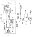
- Fig. 8 shows the detials of the relation between the controller unit 100 and a scanner unit 340 in Fig. 7.
- the parts and components similar to those in Fig. 7 are designated by the same reference numerals and their detailed descriptions are omitted.
- reference numeral 340 denotes the scanner unit having a scanner driver and control unit 341.
- the scanner clock divider 102 of the controller unit 100 frequency divides a reference signal from the oscillator 104 comprising a crystal oscillator in accordance with a divider ratio selection signal from the main control unit 101, thereby forming a scan clock signal and outputting to the scanner unit 340.
- the divider ratio selection signal is constructed by two bits and total four kinds of rotational speed changeover signals can be output.
- the rotational speeds which can be switched are not limited to the above example. It will be obviously understood that a further larger number of bits are assigned to the divider ratio selection signal, thereby enabling an arbitrary kind of rotational speed to be selected and making it possible to record and output at a number of kinds of resolutions.
- the scanner motor 314 is rotated at a rotational speed corresponding to a scanner clock signal from the scanner clock divider 102.
- the scanner clock signal is compared with a tack signal which is produced due to the rotation of the scanner motor 314 as a reference signal of a phase locked loop (PLL) for the scanner clock signal.
- PLL phase locked loop
- the rotation of the scanner motor 314 is controlled so that both of the scanner clock signal and the tack signal always coincide.
- the constant speed control of the scanner motor 314 corresponding to a desired resolution can be executed.
- the resolution (recording density) can be arbitrarily set.
- the resolution changeover such as 240 dpi ⁇ 300 dpi, 300 dpi ⁇ 400 dpi, or the like can be executed by the same apparatus.
- the main control unit 101 outputs a corresponding resolution changeover signal according to the set input to the scanner clock divider 102. Due to this, the scanner clock divider 102 changes the scanner clock signal and the rotational speed of the scanner motor 314 is changed. In addition to it, a scanner ready signal indicating that the scanner motor 314 is rotating at a predetermined constant rotational speed is set to be false (not ready). Further, at this time, the laser output is inhibited and the rotational speed of the scanner motor 314 is also being changed, so that no BD signal is detected and the BD not-ready state is set.
- the whole LBP apparatus of the embodiment is set into the not-ready state and the printer ready signal is set to be false.
- an input video signal from the external control unit or the like is masked by an AND circuit (not shown) in the BD counter 103 and a laser diode enable signal is produced.
- a development/transfer output is set to the off state.
- the developing/transfer system of the embodiment uses an image forming process by the roller charging/transfer operation. Particularly, a voltage within range about from - hundreds of V to -1 kV is applied as a transfer output in order to clean the transfer roller. Therefore, even if the development/transfer output is in the off state, the toner deposited onto the transfer roller can be transferred onto the photo sensitive drum 331.
- the scanner driver control unit 341 changes the rotational speed of the scanner motor 314 in corres pondence to the scanner clock signal, thereby controlling the rotational speed to a predetermined rotational speed which is specified by the resolution changeover signal (divider ratio selection signal).
- a scanner ready signal is set to "1" (ready).
- the main control unit 101 Upon reception of the scanner ready signal of the "1" level, the main control unit 101 executes the following control to the transfer output at least after the development output was turned off (after the off state was confirmed).
- a predetermined positive side bias voltage smaller than an ordinary transfer output is applied.
- this method is effective means to erase a trace of the recording medium and is used to equalize impedances between the photo sensitive drum 331 and the transfer roller 332 in the cases where the recording medium exists and where it does not exist.
- a bias voltage V t0 is determined by a mechanism and a construction of the LBP. In the apparatus, V t0 is set to about 2 kV which is equal to the half voltage of the ordinary transfer output.
- V t0 is not limited to the above value but depends on the environmental conditions, particularly, the humidity or characteristics of the recording medium. It is desirable to set the optimum voltage value by using those condition values as parameters.
- the voltage value can be also automatically adjusted in a manner similar to that mentioned above.
- the laser diode enable output is made active.
- the amplifier 105 is energized and the laser is turned on.
- the laser beam is led to the BD detector through an optical fiber by the BD mirror 320.
- the waveform of the laser beam is shaped by the wave shaper 107.
- the laser beam is sent to the BD counter 103 and the BD signal is detected.
- the exposure is executed until the pulses of the number corresponding to at least two lines (two main scanning operations) are counted in order to discriminate whether the BD period is correct or not.
- the laser beam is irradiated onto the photo sensitive drum 331 (into the image area).
- the sequence to clean the transfer output is further executed, thereby making it difficult to transfer the toner to the transfer roller.
- t denotes a time when the BD sync signal becomes effective after the laser beam was irradiated onto the drum 331 and a time corresponding to at least one or more rotations of the transfer roller 332 after the latent image formed within the above time has passed through a transfer contact with the transfer roller 332.
- Fig. 10 shows the relations among the time when the BD sync signal became effective after the laser beam had been irradiated to the photo sensitive drum 331 in the cleaning sequence of the transfer output and the respective sections at the time t until the transfer roller 332 rotates at least one or more number of times after the latent image produced within the above time passed through the transfer contact with the transfer roller 332.
- V indicates a peripheral velocity of the photo sensitive drum 331 (or transfer roller 332).
- the printer ready signal is set to "1", thereby setting the printer to the ready state.
- the ordinary print sequence is again started by a print signal from the outside.
- Fig. 11 shows a constructional diagram of an LBP in another image forming apparatus in which the developing/transfer system was realized by the electrophotographic process by the charging by the charger construction.
- a cartridge 350 shown in Fig. 11 is a unit which can be integratedly exchanged.
- reference numeral 351 denotes a blade; 352 indicates a primary charger; 353 a pre-exposing lamp; and 354 a cleaner blade.
- the cartridge unit 350 also has the photo sensitive drum 331 and the developing cylinder 334.
- a transfer charger 356 and a deelectrifying needle 357 are also arranged below the photo sensitive drum 331 of the cartridge 350.
- An electrostatic latent image formed on the drum 331 is copy transferred onto a recording paper which was conveyed by being synchronized by resist rollers 363.
- reference numeral 361 denotes a lower stage paper feed roller and 362 indicates an upper stage paper feed roller.
- the rollers 361 and 362 are used to feed the recording papers set in a lower or upper stage cassette (not shown) one by one.
- Reference numeral 363 indicates the resist rollers to adjust the conveying timing of the recording paper which was fed;
- 371 indicates a conveying guide portion to convey the recording paper on which the electrostatic latent image was transferred to a position between an upper fixing roller 372 and a lower fixing roller 373; and 374 represents a cleaner of a fixing device.
- the printer can be immediately made ready at the time of the BD ready after completion of the conversion of the rotational speed of the scanner motor 314.
- the printer ready signal can be soon set to "1".
- the transfer output is also set to the off state. Even in this case, for the purpose of a countermeasure for the remaining paper trace, it is also possible to apply the transfer output of V t1 to the transfer charger 356 so as to be equalized with the impedance at the time when the recording paper exists in the portion of the transfer charger 356.
- the transfer output V t1 can be also considered as a sum of energies.
- the voltage V t1 can be also pulse width modulated and output.
- Fig. 12 shows a cleaning timing of the portion of the transfer charger 356 and subsequent control timings.
- Fig. 13 is a block diagram showing an electrical construction of a laser printer 94 including a printer engine unit 95 as a printing apparatus.
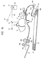
- Fig. 14 is a cross sectional view simply showing a construction regarding the printing operation of the laser printer 94. Explanation will now be made hereinbelow with reference to Figs. 13 and 14.
- the laser printer 94 has, for instance, a video controller unit 96.
- the print data which is output from an external computer or the like is converted into an image signal by the video controller unit 96.
- Reference numeral 51 denotes a laser element such as a laser diode or the like.
- the laser element 51 is turned on and off on the basis of an image signal VDO which is given from the video controller unit 96 to the laser driver 41 through a line 82.
- the video controller unit 96 switches an output speed of the image signal VDO and outputs on the basis of the set resolution.
- various command signals including the designation of the resolution, change thereof, and the like are input from the video controller unit 96 to a microprocessor (hereinafter, referred to as an "MPU") 40 as control means through a line 83 and an interface circuit 93.
- MPU microprocessor
- internal status information in the printer engine unit 95, an error message which will be explained hereinlater, and the like are output to the video controller unit 96 via an interface circuit 87 and a line 88.
- a laser beam from the laser element 51 passes through a collimating lens and a cylindrical lens (not shown) and is reflected to a rotary polygon mirror 52.
- a scanner driver 43 controls a scanner motor 53 on the basis of a signal from the MPU 40, so that the rotary polygon mirror 52 is rotated at a rotational speed corresponding to the set resolution.
- a laser beam 80 which was reflected by the mirror 52 is reflected by a reflecting mirror 54 and scans on a photo sensitive drum 71.
- a BD singal processing circuit 45 outputs a BD signal to specify a writing timing of an image in the main scanning direction to the MPU 40 on the basis of a detection signal from a laser photo detector 55 arranged at the scan start position of the laser beam 80.
- the photo sensitive drum 71 is driven at a predetermined rotational speed by a drum motor 56 and a drum driver 46 irrespective of the set resolution.
- the surface of the drum 71 has uniformly been charged by a corona discharge of a primary charger 73. Therefore, an electrostatic latent image is formed by scanning and exposing the drum 71 by the laser beam 80.
- the electrostatic latent image is developed to a toner image by a developing unit 74 and is copy transferred onto a recording paper 61 as will be explained hereinlater.
- Reference numeral 72 denotes a cleaner to clean the photo sensitive drum 71.
- Reference numeral 62 denotes a cassette to enclose the recording papers 61.
- a plurality of kinds of cassettes 62 are prepared in accordance with the sizes of recording papers 61 to be enclosed.
- One or a plurality of projection portions 62a are formed at a predetermined position(s) in the direction perpendicular to the paper surface in the right edge portion of Fig. 14 of the cassette 62 in accordance with the size of recording paper 61 to be enclosed.
- the projecting portions 62a selectively push a plurality of micro switches 78 provided for the laser printer 94. Due to this, the laser printer 94 recognizes the sizes of recording papers 61. That is, detecting means for detecting the sizes of recording papers 61 is constructed by including the projecting portions 62a and micro switches 78.
- Reference numeral 63 denotes a paper feed cam to feed the recording papers 61 enclosed in the arbitrary one of the cassettes 62 one by one.
- the recording paper 61 is conveyed to the position of paper feed rollers 64a and 64b by the paper feed cam 63.
- Reference numeral 65 denotes a resist shutter to stop the recording paper 61 which is conveyed by the rotations of the rollers 64a and 64b. At this time, the paper feed rollers 64a and 64b continue the rotations while slipping for the recording paper 61.
- a resist solenoid 66 is driven synchronously with the timing of the image formation onto the photo sensitive drum 71 and the resist shutter 65 is released upward in Fig. 2, the recording paper 61 is conveyed to the drum 71 by the paper feed rollers 64a and 64b and conveying rollers 67a and 67b.
- Reference numeral 75 denotes a transfer charger which is driven by a high voltage driver 85 on the basis of a signal from the MPU 40 and the toner image on the drum 71 is transferred onto the recording paper 61 as mentioned above.
- Reference numerals 68a and 68b denote fixing rollers to thermally fix a toner image on the recording paper 61.
- Reference numeral 84 denotes a heater to raise the temperature of the surface of the fixing roller 68a to a predetermined temperature.
- the recording paper 61 printed as mentioned above is delivered onto a stacker 70 by delivery rollers 69a and 69b.
- step T10 in Fig. 15 is first executed and the initialization processings such as to initialize the content of a random access memory provided in the MPU 40 and the like and to rotate the rotary polygon mirror 52 and the like are executed. At this time, the size of recording paper 61 is recognized by the signals from the micro switches 78.
- step T20 a communication processing of a printer control command and the like are executed with the video controller unit 96. That is, as will be explained hereinlater, a command communication control routine is executed and when a command is received, interpretation and return processings of the command or a processing corresponding to the command received is executed.
- the main routine in step T30 the well-known control of the printer and the like are executed.
- step T21 a check is made to see if a printer control command has been sent from the video controller unit 96 or not. If NO, the processing routine is returned.
- step T22 a check is made in step T22 to see if the received command is a resolution changeover request command or not. If a command other than the resolution changeover request command has been received, in step T23, the MPU 40 interprets various kinds of received commands and executes processings corresponding to the commands such as to drive a group of various devices such as primary charger 73 laser element 51, and the like through device drivers and the like.
- the drum motor 56 is driven through the drum driver 46 and the primary charger 73 is also made operative.
- step T22 if a print density changeover request command has been received in step T22, a check is made in step T24 to see if the transfer charger 75 has been turned on or not. If YES, step T28 follows and error information is transmitted from the printer engine unit 95 to the video controller unit 96. The error information is output as one of status information for, e.g., the resolution changeover request command. Due to this, the video controller unit 96 can recognize the fact that the switching of the print density in the printer engine unit 95 was not executed.
- the video controller unit 96 Upon reception of the error information, the video controller unit 96 informs the fact to an external computer or the like or again transmits the resolution changeover request command, for instance, after the transfer charger 75 was turned off, thereby switching the resolution for the next and subsequent pages. Or, even in the case of continuously printing a plurality of pages, the printing operation of the next and subsequent pages is temporarily stopped and a proper processing can be performed.
- the above proper processing is executed on the basis of a software provided in the external apparatus such as a computer or the like.
- step T25 follows and a signal indicative of the resolution from the video controller unit 96 is received.
- the content is updated to the received setting value.
- step T26 a signal is output to the scanner driver 43 and the polygon mirror 52 is rotated at a rotational speed corresponding to the set resolution.
- the resolution in the sub scanning direction is changed.
- the frequency F B of the video clocks of the image signal indicative of the resolution in the main scanning direction is determined by the video controller unit 96 so as to satisfy the above equations.
- step T27 in association with the change of the rotational speed of the polygon mirror 52, to change the output timing of the BD singal, data corresponding to the resolution is given to the BD signal processing circuit 45.
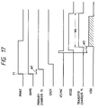
- Fig. 17 is a timing chart for explaining the operation timings in the printing operation.
- the MPU 40 receives it and sets a signal DRMD to a high level and makes the scanner motor 53 and drum motor 56 operative.
- the primary charger 73 is turned on.
- a signal SRDY is set to the high level.
- the printer engine unit 95 Upon completion of the print ready state, the printer engine unit 95 generates a VSYNC request signal. After the elapse of a predetermined time W 2 after the vertical sync signal VSYNC had been output from the video controller unit 96, an image signal VDO is output.
- the resist shutter 65 is released and the transfer charger 75 is activated and the like.
- a release period of the resist shutter 65, an ON period W 4 of the transfer charger 75, and the like are set in correspondence to the size of the recording paper 61 which was detected as mentioned above.
- the MPU 40 outputs the error information without switching the resolution in response to the resolution changeover request command in the ON period W 4 of the transfer charger 75. Since the on/off control of the transfer charger 75 is executed by the MPU 40, the MPU 40 recognizes the on/off state of the transfer charger 75. Therefore, the above operation can be realized by merely changing the software without needing to add a new construction. Moreover, since the period W 4 corresponds to the size of recording paper 61, the ineffective period can be set to a proper length and is not set to a long time in vain.
- the Figure 13 apparatus has been described with respect to the case where the period when the error information is output without performing the resolution changeover operation in response to the resolution changeover request command has been set to the period W 4 when the transfer charger 75 is in the on state.
- the period to output the error information can be also set to, for instance, a period when the video signal of one page is being input or an on period of the primary charger 73 if it is a period corresponding to the size of recording paper 61.
- the above period can be also set to other period such as a period corresponding to the length in the conveying direction of the recording paper 61 after the conveyance of the recording paper 61 was restarted after the resist shutter 65 had been released.
- the invention can be also similarly embodied even in the case of a printing apparatus such that a latent image is formed onto a photo sensitive material by using an LED array or a liquid crystal shutter or the like.
Landscapes
- Engineering & Computer Science (AREA)
- Multimedia (AREA)
- Signal Processing (AREA)
- Physics & Mathematics (AREA)
- Optics & Photonics (AREA)
- General Engineering & Computer Science (AREA)
- General Physics & Mathematics (AREA)
- Theoretical Computer Science (AREA)
- Laser Beam Printer (AREA)
- Fax Reproducing Arrangements (AREA)
- Control Or Security For Electrophotography (AREA)
Claims (14)
- Appareil de formation d'image capable de former une image à l'une d'une pluralité de définitions, comprenant:
un moyen (8, 9) pour faire avancer un support d'enregistrement;
un moyen (30) pour recevoir une commande afin de modifier la définition de l'appareil;
un moyen (S7, S11) pour discriminer si un support d'enregistrement avancé a atteint ou non une position prédéterminée;
un moyen (S12) pour transmettre, à une source (2) de signal d'image, un signal de demande pour demander un signal d'image en réponse à la sortie dudit moyen de discrimination; et
un moyen à retard (S10) pour retarder la transmission du signal de demande jusqu'à ce que le traitement de modification de la définition soit terminé, lorsqu'une commande pour modifier la définition est reçue avant que la sortie dudit moyen de discrimination devienne affirmative. - Appareil selon la revendication 1, dans lequel ledit moyen d'avance fait avancer un support d'enregistrement à partir d'un moyen capable d'empiler une pluralité de supports d'enregistrement en réponse à un signal prédéterminé délivré par la source de signal d'image avant ledit signal de demande.
- Appareil selon la revendication 1 ou 2, dans lequel ledit moyen d'avance comporte un moyen d'alignement du support d'enregistrement avancé.
- Appareil selon la revendication 3, dans lequel la source de signal d'image génère un signal d'image synchronisé avec un signal de synchronisation verticale en réponse audit signal de demande et ledit appareil avance le support d'enregistrement aligné dans la position prédéterminée en synchronisme avec le signal de synchronisation verticale.
- Appareil selon l'une quelconque des revendications 1 à 4, dans lequel ledit appareil n'effectue pas le traitement de modification de la définition lorsque la commande de modification de la définition est reçue après que la sortie dudit moyen de discrimination soit devenue affirmative jusqu'à ce que l'enregistrement du support d'enregistrement avancé soit terminé.
- Appareil selon l'une quelconque des revendications 1 à 4, dans lequel ledit appareil ignore la commande de modification de la définition lorsque la commande pour modifier la définition est reçue après que la discrimination dudit moyen de discrimination soit devenue affirmative.
- Appareil selon l'une quelconque des revendications 1 à 6, comprenant en outre:
un cylindre photosensible (1);
une unité (2, 4, 14, 311, 313, 315) de formation d'image latente électrostatique qui forme une image latente électrostatique sur le cylindre photosensible;
une unité (3) de développement qui forme une image de toner en développant l'image latente électrostatique sur le cylindre photosensible; et
une unité (6) de transfert qui transfère l'image de toner formée sur le cylindre photosensible, sur le support d'enregistrement avancé. - Appareil selon la revendication 7, dans lequel l'unité de formation d'image latente électrostatique comprend:
un générateur (2, 200) de faisceau lumineux qui génère un faisceau lumineux modulé par le signal d'image en provenance de la source de signal d'image; et
un miroir polygonal rotatif (4, 313) pour balayer le faisceau lumineux depuis le générateur de faisceau lumineux sur le cylindre, et
dans lequel la définition est modifiée en modifiant la vitesse de rotation du miroir et la vitesse à laquelle le faisceau lumineux est modulé. - Appareil selon la revendication 8, comprenant en outre un élément (320) de détection de faisceau lumineux qui détecte le faisceau lumineux lorsqu'il est balayé par le miroir dans une région de formation d'image non latente afin de générer un signal de synchronisation horizontale,
dans lequel, lorsque la définition est modifiée, la lumière en provenance du générateur de faisceau lumineux est balayée sur une région comportant une région du cylindre de formation d'image latente, de telle sorte que le faisceau lumineux peut être détecté par l'élément de détection de faisceau lumineux. - Appareil selon la revendication 9, dans lequel la lumière en provenance du générateur de faisceau lumineux est balayée sur la région de formation d'image non latente après que le faisceau lumineux a été détecté par l'élément de détection de faisceau lumineux.
- Appareil selon la revendication 10, dans lequel l'unité de transfert est chargée à un potentiel opposé au potentiel qui est établi lors de l'opération de transfert au cours de la période où le faisceau lumineux est en service.
- Appareil selon l'une quelconque des revendications 7 à 11, dans lequel, lorsque la commande de modification de la définition est reçue après que la sortie dudit moyen de discrimination devient affirmative, ledit appareil n'effectue pas le traitement de modification de la définition tant que les unités de développement et de transfert ne sont pas hors service.
- Appareil de formation d'image selon l'une quelconque des revendications 7 à 12, dans lequel l'unité de transfert comporte un rouleau de transfert.
- Appareil de formation d'image selon l'une quelconque des revendications 7 à 13, dans lequel au moins le cylindre photosensible et l'unité de développement sont logés dans une cartouche.
Applications Claiming Priority (8)
| Application Number | Priority Date | Filing Date | Title |
|---|---|---|---|
| JP23366189A JPH0396382A (ja) | 1989-09-07 | 1989-09-07 | 印字装置 |
| JP233661/89 | 1989-09-07 | ||
| JP23631289A JPH0398382A (ja) | 1989-09-11 | 1989-09-11 | 印字装置 |
| JP236312/89 | 1989-09-11 | ||
| JP1277257A JPH03140263A (ja) | 1989-10-26 | 1989-10-26 | 画像記録装置 |
| JP277257/89 | 1989-10-26 | ||
| JP17882/90 | 1990-01-30 | ||
| JP2017882A JPH03223775A (ja) | 1990-01-30 | 1990-01-30 | 画像形成装置 |
Publications (3)
| Publication Number | Publication Date |
|---|---|
| EP0416832A2 EP0416832A2 (fr) | 1991-03-13 |
| EP0416832A3 EP0416832A3 (en) | 1992-12-16 |
| EP0416832B1 true EP0416832B1 (fr) | 1996-07-10 |
Family
ID=27456850
Family Applications (1)
| Application Number | Title | Priority Date | Filing Date |
|---|---|---|---|
| EP90309596A Expired - Lifetime EP0416832B1 (fr) | 1989-09-07 | 1990-09-03 | Dispositif de formation de l'image |
Country Status (3)
| Country | Link |
|---|---|
| US (2) | US5475414A (fr) |
| EP (1) | EP0416832B1 (fr) |
| DE (1) | DE69027723T2 (fr) |
Families Citing this family (15)
| Publication number | Priority date | Publication date | Assignee | Title |
|---|---|---|---|---|
| EP0416886B1 (fr) * | 1989-09-06 | 1995-04-19 | Canon Kabushiki Kaisha | Appareil d'enregistrement d'images |
| US6064419A (en) * | 1994-12-28 | 2000-05-16 | Canon Kabushiki Kaisha | Timings of rotational speed in a laser beam printer |
| JPH11348343A (ja) | 1998-06-03 | 1999-12-21 | Canon Inc | 画像形成方法および装置 |
| JP2000203082A (ja) * | 1999-01-13 | 2000-07-25 | Ricoh Co Ltd | 画像形成装置 |
| JP3821080B2 (ja) * | 2002-09-30 | 2006-09-13 | ブラザー工業株式会社 | 印刷装置 |
| JP2005001136A (ja) * | 2003-06-09 | 2005-01-06 | Noritsu Koki Co Ltd | 露光装置及び露光方法 |
| US8693048B2 (en) * | 2007-01-24 | 2014-04-08 | Xerox Corporation | Sub-pixel generation for high speed color laser printers using a clamping technique for PLL (phase locked loop) circuitry |
| US8488186B2 (en) * | 2007-01-24 | 2013-07-16 | Xerox Corporation | Gradual charge pump technique for optimizing phase locked loop (PLL) function in sub-pixel generation for high speed laser printers switching between different speeds |
| US20090244633A1 (en) * | 2008-03-31 | 2009-10-01 | Konica Minolta Systems Laboratory, Inc. | Systems and Methods for Color Data Compression |
| US8098942B2 (en) * | 2008-06-30 | 2012-01-17 | Konica Minolta Systems Laboratory, Inc. | Systems and methods for color data compression |
| US8068667B2 (en) * | 2008-03-31 | 2011-11-29 | Konica Minolta Systems Laboratory, Inc. | Systems and methods for color data compression |
| US20090244601A1 (en) * | 2008-03-31 | 2009-10-01 | Konica Minolta Systems Laboratory, Inc. | Systems and Methods for Color Data Compression |
| US8155436B2 (en) * | 2008-03-31 | 2012-04-10 | Konica Minolta Laboratory U.S.A., Inc. | Systems and methods for color data compression |
| US8121435B2 (en) * | 2008-03-31 | 2012-02-21 | Konica Minolta Laboratory U.S.A., Inc. | Systems and methods for resolution switching |
| JP5903406B2 (ja) | 2013-06-28 | 2016-04-13 | 京セラドキュメントソリューションズ株式会社 | 光ビームセンサーの位置調整方法 |
Family Cites Families (25)
| Publication number | Priority date | Publication date | Assignee | Title |
|---|---|---|---|---|
| US3854974A (en) * | 1970-08-28 | 1974-12-17 | Xerox Corp | Method for transferring a toner image |
| JPS52105734A (en) * | 1976-03-01 | 1977-09-05 | Canon Inc | Signal coverter |
| US4130841A (en) * | 1977-03-07 | 1978-12-19 | Xerox Corporation | Variable frequency half-tone imaging apparatus |
| US4393387A (en) * | 1979-09-14 | 1983-07-12 | Canon Kabushiki Kaisha | Beam recording apparatus effecting the recording by a plurality of beams |
| US4876562A (en) * | 1984-09-25 | 1989-10-24 | Canon Kabushiki Kaisha | Image recording apparatus |
| US4952948A (en) * | 1984-09-25 | 1990-08-28 | Canon Kabushiki Kaisha | Image recording apparatus |
| JPS61277255A (ja) * | 1985-05-31 | 1986-12-08 | Toshiba Corp | レ−ザプリンタ |
| JPS6242166A (ja) * | 1985-08-20 | 1987-02-24 | Canon Inc | 画像記録装置 |
| US4862288A (en) * | 1986-10-27 | 1989-08-29 | Minolta Camera Kabushiki Kaisha | Printing apparatus with plural density control |
| JPS63124786A (ja) * | 1986-11-14 | 1988-05-28 | Canon Inc | モ−タ制御装置 |
| US4847643A (en) * | 1987-02-19 | 1989-07-11 | Minolta Camera Kabushiki Kaisha | Laser printing system |
| US4872025A (en) * | 1987-03-30 | 1989-10-03 | Minolta Camera Kabushiki Kaisha | Laser printer capable of changing a pixel density |
| JP2715411B2 (ja) * | 1987-05-19 | 1998-02-18 | ミノルタ株式会社 | レーザプリンタ |
| JPS6446724A (en) * | 1987-08-17 | 1989-02-21 | Canon Kk | Image recorder |
| GB8811568D0 (en) * | 1988-05-16 | 1988-06-22 | Crosfield Electronics Ltd | Producing half-tone images |
| JPH0239171A (ja) * | 1988-07-29 | 1990-02-08 | Hitachi Koki Co Ltd | 電子写真式印刷装置 |
| US5361329A (en) * | 1988-08-11 | 1994-11-01 | Canon Kabushiki Kaisha | Data processing apparatus |
| KR910009142B1 (ko) * | 1988-08-12 | 1991-10-31 | 가부시기가이샤 히다찌세이사꾸쇼 | 복수 광빔의 주사빔 주사간격을 가변으로 하는 제어수단을 구비한 광빔주사장치 |
| EP0649247B1 (fr) * | 1988-09-06 | 2002-12-11 | Canon Kabushiki Kaisha | Appareil de commande d'intensité d'illumination |
| US5140349A (en) * | 1988-09-27 | 1992-08-18 | Canon Kabushiki Kaisha | Recording apparatus |
| US5012293A (en) * | 1989-08-24 | 1991-04-30 | International Business Machines Corporation | Transfer station control in an electrophotographic reproduction device |
| JPH0387773A (ja) * | 1989-08-31 | 1991-04-12 | Canon Inc | 画像印字装置 |
| JPH03110596A (ja) * | 1989-09-26 | 1991-05-10 | Canon Inc | 印刷装置 |
| US5258779A (en) * | 1990-02-17 | 1993-11-02 | Canon Kabushiki Kaisha | Image forming apparatus with means for controlling feeding of recording medium |
| US4993772A (en) * | 1990-02-20 | 1991-02-19 | Irvin Automotive Products, Inc. | Spring-loaded, dual-action hinge assembly for vehicle accessories |
-
1990
- 1990-09-03 EP EP90309596A patent/EP0416832B1/fr not_active Expired - Lifetime
- 1990-09-03 DE DE69027723T patent/DE69027723T2/de not_active Expired - Fee Related
- 1990-09-07 US US07/578,443 patent/US5475414A/en not_active Expired - Fee Related
-
1995
- 1995-06-02 US US08/458,259 patent/US5610646A/en not_active Expired - Fee Related
Also Published As
| Publication number | Publication date |
|---|---|
| US5610646A (en) | 1997-03-11 |
| DE69027723D1 (de) | 1996-08-14 |
| EP0416832A3 (en) | 1992-12-16 |
| DE69027723T2 (de) | 1997-01-09 |
| US5475414A (en) | 1995-12-12 |
| EP0416832A2 (fr) | 1991-03-13 |
Similar Documents
| Publication | Publication Date | Title |
|---|---|---|
| US5475414A (en) | Image forming apparatus having plural printing resolutions | |
| US4712118A (en) | Laser beam printer | |
| US5742327A (en) | Recording apparatus | |
| US5374947A (en) | Laser beam printer capable of changing scanning density and paper transport speed | |
| US5386223A (en) | Method of apparatus for recording color image by overlapping toner images of different colors | |
| US4814792A (en) | Lateral registration adjusting device for use in a laser beam printer | |
| US5512929A (en) | Image forming apparatus with fixer temperature control | |
| US5285247A (en) | Linear print head image forming apparatus with magnification adjustment | |
| US7129966B2 (en) | Multi-beam image forming apparatus with overlapped scanning | |
| US5408304A (en) | Image forming apparatus having a pre-paper-feed function | |
| US4972209A (en) | Image recording forming blanks in peripheral edges | |
| JPH04329512A (ja) | 画像記録装置 | |
| US5285221A (en) | Color image electrophotographic apparatus having photosensitive body and intermediate transfer body | |
| EP0624025B1 (fr) | Dispositif de génération d'images | |
| US6363227B1 (en) | Image forming apparatus and control method for image forming apparatus which detects a status change with respect to an abnormality in the apparatus | |
| JP2006015566A (ja) | 画像形成装置 | |
| JP2875411B2 (ja) | プリンタ装置 | |
| JPH1067137A (ja) | 画像形成装置 | |
| JP4235292B2 (ja) | 画像形成装置 | |
| JPH0398382A (ja) | 印字装置 | |
| US20030202084A1 (en) | Image forming apparatus and method of controlling light beam | |
| JP2938142B2 (ja) | レーザ記録装置 | |
| JPH0462078A (ja) | 画像形成装置 | |
| JPH04247760A (ja) | 画像形成装置 | |
| JPH03114862A (ja) | 印字装置 |
Legal Events
| Date | Code | Title | Description |
|---|---|---|---|
| PUAI | Public reference made under article 153(3) epc to a published international application that has entered the european phase |
Free format text: ORIGINAL CODE: 0009012 |
|
| 17P | Request for examination filed |
Effective date: 19901231 |
|
| AK | Designated contracting states |
Kind code of ref document: A2 Designated state(s): DE FR GB IT |
|
| PUAL | Search report despatched |
Free format text: ORIGINAL CODE: 0009013 |
|
| AK | Designated contracting states |
Kind code of ref document: A3 Designated state(s): DE FR GB IT |
|
| RHK1 | Main classification (correction) |
Ipc: B41J 2/44 |
|
| 17Q | First examination report despatched |
Effective date: 19940406 |
|
| GRAH | Despatch of communication of intention to grant a patent |
Free format text: ORIGINAL CODE: EPIDOS IGRA |
|
| GRAH | Despatch of communication of intention to grant a patent |
Free format text: ORIGINAL CODE: EPIDOS IGRA |
|
| GRAA | (expected) grant |
Free format text: ORIGINAL CODE: 0009210 |
|
| ITF | It: translation for a ep patent filed | ||
| AK | Designated contracting states |
Kind code of ref document: B1 Designated state(s): DE FR GB IT |
|
| REF | Corresponds to: |
Ref document number: 69027723 Country of ref document: DE Date of ref document: 19960814 |
|
| ET | Fr: translation filed | ||
| PLBE | No opposition filed within time limit |
Free format text: ORIGINAL CODE: 0009261 |
|
| STAA | Information on the status of an ep patent application or granted ep patent |
Free format text: STATUS: NO OPPOSITION FILED WITHIN TIME LIMIT |
|
| 26N | No opposition filed | ||
| REG | Reference to a national code |
Ref country code: GB Ref legal event code: IF02 |
|
| PGFP | Annual fee paid to national office [announced via postgrant information from national office to epo] |
Ref country code: GB Payment date: 20030820 Year of fee payment: 14 |
|
| PGFP | Annual fee paid to national office [announced via postgrant information from national office to epo] |
Ref country code: FR Payment date: 20030919 Year of fee payment: 14 Ref country code: DE Payment date: 20030919 Year of fee payment: 14 |
|
| PG25 | Lapsed in a contracting state [announced via postgrant information from national office to epo] |
Ref country code: GB Free format text: LAPSE BECAUSE OF NON-PAYMENT OF DUE FEES Effective date: 20040903 |
|
| PG25 | Lapsed in a contracting state [announced via postgrant information from national office to epo] |
Ref country code: DE Free format text: LAPSE BECAUSE OF NON-PAYMENT OF DUE FEES Effective date: 20050401 |
|
| GBPC | Gb: european patent ceased through non-payment of renewal fee |
Effective date: 20040903 |
|
| PG25 | Lapsed in a contracting state [announced via postgrant information from national office to epo] |
Ref country code: FR Free format text: LAPSE BECAUSE OF NON-PAYMENT OF DUE FEES Effective date: 20050531 |
|
| REG | Reference to a national code |
Ref country code: FR Ref legal event code: ST |
|
| PG25 | Lapsed in a contracting state [announced via postgrant information from national office to epo] |
Ref country code: IT Free format text: LAPSE BECAUSE OF NON-PAYMENT OF DUE FEES;WARNING: LAPSES OF ITALIAN PATENTS WITH EFFECTIVE DATE BEFORE 2007 MAY HAVE OCCURRED AT ANY TIME BEFORE 2007. THE CORRECT EFFECTIVE DATE MAY BE DIFFERENT FROM THE ONE RECORDED. Effective date: 20050903 |