EP0416880A2 - Walzwerk und Walzverfahren - Google Patents
Walzwerk und Walzverfahren Download PDFInfo
- Publication number
- EP0416880A2 EP0416880A2 EP90309678A EP90309678A EP0416880A2 EP 0416880 A2 EP0416880 A2 EP 0416880A2 EP 90309678 A EP90309678 A EP 90309678A EP 90309678 A EP90309678 A EP 90309678A EP 0416880 A2 EP0416880 A2 EP 0416880A2
- Authority
- EP
- European Patent Office
- Prior art keywords
- work rolls
- rolling
- support rollers
- rolls
- work
- Prior art date
- Legal status (The legal status is an assumption and is not a legal conclusion. Google has not performed a legal analysis and makes no representation as to the accuracy of the status listed.)
- Granted
Links
Images




Classifications
-
- B—PERFORMING OPERATIONS; TRANSPORTING
- B21—MECHANICAL METAL-WORKING WITHOUT ESSENTIALLY REMOVING MATERIAL; PUNCHING METAL
- B21B—ROLLING OF METAL
- B21B13/00—Metal-rolling stands, i.e. an assembly composed of a stand frame, rolls, and accessories
- B21B13/14—Metal-rolling stands, i.e. an assembly composed of a stand frame, rolls, and accessories having counter-pressure devices acting on rolls to inhibit deflection of same under load; Back-up rolls
-
- B—PERFORMING OPERATIONS; TRANSPORTING
- B21—MECHANICAL METAL-WORKING WITHOUT ESSENTIALLY REMOVING MATERIAL; PUNCHING METAL
- B21B—ROLLING OF METAL
- B21B13/00—Metal-rolling stands, i.e. an assembly composed of a stand frame, rolls, and accessories
- B21B13/14—Metal-rolling stands, i.e. an assembly composed of a stand frame, rolls, and accessories having counter-pressure devices acting on rolls to inhibit deflection of same under load; Back-up rolls
- B21B13/145—Lateral support devices for rolls acting mainly in a direction parallel to the movement of the product
-
- B—PERFORMING OPERATIONS; TRANSPORTING
- B21—MECHANICAL METAL-WORKING WITHOUT ESSENTIALLY REMOVING MATERIAL; PUNCHING METAL
- B21B—ROLLING OF METAL
- B21B29/00—Counter-pressure devices acting on rolls to inhibit deflection of same under load, e.g. backing rolls ; Roll bending devices, e.g. hydraulic actuators acting on roll shaft ends
-
- B—PERFORMING OPERATIONS; TRANSPORTING
- B21—MECHANICAL METAL-WORKING WITHOUT ESSENTIALLY REMOVING MATERIAL; PUNCHING METAL
- B21B—ROLLING OF METAL
- B21B1/00—Metal-rolling methods or mills for making semi-finished products of solid or profiled cross-section; Sequence of operations in milling trains; Layout of rolling-mill plant, e.g. grouping of stands; Succession of passes or of sectional pass alternations
- B21B1/40—Metal-rolling methods or mills for making semi-finished products of solid or profiled cross-section; Sequence of operations in milling trains; Layout of rolling-mill plant, e.g. grouping of stands; Succession of passes or of sectional pass alternations for rolling foils which present special problems, e.g. because of thinness
-
- B—PERFORMING OPERATIONS; TRANSPORTING
- B21—MECHANICAL METAL-WORKING WITHOUT ESSENTIALLY REMOVING MATERIAL; PUNCHING METAL
- B21B—ROLLING OF METAL
- B21B31/00—Rolling stand structures; Mounting, adjusting, or interchanging rolls, roll mountings, or stand frames
- B21B31/16—Adjusting or positioning rolls
- B21B31/20—Adjusting or positioning rolls by moving rolls perpendicularly to roll axis
- B21B2031/206—Horizontal offset of work rolls
Definitions
- the present invention relates to a rolling mill and rolling method, and more particularly to a rolling mill and a rolling method for metal strip, in which relatively small-diameter working rolls suitable for rolling hard, thin material are used.
- a rolling mill for rolling metal strip particularly hard, very thin material such a stainless steel, high carbon steel, spring steel and some alloy steels such as titanium alloy and high nickel alloy steels, uses small-diameter working rolls. Since such working rolls have too small a diameter for application of the rolling torque directly to them, there have been developed multiple-roll rolling mills such as the Sendzimir mill and other mills in which the drive is transmitted to the working rolls via one or more pairs of backup rolls through which drive is transmitted to the working rolls. Methods have also been developed for controlling the bending of the work rolls in such rolling mills, in order to achieve flatness of the product, by relative shifting of the backup rolls in the axial direction and also by applying vertical roll bending forces to the work rolls and the backup rolls.
- the present invention is concerned with control of bending in the horizontal rolling direction, i.e. in the direction of travel of the material being rolled.
- This direction is referred to herein as the "horizontal direction” or “horizontal rolling direction” and these expressions do not include the axial direction of the rolls.
- US-A-4631948 discloses a rolling mill in which drive is transmitted to the work rolls by backup rolls, and the work rolls are offset from the axial plane of the backup rolls in the horizontal direction. It is known that horizontal bending of the work rolls is reduced by offsetting the working roll axial plane from the backup roll axial plane in the direction downstream (in the rolling direction) of the backup roll plane because the frictional force applied by the backup rolls to the work rolls is then in opposition to the horizontal component of the rolling force (i.e. the force applied to the material being rolled by the work rolls).
- the work rolls are maintained in a fixed horizontal position in the mill frame, offset relative to the backup rolls, and are supported in the horizontal direction by rollers which contact the work rolls at portions thereof which are outside the region contacting the roll material but are of the same diameter as that region.
- the support rolls which are on both sides of the work rolls in the horizontal direction, are forced against the work rolls hydraulically and serve to control horizontal bending, by applying bending forces to the rolls horizontally between their fixed bearing blocks. It is stated that the hydraulic cylinders which push the support rollers are independently controlled to produce the desired bending.
- appropriate control of the horizontal forces which vary in dependence not only on the rolling direction but also various other factors during rolling such as torque and rolling force, is not possible.
- JP-A-63-60006 (1988) shows an arrangement closely similar to that of US-A-4361948, in which again the bearing blocks of the work rolls are horizontally fixed.
- JP-A-60-18206 (1985) shows a similar application of rollers to both sides of both ends of both work rolls, to provide horizontal support of the work rolls.
- the rollers which are paired are applied by a mechanical adjustment system against the work rolls. All of the rollers are apparently adjustable in the horizontal direction, but there is no suggestion or control of the horizontal position of the work rolls which are shown with their axes in the vertical plane of the axes of backup rolls.
- the journal bearings of the work rolls may be removed, presumably since all horizontal force is controlled by the rollers. No vertical roll bending is employed. If it is additionally required to apply vertical bending forces for vertical roll bending, it is not possible to remove the journal bearings since the vertical force must be applied through such bearings.
- this prior art disclosure suggests no solutions to the problems of control of vertical or horizontal roll bending.
- JP-A-63-13024 (1988) in contrast describes the horizontal positioning of the work rolls by means of hydraulic cylinders acting on their bearing blocks. While this approach can restrict the amount of horizontal bending, by positioning the rolls appropriately for each rolling operation, it cannot supply any solution to the problem of out-of-plane bending in the horizontal direction arising from the relatively small resistance to bending of the small diameter work rolls.
- Control of bending of the work rolls across the whole width of the work rolls is provided by a system of support rolls, such as in a Sendzimir rolling mill mentioned above.
- a system of support rolls such as in a Sendzimir rolling mill mentioned above.
- US-A-4719784 where a system of two support rolls in succession are carried by arms projecting from a support beam extending across the mill.
- the support beam carries a plurality of axially spaced rolling bearings providing horizontal support of the support rollers.
- the plane of the axes of the work roll, the two support rolls and the bearings is nearly horizontal. While such an arrangement provides good horizontal support of the work roll, it has the problem that the spaced bearings mark the support roll and these marks are transferred to the work roll, leading to transfer marking of the rolled product.
- Another problem is that the support rolls interfere with cooling of the work rolls.
- the object of the invention is to provide control of the horizontal bending of the work rolls and in particular to permit the reduction of work roll diameter by appropriately balancing the forces arising and reducing their effects upon the work rolls.
- Another object is to provide a rolling method which results in good shape of the rolled product by reduction of horizontal bending of the work rolls.
- the strip comes into contact with the work rolls earlier at its central region than at the edge regions, so that the central region becomes thinner than the edge regions. If, on the contrary, the work rolls are concavely bent toward the strip entrance side, the edge regions some into contact with the work rolls earlier so that they become thinner than the central region.
- the present invention makes it possible to overcome the problems discussed above and provides the novel concept of combining firstly shifting the work rolls to a desired offset location relative to the vertical backup roll plane by means of position control of support rollers which engage the work rolls outside the work regions and secondly application of force to control horizontal work roll bending through these support rollers.
- the bearings of the work rolls are horizontally shiftable, preferably being substantially unrestrained in the horizontal rolling direction, even during rolling.
- the invention provides several advantages. Horizontal bending of the work rolls is reduced firstly by their offset location during rolling and secondly by the control force applied by the support rollers.
- the location of the support rollers between the work regions and the bearings preferably at the full barrel diameter of the work rolls, reduces the free span of the work rolls, which also reduces horizontal bending, and avoids marking of the rolled strip by transfer marks from bearings. Additionally good cooling of the work rolls is possible.
- the free horizontal movement of the bearing boxes leads to a simple construction.
- the application of forces to control vertical bending e.g. through the bearings, and the application of forces to control horizontal bending through the support rollers can be independent, permitting excellent and accurate control of the work roll bending.
- the present invention provides a rolling mill for rolling metal strip moving in a horizontal rolling direction, having
- both work rolls are supported by the support rollers on both sides in the horizontal rolling direction.
- the support rollers are preferably displaceable so that the selectable positions of the work rolls include positions of the work roll axes at both sides of the backup roll plane.
- the support rollers at a first side of the work rolls are mounted by mounting means providing position control of the support rollers on that side, and the support rollers at the other side of the work rolls are mounted by means providing control of the force applied by the support rollers on that other side to the work rolls.
- the mounting means preferably provides mechanically adjustable predetermined location of the support rollers and at the other side the mounting means applies an adjustable force hydraulically to the support rollers.
- each intermediate region of the work rolls contacted by the support rollers there are at least two of the support rollers spaced apart in the axial direction of the work roll. These two support rollers are preferably rigidly linked to each other so as together to resist bending of the work roll in the horizontal rolling direction. This increases the effective length of the work roll to which the force controlling horizontal roll bending is applied.
- the rolling mill of the invention preferably has control means for the support rollers adapted and arranged to move all the support rollers preferably in unison in the same direction so as to move the work rolls to a predetermined offset location.
- the invention further provides a method of operating a rolling mill for metal strip wherein the strip moving in a horizontal rolling direction is rolled by a pair of work rolls which are driven and supported vertically by a pair of backup rolls and are supported in the horizontal rolling direction by a plurality of support rollers which engage locations of the work rolls confined to intermediate regions between work regions where the work rolls contact strip being rolled and bearings for the work rolls.
- the method is characterized by displacing the support rollers so as to move the work rolls to a predetermined offset position at which the vertical rolling plane in which their axes lie is offset from the vertical backup roll plane in which the axes of the backup rolls lie, and thereafter maintaining the position of the support rollers so as to maintain the work rolls at the predetermined offset position during a rolling operation.
- the predetermined position is selected so that the bending forces tending to bend the work rolls in the horizontal rolling direction during the rolling operation are less when the work rolls are at the predetermined offset location than when the vertical rolling plane coincides with the vertical backup plane.
- ⁇ 1 (Q/384EI).W2.(12L - 7W) (1).
- ⁇ 1 the deflection of the work rolls at their region contacting the rolled material
- Q the horizontal bending force
- W the width of the material
- L the distance between fulcrums
- E the modulus of elasticity of the work rolls
- I the geometrical moment of inertia of the work rolls.
- the deflection ( ⁇ 2) is expressed in the following: wherein 1 is the distance between the two fulcrums on each side.
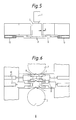
- the warp of the working rolls can be reduced to about one third, as compared with the arrangement of Fig. 4(a), if practical sizes are adopted.
- a first effect of the present invention is to reduce the horizontal bending force, which is achieved by moving the work rolls in the horizontal rolling direction to a position at or closer to the ideal dynamically balanced position where the horizontal force is balanced with respect to the rolling load, the driving tangential force and the difference between the front and back tensions of the strip being rolled.
- a second effect is to improve the rigidity against the deflection of the work rolls with respect to the fluctuating disturbances and errors which cannot be prevented by the first effect.
- the interbearing distance at the two end portions of the rolls is 1.5 times as large as the maximum width of rolled material. If the roll barrel portions are provided with the support rollers, that distance can be effectively reduced to about 1.1 times, and the bending of the working rolls can, according to equation (1) above, be reduced to about one half, as follows:
- the bending of the work rolls can be reduced about one third in the case of Fig. 4(b), as compared with that of Fig. 4(a).
- the reaction R2 is (R2 + Q/2), which is larger by R3 than that of Fig. 4(a).
- the value R3 becomes substantially equal to Q/2, which is about two times as large as the value R1 of Fig. 4(a).
- Methods D and E above are examples of the present invention and correspond to the cases of Figs. 4(a) and 4(b) respectively.
- the work rolls can have their diameters reduced more than in the prior art while avoiding flaws in the material due to the presence of the horizontal support rollers, supplying rolled products having an excellent surface quality. Since, moreover, a vertical bending for the shape control can additionally be exerted upon the working rolls, the shape of the product can be well controlled. In respect of the horizontal bending disturbances of the work rolls, the horizontal force can be reduced by the offset adjustment. In respect of the errors, the work rolls can be supported highly rigidly only against the horizontal bending so that the disturbances can be prevented to maintain good shape of the rolled products. By the means thus far described, very thin, hard materials can be stably rolled and produced by making use of the small-diameter working rolls.
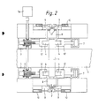
- Figs. 1 and 2 show one embodiment of the rolling mill according to the present invention, which is a representative six-high rolling mill, in which a rolled material 11 is shown passing between a pair of work rolls 1.
- Intermediate backup rolls 2 and outer backup rolls 3 of increasing diameter are disposed above and below the work rolls 1.
- the work rolls 1 have too small a diameter to receive a torque necessary for the rolling operations.
- the torque is transmitted to the intermediate rolls 2 or to the backup rolls 3, and by them to the work rolls.
- the backup rolls 2 and 3 are thus effective to support the work rolls 1 vertically and transmit rotational drive to them, in known manner.
- the work rolls 1 are supported at the entrance and exit sides of the rolled material 11 and at their barrel portions (i.e. regions having the same diameter as the work regions contacted by the material 11) outside the maximum width of the material 1 by support rollers 4.
- These support rollers 4 are individually supported in a rotatable manner by brackets 12.
- These brackets 12 are moved and are supported at one of the entrance and exit sides of the material 11 by mechanical positioning means 5, specifically a worm-screw and rotating nut device driven by a drive motor 5a, and at the other side by hydraulic cylinders 7.
- Load cells 6 detect load applied by the positioning means 5.
- Fig. 1 indicates three positions of the rolls 1 and rollers 4, explained below.
- the work rolls 1 are equipped at their two ends with bearing boxes 8 which accommodate bearings supporting the work rolls 1.
- the bearing boxes 8 have their sides facing in the horizontal direction (rolling direction) arranged with a small gap g from other parts.
- Keeper plates 9 are thus arranged with the small gap g from the bearing boxes 8 and can be moved by cylinders 10.
- the vertical support of the bearing blocks 8 is not shown in the drawings, for the sake of clarity. It is performed in a known manner by providing flat horizontal upper and lower surfaces on the bearing blocks 8, which surfaces can slide horizontally on upper and lower supports. The vertical work roll bending force is applied through these upper and lower supports, but does not prevent horizontal shifting of the bearing blocks 8. Roller bearings 13 transmit axial force to the keeper plates 9, to restrain axial movement, while allowing the horizontal movement of the bearing boxes 8.
- the horizontal bending force applied to the work rolls 1 consists of not only the driving tangential force transmitted from the intermediate backup rolls 2 but also the tensions applied in the direction of movement to the left hand and right hand portions of the rolled material 11.
- an optimum horizontal offset ⁇ 1 or ⁇ 2 according to the direction of movement of the material 1 and the rolling conditions is selected so as to establish a horizontal component of the rolling load which at least partly balances the aforementioned horizontal bending force.
- the offset ⁇ 1 or ⁇ 2 is an offset of the vertical rolling plane defined by the axes of the work rolls 1 relative to the vertical backup roll plane defined by the axes of the intermediate rolls 2.
- the right hand and left hand support rollers 4 have their positions adjusted by the positioning means 5 for over a range of positions on both sides of the state of zero offset. This adjustment is accomplished under the geometrical conditions which are determined by the diameters of the work rolls 1 and the support rollers 4, and may be selected such that the pushing force P B of the hydraulic cylinders 7 acting as a prestressing force and the pushing force P A of the positioning means 5 indicated by load cells 6 are equalized by the right hand hydraulic cylinders 7.
- A P B .
- the force applied by the hydraulic cylinders 7 is chosen so that the work rolls are always located against the support rollers held by the mechanical positioning means 5. In this way the offset position of the work rolls is maintained, and the horizontal rolling forces are accommodated.
- the offset may be decided in most cases to the value which has been preset in advance for each reversal of the direction of rolling.
- Figs. 1 and 2 adopts the concept of Fig. 4(a).
- the bending of the work rolls 1 is larger than that in the case of Fig. 4(b), but the reaction R1 to be applied to the support rolls 4 can be weaker than the reaction R2 so that the entire structure can be simplified, permitting smaller sizes of components.
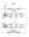
- Fig. 3 shows another embodiment of the present invention.
- the support rollers 3 are arranged further to restrain twisting in the horizontal plane and again act at portions of the work rolls 1 having the barrel diameter outside the material 11.
- this embodiment adopts the concept of Fig. 4(b).
- a plurality of support rollers 4, in this case two, are provided for each bracket 12 and together have a sufficient surface length in the axial direction.
- at least one of the right hand and left hand support rollers 4 is so firmly supported that it may not be twisted by disturbances.
- the two support rollers 2 at each side are thus effectively equivalent to a long rigid roller. It is achieved in this way to support the two ends of the work rolls 1 fixedly. It is recommended that the inner support rollers 4 are thicker so as to have a larger capacity than the outer ones.
- the aforementioned embodiments are suitable for application to a high-speed rolling mill in which the cooling capacity of the work rolls 1 with a roll coolant has to be improved. Coolant may easily be supplied to the roll surface.
- the embodiments provide a structure in which distortion of the working rolls is not likely.
- the positioning means 5 and the hydraulic cylinders 7 may alternatively be simply arranged to move parallel to or at a small angle of inclination to the direction of movement of the rolled material. If, in this case, the work roll diameter is changed, the vertical bending force to be applied to the work rolls by the work roll bender 1 may have to be corrected according to the geometrical conditions.
- the work rolls 1 are equipped at their two ends with the bearing boxes 8 arranged so that the work roll bending (in the vertical direction - not shown here) is adjustably applied to control the shape of the rolled product, in known manner.
- the bearing boxes 8 have at their horizontally facing sides sufficient gaps g so that they will not interfere with the horizontal offset changes.
- the bearing boxes are thus substantially unrestrained in the horizontal rolling direction. As a result, it is possible not only to prevent the hysteresis caused by friction at the sides of the bearing boxes 8 but also to require no offset adjusting means for the bearing boxes 8, thus simplifying the structure.
- the keeper plates 9 are provided.
- the functions required of the keeper plates 9 are a holding function against the movement in the roll axis direction, a function to allow the working rolls 1 to move freely in the horizontal and vertical directions, and a function to prevent the bearing boxes 8 from turning more than is permissible.
- the work rolls 1 have to be prevented from being moved by the axial thrust while being allowed to move freely by the small gaps g between the keeper plates 9 and the sides of the bearing boxes 8.
- the keeper plates can be adjusted in position and also withdrawn completely to allow roll changing, by the cylinder 10. When the keeper plates 9 are shut, they contact at a point F.
- the plates 9 and cylinders 10 should have lengths of stroke corresponding to the desired offset change, in addition to the length of stroke required for retraction of the keeper plates.
- the bearing boxes 8 be not equally between the right hand and left hand sides when the work rolls are to be replaced i.e. not at the symmetrical position. It is, therefore, necessary to bring the bearing boxes 8 to the predetermined operating positions. If the bearing boxes 9 are to be offset rightward, for example, this offset can be accomplished by making the pushing force of the cylinder at the left hand side larger than that at the righthand side and by retracting the hydraulic cylinders. If the bearing boxes are to be offset leftward, on the other hand, this offset can be accomplished by making the pushing force at the righthand side larger than at the lefthand side and by retracting the positioning means 5.
- the keeper plates 9 at the drive side need not be fully opened, and the strokes of the cylinders 10 may be reduced to an amount sufficient to establish a movement corresponding to the offset change during the rolling operation.
- the upper keeper plates 9 can act as stops when the new work rolls 1 are inserted.
- the keeper plates 9 may be disposed only at one upper or lower side, as shown in Figs. 5 and 6, to accomplish both the pushing and retracting actions.
- an axial force is ordinarily established by some error and is supported by the bearing boxes 8 and the keeper plates 9.
- the disturbances resulting from the rolling-directional horizontal forces can be prevented or reduced, but the disturbances resulting from the axial force are not prevented yet.
- the latter disturbances resulting from the axial force can be effectively prevented by interposing directly moving bearings such as roller bearings 13 between the bearing boxes 8 and the keeper plates 9 to allow smooth vertical bending of the working rolls and the vertical movements of the bearing boxes 8 when the thickness of the material 11 is changed.
- the supporting brackets 12 for the support rollers 4 are mounted on the bearing boxes 8 so as to be slidable with the boxes 8 in the horizontal direction, i.e. the direction of movement of the rolled material 1.
- the positioning means 5 and the hydraulic cylinders 7 are mounted on the frame 15 of the mill. At points K, the actuating rods of the positioning means 5 and cylinders 7 make pushing contact with the rear faces of the brackets 12, but are not attached to the brackets 12.
- the support rollers 4 engage the work rolls 1 at their barrel diameter, outside the region contacted by the rolled material 1.
- the keeper plates 9 are withdrawn by cylinders 10 and the bearing boxes 8 with the brackets 12 and rollers 4 are removed with the rolls 1.
- the actuating rods of the positioning means 5 and the cylinders 7 are slightly withdrawn at the contact points K.
- the support rollers 4 can be mounted on the bearing boxes 8 with the correct alignment with respect to the rolls 1. This avoids any generation of vertical force by the horizontal support force applied, when the roll diameter changes. Since the support rollers 4 and brackets 12 are extracted from the mill with the work rolls 1, maintenance of the support rollers 4 is easy. The arrangement allows quick changing of work rolls.
- the rear face of the brackets 12 must be sufficiently large to allow the actuating rods of the positioning means 5 and the cylinders 7 to push effectively, even though the vertical position of the support rollers varies with varying work roll diameter.
- Fig. 10 shows one embodiment of a control system for the rolling method of the present invention.
- control means forming part of the mill controller, are provided to control and coordinate the movements of the support rollers 4, by means of the positioning means 5 and the hydraulic cylinders 7.
- the support rollers 4 are moved in concert, preferably in unison, by this control means, so as to bring the work rolls 1 to the desired offset position.
- the appropriate pressure is maintained in the hydraulic cylinder 7 during rolling, so as to keep the work rolls 1 at the desired offset location.
- the offset position is chosen so that the net horizontal force on the work rolls 1 resulting from the rolling torque, the rolling force and the front and back tensions of the rolled material acts in the same direction during both forward and reverse rolling.
- the hydraulic cylinders 7 can be set to apply a force to the work rolls appropriate to oppose this net force, and thereby maintain the work rolls in a single position, avoiding the need for movement of the rolls between passes of the material.
- Fig. 10 diagrammatically illustrates the control means.
- a programmed data processing unit (DPU) has input data relating to rolling torque T, rolling force P, front tension T f , back tension T f , work roll daimeter D w and backup roll diameter D B for a given rolling operation in the rolling schedule.
- D B is the diameter of the backup roll contacting the work roll.
- T and P depend on the material to be rolled, in accordance with well-known principles.
- Q (F2 + T f ) - (F1 + T b )
- F1 is the frictional force required to drive the work rolls
- F2 is the horizontal component of the rolling force.
- a different value of Q may be chosen at least for reversing rolling.
- the value of ⁇ calculated by the DPU is fed to the mill controller, which causes adjustment of the offset position of the rollers 4 through the positioning means 5 and hydraulic cylinders 7.
Landscapes
- Engineering & Computer Science (AREA)
- Mechanical Engineering (AREA)
- Control Of Metal Rolling (AREA)
- Metal Rolling (AREA)
- Reduction Rolling/Reduction Stand/Operation Of Reduction Machine (AREA)
Applications Claiming Priority (2)
| Application Number | Priority Date | Filing Date | Title |
|---|---|---|---|
| JP231602/89 | 1989-09-08 | ||
| JP23160289 | 1989-09-08 |
Publications (3)
| Publication Number | Publication Date |
|---|---|
| EP0416880A2 true EP0416880A2 (de) | 1991-03-13 |
| EP0416880A3 EP0416880A3 (en) | 1991-04-17 |
| EP0416880B1 EP0416880B1 (de) | 1994-06-01 |
Family
ID=16926086
Family Applications (1)
| Application Number | Title | Priority Date | Filing Date |
|---|---|---|---|
| EP90309678A Expired - Lifetime EP0416880B1 (de) | 1989-09-08 | 1990-09-04 | Walzwerk und Walzverfahren |
Country Status (5)
| Country | Link |
|---|---|
| US (1) | US5119656A (de) |
| EP (1) | EP0416880B1 (de) |
| JP (1) | JP2947901B2 (de) |
| KR (1) | KR930010335B1 (de) |
| DE (1) | DE69009362T2 (de) |
Cited By (7)
| Publication number | Priority date | Publication date | Assignee | Title |
|---|---|---|---|---|
| US5165266A (en) * | 1991-11-04 | 1992-11-24 | International Rolling Mill Consultants, Inc. | Chockless roll support system |
| EP0534602A3 (en) * | 1991-08-26 | 1993-07-28 | Hitachi, Ltd. | Rolling mill and rolling method |
| EP0621087A1 (de) * | 1993-04-22 | 1994-10-26 | Hitachi, Ltd. | Walzwerk und Verfahren |
| US5609054A (en) * | 1991-09-10 | 1997-03-11 | Nippon Steel Corporation | Rolling mill for flat products |
| WO2004052568A1 (de) * | 2002-12-12 | 2004-06-24 | Sms Demag Aktiengesellschaft | Mehrwalzengerüst zum walzen eines metallbandes |
| EP2777833A1 (de) * | 2013-03-13 | 2014-09-17 | Siemens VAI Metals Technologies GmbH | Vorrichtung zur Inbetriebsetzung der Drehbewegung der Arbeitswalzen eines Walzwerks, und Methode zum Auswechseln der genannten Walzen |
| EP2260954B2 (de) † | 2008-03-11 | 2017-11-22 | Nippon Steel & Sumitomo Metal Corporation | Plattenwalzwerk und plattenwalzverfahren |
Families Citing this family (10)
| Publication number | Priority date | Publication date | Assignee | Title |
|---|---|---|---|---|
| US5839313A (en) * | 1998-02-18 | 1998-11-24 | Danieli United, A Division Of Danieli Corporation | Rolling mill with intermediate crossed rolls background |
| DE19944612C1 (de) * | 1999-09-17 | 2000-11-23 | Sundwig Gmbh | Walzgerüst |
| JP5138397B2 (ja) * | 2008-01-25 | 2013-02-06 | 三菱日立製鉄機械株式会社 | 圧延機及びそれを備えたタンデム圧延機 |
| CA2712013C (en) * | 2008-03-04 | 2013-10-08 | Nippon Steel Corporation | Rolling mill and rolling method for flat products of steel |
| CN101780471B (zh) * | 2009-11-12 | 2011-10-05 | 无锡五冶金属压延有限公司 | 冷轧机侧压辊系斜拉装置 |
| DE102009058358A1 (de) | 2009-12-15 | 2011-06-16 | Sms Siemag Ag | Walzgerüst und Verfahren zum Betreiben eines Walzgerüsts |
| JP6809275B2 (ja) * | 2017-02-16 | 2021-01-06 | 日本製鉄株式会社 | 圧延機 |
| EP3381576A1 (de) | 2017-03-31 | 2018-10-03 | Primetals Technologies France SAS | Walzgerüst, das mit einer kontrollvorrichtung für die walzstabilität ausgerüstet ist, und entsprechende methode |
| CN112453343B (zh) * | 2020-11-30 | 2022-02-01 | 中冶赛迪技术研究中心有限公司 | 一种连铸扇形段辊缝在线补偿的方法 |
| AT523437B1 (de) * | 2020-12-09 | 2021-08-15 | Andritz Metals Gemany Gmbh | Walzgeruest |
Family Cites Families (22)
| Publication number | Priority date | Publication date | Assignee | Title |
|---|---|---|---|---|
| US1887870A (en) * | 1929-12-23 | 1932-11-15 | American Brass Co | Rolling mill |
| US4059002A (en) * | 1976-10-20 | 1977-11-22 | Schloemann- Siemag Aktiengesellschaft | Multi-roll rolling mill stand |
| JPS56151111A (en) * | 1980-04-22 | 1981-11-24 | Ishikawajima Harima Heavy Ind Co Ltd | Method and apparatus for controlling sheet camber in differential speed rolling work |
| JPS5791801A (en) * | 1980-11-26 | 1982-06-08 | Nippon Steel Corp | Control method for sectional profile of rolled hoop |
| AT368040B (de) * | 1981-01-14 | 1982-08-25 | Andritz Ag Maschf | Walzenlagerung an walzgeruesten |
| JPS606723B2 (ja) * | 1981-04-08 | 1985-02-20 | 三菱重工業株式会社 | 圧延機のロ−ル軸方向移動装置 |
| JPS59150604A (ja) * | 1983-02-15 | 1984-08-28 | Nippon Kokan Kk <Nkk> | 圧延機 |
| DE3308673A1 (de) * | 1983-03-11 | 1984-09-20 | SMS Schloemann-Siemag AG, 4000 Düsseldorf | Mehrwalzengeruest |
| DE3323641A1 (de) * | 1983-04-02 | 1984-10-04 | SMS Schloemann-Siemag AG, 4000 Düsseldorf | Mehrwalzengeruest |
| JPS59209408A (ja) * | 1983-05-05 | 1984-11-28 | インテグレイテツド インダストリアル システムズ インコ−ポレイテツド | 横方向支え装置 |
| JPS6018206A (ja) * | 1983-07-11 | 1985-01-30 | Nippon Roll Seizo Kk | エツヂサポ−トサイドロ−ルを備えた直列式圧延機 |
| JPS60141311A (ja) * | 1983-12-29 | 1985-07-26 | Hitachi Ltd | 圧延機 |
| KR850007731A (ko) * | 1984-04-02 | 1985-12-09 | 빈센트 지. 지오이아 | 압연기의 압연롤 편향제어방법 |
| DE3431691C2 (de) * | 1984-08-29 | 1987-01-02 | Achenbach Buschhütten GmbH, 5910 Kreuztal | Vorrichtung zur Regelung der Planheit und der Dicke von Walzband in einem Mehrwalzen-Bandwalzgerüst |
| JPS61189809A (ja) * | 1985-02-18 | 1986-08-23 | Ishikawajima Harima Heavy Ind Co Ltd | 圧延装置 |
| JPH0620561B2 (ja) * | 1985-04-03 | 1994-03-23 | 株式会社日立製作所 | 圧延機のロ−ルベンデイング装置 |
| JPS61286010A (ja) * | 1985-06-12 | 1986-12-16 | Hitachi Ltd | 圧延機の板厚制御方法及びその装置 |
| DE3529363A1 (de) * | 1985-08-16 | 1987-02-19 | Schloemann Siemag Ag | Anstellvorrichtung fuer das achsparallele verschieben von walzen eines walzgeruestes |
| US4724698A (en) * | 1985-09-20 | 1988-02-16 | Wean United Rolling Mills, Inc. | Method and apparatus for rolling strip |
| JPS6360006A (ja) * | 1986-08-29 | 1988-03-16 | Kawasaki Heavy Ind Ltd | 圧延スタンド |
| JPS63313024A (ja) * | 1987-06-08 | 1988-12-21 | コルモ−ゲン コ−ポレイシヨン | 遠隔読取型分光測光器 |
| JP2824956B2 (ja) * | 1992-11-06 | 1998-11-18 | 信越化学工業株式会社 | 含フッ素不飽和カルボニル化合物及びその製造方法 |
-
1990
- 1990-09-04 DE DE69009362T patent/DE69009362T2/de not_active Expired - Fee Related
- 1990-09-04 EP EP90309678A patent/EP0416880B1/de not_active Expired - Lifetime
- 1990-09-07 US US07/579,039 patent/US5119656A/en not_active Expired - Lifetime
- 1990-09-07 JP JP23551890A patent/JP2947901B2/ja not_active Expired - Lifetime
- 1990-09-08 KR KR1019900014234A patent/KR930010335B1/ko not_active Expired - Fee Related
Cited By (10)
| Publication number | Priority date | Publication date | Assignee | Title |
|---|---|---|---|---|
| EP0534602A3 (en) * | 1991-08-26 | 1993-07-28 | Hitachi, Ltd. | Rolling mill and rolling method |
| US5406817A (en) * | 1991-08-26 | 1995-04-18 | Hitachi, Ltd. | Rolling mill and rolling method |
| US5609054A (en) * | 1991-09-10 | 1997-03-11 | Nippon Steel Corporation | Rolling mill for flat products |
| US5165266A (en) * | 1991-11-04 | 1992-11-24 | International Rolling Mill Consultants, Inc. | Chockless roll support system |
| EP0621087A1 (de) * | 1993-04-22 | 1994-10-26 | Hitachi, Ltd. | Walzwerk und Verfahren |
| US5560237A (en) * | 1993-04-22 | 1996-10-01 | Yasuda; Kenichi | Rolling mill and method |
| WO2004052568A1 (de) * | 2002-12-12 | 2004-06-24 | Sms Demag Aktiengesellschaft | Mehrwalzengerüst zum walzen eines metallbandes |
| EP2260954B2 (de) † | 2008-03-11 | 2017-11-22 | Nippon Steel & Sumitomo Metal Corporation | Plattenwalzwerk und plattenwalzverfahren |
| EP2777833A1 (de) * | 2013-03-13 | 2014-09-17 | Siemens VAI Metals Technologies GmbH | Vorrichtung zur Inbetriebsetzung der Drehbewegung der Arbeitswalzen eines Walzwerks, und Methode zum Auswechseln der genannten Walzen |
| EP2777832A1 (de) * | 2013-03-13 | 2014-09-17 | Siemens VAI Metals Technologies GmbH | Vorrichtung zur Inbetriebsetzung der Drehbewegung der Arbeitswalzen eines Walzwerks, und Methode zum Auswechseln der genannten Walzen |
Also Published As
| Publication number | Publication date |
|---|---|
| DE69009362D1 (de) | 1994-07-07 |
| EP0416880A3 (en) | 1991-04-17 |
| JPH03174905A (ja) | 1991-07-30 |
| KR910005934A (ko) | 1991-04-27 |
| US5119656A (en) | 1992-06-09 |
| EP0416880B1 (de) | 1994-06-01 |
| KR930010335B1 (ko) | 1993-10-16 |
| DE69009362T2 (de) | 1994-09-08 |
| JP2947901B2 (ja) | 1999-09-13 |
Similar Documents
| Publication | Publication Date | Title |
|---|---|---|
| EP0416880B1 (de) | Walzwerk und Walzverfahren | |
| EP1228818B2 (de) | Walzverfahren für Bandwalzwerk und Bandwalzeinrichtung | |
| JP2733836B2 (ja) | 圧延物、特に圧延板材の製造のための圧延装置 | |
| EP0534602B1 (de) | Walzwerk und Walzverfahren | |
| US5365764A (en) | Cross rolling mill, cross rolling method and cross rolling mill system | |
| AU2009222231B2 (en) | Rolling mill and rolling method for flat products of steel | |
| US5680785A (en) | Metal strip planishing installation | |
| JPS63230208A (ja) | 軸方向に移動可能な圧延ロールを有する圧延機と、この圧延ロールの輪郭形状の調整方法 | |
| JPH0361522B2 (de) | ||
| EP0477751B1 (de) | Walzenbiegemaschine | |
| JPH07164015A (ja) | 軸方向に移動可能なロールを有する圧延機 | |
| US20010020380A1 (en) | Plate rolling mill | |
| CN1004405B (zh) | 多辊轧机 | |
| US3762202A (en) | Rolling mill for flat-rolled products | |
| US6029491A (en) | Continous spiral motion and roll bending system for rolling mills | |
| KR100216299B1 (ko) | 6단 압연기 | |
| US8544308B2 (en) | Roll stand | |
| CA2350534A1 (en) | Rolling stand with back up and working rolls | |
| EP1020237B1 (de) | Walzwerk zum walzen von bändern oder blechen | |
| SU1447447A1 (ru) | Устройство дл регулировани прогиба прокатного валка многовалкового стана | |
| JPH01180708A (ja) | 多段圧延機 | |
| JP2740659B2 (ja) | 形状制御圧延機 | |
| US20240408659A1 (en) | Rolling mill and rolling method | |
| JPS61186112A (ja) | 圧延スタンド | |
| JPS61180602A (ja) | 圧延スタンド |
Legal Events
| Date | Code | Title | Description |
|---|---|---|---|
| PUAI | Public reference made under article 153(3) epc to a published international application that has entered the european phase |
Free format text: ORIGINAL CODE: 0009012 |
|
| PUAL | Search report despatched |
Free format text: ORIGINAL CODE: 0009013 |
|
| 17P | Request for examination filed |
Effective date: 19901020 |
|
| AK | Designated contracting states |
Kind code of ref document: A2 Designated state(s): DE IT |
|
| AK | Designated contracting states |
Kind code of ref document: A3 Designated state(s): DE IT |
|
| 17Q | First examination report despatched |
Effective date: 19920813 |
|
| GRAA | (expected) grant |
Free format text: ORIGINAL CODE: 0009210 |
|
| AK | Designated contracting states |
Kind code of ref document: B1 Designated state(s): DE IT |
|
| REF | Corresponds to: |
Ref document number: 69009362 Country of ref document: DE Date of ref document: 19940707 |
|
| ITF | It: translation for a ep patent filed | ||
| PLBI | Opposition filed |
Free format text: ORIGINAL CODE: 0009260 |
|
| 26 | Opposition filed |
Opponent name: SMS SCHLOEMANN-SIEMAG AG Effective date: 19950301 |
|
| PLBO | Opposition rejected |
Free format text: ORIGINAL CODE: EPIDOS REJO |
|
| PLBN | Opposition rejected |
Free format text: ORIGINAL CODE: 0009273 |
|
| STAA | Information on the status of an ep patent application or granted ep patent |
Free format text: STATUS: OPPOSITION REJECTED |
|
| 27O | Opposition rejected |
Effective date: 19990630 |
|
| PGFP | Annual fee paid to national office [announced via postgrant information from national office to epo] |
Ref country code: IT Payment date: 20080716 Year of fee payment: 19 |
|
| PGFP | Annual fee paid to national office [announced via postgrant information from national office to epo] |
Ref country code: DE Payment date: 20080908 Year of fee payment: 19 |
|
| PG25 | Lapsed in a contracting state [announced via postgrant information from national office to epo] |
Ref country code: DE Free format text: LAPSE BECAUSE OF NON-PAYMENT OF DUE FEES Effective date: 20100401 |
|
| PG25 | Lapsed in a contracting state [announced via postgrant information from national office to epo] |
Ref country code: IT Free format text: LAPSE BECAUSE OF NON-PAYMENT OF DUE FEES Effective date: 20090904 |