EP0417643A2 - Dispositif de production de faisceaux d'électrons, en particulier pour canon à électrons - Google Patents
Dispositif de production de faisceaux d'électrons, en particulier pour canon à électrons Download PDFInfo
- Publication number
- EP0417643A2 EP0417643A2 EP90117161A EP90117161A EP0417643A2 EP 0417643 A2 EP0417643 A2 EP 0417643A2 EP 90117161 A EP90117161 A EP 90117161A EP 90117161 A EP90117161 A EP 90117161A EP 0417643 A2 EP0417643 A2 EP 0417643A2
- Authority
- EP
- European Patent Office
- Prior art keywords
- electron beam
- beam generator
- heat sink
- insulator
- cooling
- Prior art date
- Legal status (The legal status is an assumption and is not a legal conclusion. Google has not performed a legal analysis and makes no representation as to the accuracy of the status listed.)
- Granted
Links
Images

Classifications
-
- H—ELECTRICITY
- H01—ELECTRIC ELEMENTS
- H01J—ELECTRIC DISCHARGE TUBES OR DISCHARGE LAMPS
- H01J37/00—Discharge tubes with provision for introducing objects or material to be exposed to the discharge, e.g. for the purpose of examination or processing thereof
- H01J37/02—Details
- H01J37/04—Arrangements of electrodes and associated parts for generating or controlling the discharge, e.g. electron-optical arrangement or ion-optical arrangement
- H01J37/06—Electron sources; Electron guns
- H01J37/07—Eliminating deleterious effects due to thermal effects or electric or magnetic fields
Definitions
- the invention relates to an electron beam generator, in particular for an electron beam gun, with a high-voltage insulator arranged in a housing and carrying a hot cathode and a control electrode, which can be connected to a high-voltage connection.
- An electron beam generator of the type specified is known from DE-OS 33 33 686.
- the high temperature of the hot cathode leads to strong heating of the adjacent components.
- coolant channels which consist of plastic and are cast into the cast resin compound of the high-voltage insulator, are arranged in the high-voltage insulator to avoid inadmissible heating.
- transformer oil is passed through the coolant channels as a coolant.
- a capsule made of ferromagnetic material in which switching elements for the rectification and sieving of the Wehnelt voltage and the Cathode heating current are housed.
- the invention has for its object to provide an electron gun of the type mentioned, which is characterized by effective cooling even at a low temperature level.
- terminals of the cathode support or in addition also the control electrode are connected to cooling plates inside the high-voltage insulator via connecting lines designed as thermal bridges and that the cooling plates are heat-conducting to a via a thin-walled insulator disk Connect heat sink, which is cooled by a cooling circuit.
- the heat is dissipated from the cathode or the control electrode by components which have a high thermal conductivity due to their material or their geometric shape and are effective even at a low temperature gradient.
- the temperature of the cathode holder and the control electrode at a relatively low level, which is very advantageous for the thermal behavior of the electron gun and for its operational reliability.
- existing components such as the connecting lines, are advantageously used, as a result of which the construction costs are low and the external dimensions of the jet generator can be kept small. While in the connecting lines by the choice of material, eg. B.
- the invention further provides that the cooling plates lie in a common plane and are separated from one another by webs of the high-voltage insulator.
- the two cooling plates of the cathode connections and the cooling plate of the anode connection thus form a uniform, flat contact surface for the insulator disk and the heat sink above it.
- the cooling plates can be connected to contacts through openings in the insulator disk and in Reach through the heat sink and connect the hot cathode or the control electrode to the high-voltage supply.
- the cooling plates thus simultaneously form a section of the electrical connection, and because of their spatial extension they allow the designer space for positioning the contacts leading to the high-voltage supply.
- the insulator disk can consist of a plastic or a ceramic material.
- the production of the insulator disk from the material known under the trade name "Kaptan" has proven to be particularly advantageous.
- the heat sink can advantageously consist of a pot, the flat bottom of which rests on the insulator disk and the heat absorbed is released via its side wall to a heat exchanger of the cooling circuit.
- the heat sink itself is also characterized by a high thermal conductivity and is preferably made of copper or a copper alloy.
- a structural simplification of the electron beam generator can also be achieved according to the invention in that the pot of the heat sink is part of a capsule designed as a Faraday cage, in which circuit elements for controlling the electron beam generator are arranged.
- the heat exchanger encircles the side wall of the heat sink in a ring-shaped manner, the heat exchanger being at ground potential and being separated from the wall of the heat sink by a wall of the high-voltage insulator.
- This configuration has the advantage that water can be used in the cooling circuit.
- the poorer heat conduction of the wall of the high voltage insulator between the heat sink and The heat exchanger is not disadvantageous because, due to the large diameter between the side wall of the heat sink and the heat exchanger, there is a large area for heat transfer.
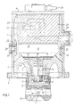
- the electron beam generator shown consists of a cylindrical housing 1, which can be attached in a vacuum-tight manner with an attachment flange 2 to an acceleration chamber, not shown, in which an acceleration anode is located.
- the housing 1 contains a high-voltage insulator 3, which carries a control electrode 6 and a hot cathode 7 on its underside in the center of an annular recess 4 on a fastening flange 5.
- the hot cathode 7 is arranged on a cathode carrier 8, which is mounted in the control electrode 6 with an insulating bearing 9.
- the hot cathode 7 is fastened to two connecting terminals 10 of the cathode support, each of which is thermally and electrically conductively connected in the high-voltage insulator 3 via a resilient contact 11 to a connecting line 12 formed by a pin or pin.
- the high-voltage insulator 3 On its upper side, the high-voltage insulator 3 has a central recess 13 which is closed by a Lid 14 closable opening in the housing 1 is accessible for the installation of various units.
- the cooling plates 15 At the bottom of the recess 13 there are two cooling plates 15, which are separated from one another by a web of the high-voltage insulator 3 and are each firmly connected to a connecting line 12 by screwing.
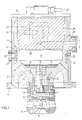
- a cooling plate 16 which is only visible in FIG. 2 and which is connected to the fastening flange 5 via a connecting line 17 formed by a web.
- the contacts 11, the connecting lines 12 and the connecting line 17 consist of a metallic material with high thermal conductivity and thereby form thermal bridges which transmit the heat given off by the hot cathode to the connecting terminals 10 and the control electrode 6 to the cooling plates 15, 16.
- the cooling plates 15, 16 essentially fill the circular bottom surface of the recess 13. They are covered at the top by a circular insulator disk 18, on which the bottom of a cup-shaped heat sink 20 lies, which completely fills the lower region of the recess 13.
- the heat sink 19 likewise consists of a material of good electrical and thermal conductivity and forms a capsule which is closed by a cover 20 and which has the effect of a Faraday cage and contains an electrical circuit arrangement for controlling the electron beam generator.
- the cooling plates 15, 16 are connected to the circuit arrangement in the capsule formed by the heat sink 19 via plug contacts 25, which extend through openings in the insulator disk 18 and in the bottom of the heat sink 19.
- the high-voltage insulator 3 has an annular recess 21 in its outer surface facing the housing 1 which is a heat exchanger 22 with a cooling channel 23 through which a cooling liquid, for example water, flows.
- the cooling duct 23 can be connected to a cooling circuit via an opening 24 in the housing 1.
- an insulating body 26 which contains an insulating transformer 27 which serves as a current transformer for the cathode heating current.
- the electron beam generator can be connected to a high voltage supply via a high voltage connection 28.
- the electron beam generator described allows for a simple and compact structure to cool the cathode carrier 8 and the control electrode 6 well by effective heat dissipation via the current feedthroughs in the high-voltage insulator 3 and the heat sink 19 which receives the electrical circuit arrangement
- the heat exchanger 22 is at earth potential and therefore makes no special demands on the cooling circuit. Since the heat transport from the jet generator to the heat exchanger is achieved exclusively by heat conduction in solids, it is effective even at low temperatures, so that the temperature of the jet generator can also be advantageously kept low.
Landscapes
- Chemical & Material Sciences (AREA)
- Analytical Chemistry (AREA)
- Electron Sources, Ion Sources (AREA)
Applications Claiming Priority (2)
| Application Number | Priority Date | Filing Date | Title |
|---|---|---|---|
| DE3930399A DE3930399A1 (de) | 1989-09-12 | 1989-09-12 | Elektronenstrahlerzeuger, insbesondere fuer eine elektronenstrahlkanone |
| DE3930399 | 1989-09-12 |
Publications (3)
| Publication Number | Publication Date |
|---|---|
| EP0417643A2 true EP0417643A2 (fr) | 1991-03-20 |
| EP0417643A3 EP0417643A3 (en) | 1991-08-14 |
| EP0417643B1 EP0417643B1 (fr) | 1995-06-07 |
Family
ID=6389239
Family Applications (1)
| Application Number | Title | Priority Date | Filing Date |
|---|---|---|---|
| EP90117161A Expired - Lifetime EP0417643B1 (fr) | 1989-09-12 | 1990-09-06 | Dispositif de production de faisceaux d'électrons, en particulier pour canon à électrons |
Country Status (3)
| Country | Link |
|---|---|
| US (1) | US5095241A (fr) |
| EP (1) | EP0417643B1 (fr) |
| DE (2) | DE3930399A1 (fr) |
Cited By (1)
| Publication number | Priority date | Publication date | Assignee | Title |
|---|---|---|---|---|
| AT524356A3 (de) * | 2020-10-19 | 2025-05-15 | Theva Duennschichttechnik Gmbh | Aktiv gekühlte Elektronenkanone zur Materialverdampfung im Vakuum |
Families Citing this family (3)
| Publication number | Priority date | Publication date | Assignee | Title |
|---|---|---|---|---|
| DE19537229C1 (de) * | 1995-10-06 | 1997-01-30 | Saechsische Elektronenstrahl G | Strahlerzeuger für eine Axial-Elektronenkanone |
| AU2010295585B2 (en) | 2009-09-17 | 2015-10-08 | Sciaky, Inc. | Electron beam layer manufacturing |
| EP2555902B1 (fr) | 2010-03-31 | 2018-04-25 | Sciaky Inc. | Méthode de balayage de trame pour la construction de pièces couche par couche à l'aide d'un faisceau d'electrons controlé en boucle fermée |
Family Cites Families (3)
| Publication number | Priority date | Publication date | Assignee | Title |
|---|---|---|---|---|
| US3329849A (en) * | 1965-03-26 | 1967-07-04 | Minnesota Mining & Mfg | Electron gun apparatus with heat sink means for supporting filament and grid |
| US3809939A (en) * | 1972-11-08 | 1974-05-07 | Varian Associates | Gridded electron tube employing cooled ceramic insulator for mounting control grid |
| DE3333686A1 (de) * | 1983-09-17 | 1985-04-04 | Leybold-Heraeus GmbH, 5000 Köln | Elektronenstrahlkanone zum erwaermen von materialien, insbesondere zum schweissen |
-
1989
- 1989-09-12 DE DE3930399A patent/DE3930399A1/de not_active Withdrawn
-
1990
- 1990-09-06 EP EP90117161A patent/EP0417643B1/fr not_active Expired - Lifetime
- 1990-09-06 DE DE59009200T patent/DE59009200D1/de not_active Expired - Fee Related
- 1990-09-10 US US07/579,790 patent/US5095241A/en not_active Expired - Lifetime
Cited By (1)
| Publication number | Priority date | Publication date | Assignee | Title |
|---|---|---|---|---|
| AT524356A3 (de) * | 2020-10-19 | 2025-05-15 | Theva Duennschichttechnik Gmbh | Aktiv gekühlte Elektronenkanone zur Materialverdampfung im Vakuum |
Also Published As
| Publication number | Publication date |
|---|---|
| DE59009200D1 (de) | 1995-07-13 |
| EP0417643A3 (en) | 1991-08-14 |
| US5095241A (en) | 1992-03-10 |
| EP0417643B1 (fr) | 1995-06-07 |
| DE3930399A1 (de) | 1991-03-14 |
Similar Documents
| Publication | Publication Date | Title |
|---|---|---|
| DE69401137T2 (de) | Kühlungsanordnung für elektrische Leistungsbauteile | |
| EP0035135B1 (fr) | Unité à semiconducteurs avec au minimum deux éléments semiconducteurs | |
| DE102019201986B4 (de) | Batteriegehäuse zur Aufnahme wenigstens eines Zellmoduls einer Traktionsbatterie | |
| EP1496534B1 (fr) | Disjoncteur à haute puissance avec assemblage d'ailettes de refroidissement | |
| DE1047950B (de) | Luftgekuehlte Leistungs-Gleichrichteranordnung mit gekapselten Halbleiter-Gleichrichterelementen | |
| DE2337694A1 (de) | Halbleitergleichrichteranordnung | |
| DE69404178T2 (de) | Verbindungsdurchführung für supraleitende Spule | |
| EP0417643B1 (fr) | Dispositif de production de faisceaux d'électrons, en particulier pour canon à électrons | |
| DE3740233C2 (fr) | ||
| DE10140328B4 (de) | Kühlanordnung zur Kühlung elektronischer Bauelemente | |
| DE3127456A1 (de) | Stromrichteranordnung | |
| EP0268081B1 (fr) | Dispositif de refroidissement pour composants semi-conducteurs | |
| EP0086483B1 (fr) | Arrangement de redresseur de puissance | |
| DE19902498C2 (de) | Vakuumschaltröhre | |
| DE2322372B2 (de) | Mehrpoliges vakuumschaltgeraet mit isolierstoffgekapselten schaltgefaessen | |
| DE3789882T2 (de) | Hochleistungsschalter. | |
| DE102021207316A1 (de) | Leistungselektronik | |
| DE1205196B (de) | Halbleiteranordnung mit mindestens einem Halbleiterbauelement | |
| EP0072478B1 (fr) | Redresseur à haute tension | |
| DE2021374C3 (de) | Leistungswiderstand | |
| CH377941A (de) | Anordnung zur Ableitkühlung einer wärmemässig stark belasteten Elektrode einer Elektronenröhre in einem Hochfrequenzgerät | |
| DE1283394B (de) | Elektrischer Kondensator mit einem wenigstens an einem Ende offenen, im wesentlichen zylinderfoermigen Koerper aus formfestem dielektrischem Material | |
| DE1085263B (de) | Gleichrichteraufbau mit einem Halbleiterkoerper | |
| DE4242699A1 (en) | Power resistor for chassis mounting - has resistive element between two insulating layers which are pressed between metal plates forming housing. | |
| EP4084189A1 (fr) | Batterie de traction d'un véhicule automobile |
Legal Events
| Date | Code | Title | Description |
|---|---|---|---|
| PUAI | Public reference made under article 153(3) epc to a published international application that has entered the european phase |
Free format text: ORIGINAL CODE: 0009012 |
|
| AK | Designated contracting states |
Kind code of ref document: A2 Designated state(s): DE FR GB |
|
| PUAL | Search report despatched |
Free format text: ORIGINAL CODE: 0009013 |
|
| AK | Designated contracting states |
Kind code of ref document: A3 Designated state(s): DE FR GB |
|
| 17P | Request for examination filed |
Effective date: 19920113 |
|
| 17Q | First examination report despatched |
Effective date: 19940201 |
|
| GRAA | (expected) grant |
Free format text: ORIGINAL CODE: 0009210 |
|
| AK | Designated contracting states |
Kind code of ref document: B1 Designated state(s): DE FR GB |
|
| GBT | Gb: translation of ep patent filed (gb section 77(6)(a)/1977) |
Effective date: 19950612 |
|
| REF | Corresponds to: |
Ref document number: 59009200 Country of ref document: DE Date of ref document: 19950713 |
|
| ET | Fr: translation filed | ||
| PLBE | No opposition filed within time limit |
Free format text: ORIGINAL CODE: 0009261 |
|
| STAA | Information on the status of an ep patent application or granted ep patent |
Free format text: STATUS: NO OPPOSITION FILED WITHIN TIME LIMIT |
|
| 26N | No opposition filed | ||
| REG | Reference to a national code |
Ref country code: GB Ref legal event code: IF02 |
|
| PGFP | Annual fee paid to national office [announced via postgrant information from national office to epo] |
Ref country code: GB Payment date: 20080926 Year of fee payment: 19 |
|
| PGFP | Annual fee paid to national office [announced via postgrant information from national office to epo] |
Ref country code: DE Payment date: 20080925 Year of fee payment: 19 |
|
| PGFP | Annual fee paid to national office [announced via postgrant information from national office to epo] |
Ref country code: FR Payment date: 20080926 Year of fee payment: 19 |
|
| GBPC | Gb: european patent ceased through non-payment of renewal fee |
Effective date: 20090906 |
|
| REG | Reference to a national code |
Ref country code: FR Ref legal event code: ST Effective date: 20100531 |
|
| PG25 | Lapsed in a contracting state [announced via postgrant information from national office to epo] |
Ref country code: DE Free format text: LAPSE BECAUSE OF NON-PAYMENT OF DUE FEES Effective date: 20100401 Ref country code: FR Free format text: LAPSE BECAUSE OF NON-PAYMENT OF DUE FEES Effective date: 20090930 |
|
| PG25 | Lapsed in a contracting state [announced via postgrant information from national office to epo] |
Ref country code: GB Free format text: LAPSE BECAUSE OF NON-PAYMENT OF DUE FEES Effective date: 20090906 |