EP0418258B1 - Unite de commande du braquage des roues arriere de vehicules de voirie - Google Patents
Unite de commande du braquage des roues arriere de vehicules de voirie Download PDFInfo
- Publication number
- EP0418258B1 EP0418258B1 EP19890905389 EP89905389A EP0418258B1 EP 0418258 B1 EP0418258 B1 EP 0418258B1 EP 19890905389 EP19890905389 EP 19890905389 EP 89905389 A EP89905389 A EP 89905389A EP 0418258 B1 EP0418258 B1 EP 0418258B1
- Authority
- EP
- European Patent Office
- Prior art keywords
- emergency
- steering
- computers
- control unit
- signals
- Prior art date
- Legal status (The legal status is an assumption and is not a legal conclusion. Google has not performed a legal analysis and makes no representation as to the accuracy of the status listed.)
- Expired - Lifetime
Links
- 238000011156 evaluation Methods 0.000 claims abstract description 13
- 230000001419 dependent effect Effects 0.000 claims abstract 2
- 238000012360 testing method Methods 0.000 claims description 10
- 238000003745 diagnosis Methods 0.000 claims description 6
- 230000004913 activation Effects 0.000 claims description 2
- 230000011664 signaling Effects 0.000 claims description 2
- 101150035438 Ist1 gene Proteins 0.000 abstract description 2
- 210000000056 organ Anatomy 0.000 description 21
- 238000012544 monitoring process Methods 0.000 description 11
- 238000012545 processing Methods 0.000 description 9
- 238000000034 method Methods 0.000 description 6
- 230000007547 defect Effects 0.000 description 3
- 230000007257 malfunction Effects 0.000 description 3
- 230000008569 process Effects 0.000 description 3
- 238000001994 activation Methods 0.000 description 2
- 230000008901 benefit Effects 0.000 description 2
- 230000008859 change Effects 0.000 description 2
- 230000001934 delay Effects 0.000 description 2
- 230000003111 delayed effect Effects 0.000 description 2
- 230000000903 blocking effect Effects 0.000 description 1
- 238000001514 detection method Methods 0.000 description 1
- 238000011161 development Methods 0.000 description 1
- 230000018109 developmental process Effects 0.000 description 1
- 239000012530 fluid Substances 0.000 description 1
- 238000012423 maintenance Methods 0.000 description 1
- 230000007935 neutral effect Effects 0.000 description 1
- 230000004044 response Effects 0.000 description 1
- 230000007704 transition Effects 0.000 description 1
- 230000001960 triggered effect Effects 0.000 description 1
Images

Classifications
-
- B—PERFORMING OPERATIONS; TRANSPORTING
- B62—LAND VEHICLES FOR TRAVELLING OTHERWISE THAN ON RAILS
- B62D—MOTOR VEHICLES; TRAILERS
- B62D7/00—Steering linkage; Stub axles or their mountings
- B62D7/06—Steering linkage; Stub axles or their mountings for individually-pivoted wheels, e.g. on king-pins
- B62D7/14—Steering linkage; Stub axles or their mountings for individually-pivoted wheels, e.g. on king-pins the pivotal axes being situated in more than one plane transverse to the longitudinal centre line of the vehicle, e.g. all-wheel steering
- B62D7/15—Steering linkage; Stub axles or their mountings for individually-pivoted wheels, e.g. on king-pins the pivotal axes being situated in more than one plane transverse to the longitudinal centre line of the vehicle, e.g. all-wheel steering characterised by means varying the ratio between the steering angles of the steered wheels
- B62D7/159—Steering linkage; Stub axles or their mountings for individually-pivoted wheels, e.g. on king-pins the pivotal axes being situated in more than one plane transverse to the longitudinal centre line of the vehicle, e.g. all-wheel steering characterised by means varying the ratio between the steering angles of the steered wheels characterised by computing methods or stabilisation processes or systems, e.g. responding to yaw rate, lateral wind, load, road condition
-
- B—PERFORMING OPERATIONS; TRANSPORTING
- B62—LAND VEHICLES FOR TRAVELLING OTHERWISE THAN ON RAILS
- B62D—MOTOR VEHICLES; TRAILERS
- B62D7/00—Steering linkage; Stub axles or their mountings
- B62D7/06—Steering linkage; Stub axles or their mountings for individually-pivoted wheels, e.g. on king-pins
- B62D7/14—Steering linkage; Stub axles or their mountings for individually-pivoted wheels, e.g. on king-pins the pivotal axes being situated in more than one plane transverse to the longitudinal centre line of the vehicle, e.g. all-wheel steering
- B62D7/148—Steering linkage; Stub axles or their mountings for individually-pivoted wheels, e.g. on king-pins the pivotal axes being situated in more than one plane transverse to the longitudinal centre line of the vehicle, e.g. all-wheel steering provided with safety devices
-
- G—PHYSICS
- G05—CONTROLLING; REGULATING
- G05B—CONTROL OR REGULATING SYSTEMS IN GENERAL; FUNCTIONAL ELEMENTS OF SUCH SYSTEMS; MONITORING OR TESTING ARRANGEMENTS FOR SUCH SYSTEMS OR ELEMENTS
- G05B9/00—Safety arrangements
- G05B9/02—Safety arrangements electric
- G05B9/03—Safety arrangements electric with multiple-channel loop, i.e. redundant control systems
Definitions
- the invention relates to a control unit according to the preamble of claim 1.
- a control unit (EP-A 0 243 180, US-A 4 687 214) is used in motor vehicles with all-wheel steering to act on the latter in the event of a failure of the rear-wheel steering so that driving safety the motor vehicle remains guaranteed.
- Such an emergency can e.g. are caused by the fact that various sensors in the motor vehicle, the signals of which are evaluated for the rear wheel steering, fail, that components fail in the control unit for the rear wheel steering or that cable breaks occur.
- the emergency operation is controlled by a microcomputer or by a discrete electronic circuit. It cannot be ruled out that even errors and failures can occur in such a control.
- the invention has for its object to increase the safety of a control unit for steering the rear wheels of a motor vehicle in an emergency.
- both the rear wheel steering angle can be rigidly maintained by blocking the steering, and the rear wheel steering can be transferred to its starting or neutral position and locked there.
- the fault tolerance of the control unit is increased by preventing it from not issuing a steering emergency signal because of a faulty computer, even though an emergency actually exists. Critical driving situations are thus reliably prevented.
- the concept on which the invention is based also differs from other double computer systems known from various areas of technology. For example, Systems with a test or comparator unit that compares the results of the two computers. The invention avoids both the time delays caused by the comparison and the risk that the comparator unit itself is faulty. In the worst case, an unnecessary steering emergency signal can be given, i.e. with the control unit according to the invention you are always on the safe side.
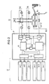
- the steering device LE contains, by way of example, a hydraulic clamping device Noh which, in an emergency, blocks the steering of the rear wheels in such a way that the steering angle present up to that point remains rigid, by hydraulically preventing any change in the steering angle by means of corresponding braking or clamping devices becomes.
- the steering device LE contains an actuator Sa, which adjusts the steering angle of the rear wheels in normal operation.
- the computers P1, P2 also control the steering wheel angle of the rear wheels in normal operation, precisely by means of the actuating unit Sa. Therefore, in this example, the computers intervene not only in the steering angle control of the rear wheels in an emergency, but also in normal operation.
- the steering device LE contains one or more lamps L which signal the normal operation and the malfunction to the driver and e.g. can also display the current value of the steering angle.
- the steering device LE additionally contains a monitoring unit Sv which, e.g. by means of own sensors and / or triggered by a steering emergency signal, the occurrence of errors in the steering device LE - possibly also in other parts of the control unit and / or in other parts of the road vehicle - is monitored.
- This monitoring unit Sv can react if necessary, e.g. can trigger a reset, which interrupts the evaluation by the computers and causes the computers to restart their evaluation or in some other way delivers a corresponding monitoring signal - preferably to the computers P1, P2.
- the steering device LE additionally contains, in a redundant manner, a mechanical clamping device Nom, which, in a purely mechanical manner, rigidly maintains the steering angle of the rear wheels that was given up to that point.
- the steering device LE therefore contains two emergency organs formed by Noh / Nom, each of which, in an emergency, controls the steering angle according to the selected emergency operating concept - in the present case, therefore, by clamping the steering - in an emergency.
- the individual organs of the steering device LE have their own signal outputs St for their monitoring, which thus supply test signals or status signals and in the example shown are connected to signal inputs St of a preamplifier stage VV of the computers P1, P2.
- sensors or the analog-to-digital converters assigned to such sensors are additionally attached, e.g. electronic units, which state the condition of a steering wheel angle sensor Lwl, an automatic braking system ABS, the speed tach, the safety doubled status outputs Ist 1,2 of the actuator Sa, the safety double wheel steering angle sensors Lwr1,2, other status monitoring stat and other inputs Se - e.g. for the outside temperature, the tire temperature and / or the light reflection of the more or less reflective road surface.
- This preamplifier unit VV does not necessarily include only the sensors themselves, but often also electronic components of the same, which the sensor signals supplied by sensors, cf. Ss, convert or convert more or less and deliver control signals at their output, which the two computers P1, P2 directly or via intermediate stages - cf. Ael to Ae3 - are fed.
- the control signals for evaluation - i.e. to calculate a calculation result
- Both computers P1, P2 process the control signals supplied to them digitally in the example shown, in accordance with programs that they store. These programs often contain instructions that correspond to complicated differential equations and associated, sometimes quite lengthy iterative procedures. From the control signals Ss, Lw1, Lwr1 / 2, ABS, Tach, Ist1 / 2, St, Se, these programs are used to process computing results with sometimes less, but often a relatively large amount of time, the computing results despite the high computing clock frequency in the MHz range often only after 10 msec or 40 msec.
- Each computer P1, P2 for itself derives from its own calculation results whether there is an emergency or not.
- the computer in question immediately delivers its steering emergency signal immediately without comparing its calculation result with the calculation result of the other computer - possibly amplified via intermediate amplifier Zv, cf. 2 - from the steering device LE, in accordance with the case shown in FIG. 1 immediately to both the hydraulic clamping device Noh and the mechanical clamping device Nom.
- both computers P1, P2 simultaneously determine that an emergency has just occurred, both computers P1, P2 simultaneously simultaneously deliver their steering emergency signal individually to the relevant organs Noh / Nom of the steering device LE. If first the one computer and only after a certain delay - or never - the other computer recognizes the occurrence of the emergency, there is at least a certain time difference between the delivery of their individual steering emergency signals. The emergency organs Noh / Nom are then already activated by the first steering emergency signal, because in order to avoid time delays there is no waiting in the invention - e.g. with the aid of a comparator unit connected downstream of the two computers P1, P2 - until both computers P1, P2 signaled the occurrence of the emergency.
- the invention thus prevents a malfunctioning computer from the arithmetic unit erroneously not emitting a steering emergency signal, whether an emergency is due, because in the invention the other of the two computers recognizes the emergency and in turn immediately sends its steering emergency signal immediately and directly to the emergency organs Noh / Nom emits and triggers the control of the steering angle of the rear wheels according to the selected emergency operating concept.
- the invention is not tied to a special emergency operation concept: e.g. that in an emergency, the steering angle of the rear wheels, as previously described, is rigidly maintained.
- the emergency organs Noh / Nom other types of emergency organs can be attached, which in an emergency e.g. the more or less delayed setting of the steering angle zero of the rear wheels triggers.
- the invention is therefore a new type of safety concept which can be used in addition to any emergency operating concept and is used to further improve control of the road vehicle in an emergency.
- the invention increases the fault tolerance of the control unit, in particular by preventing a faulty computer from mistakenly not issuing a steering emergency signal, even though there is an emergency - a particularly dangerous situation which could lead to very serious accidents of the road vehicle.
- the invention allows the steering emergency signal to be emitted particularly quickly in an emergency and the measures to be initiated immediately in accordance with the selected emergency operating concept.
- the exemplary embodiment shown in FIG. 2 is constructed and operated very similarly to the one shown in FIG.
- sensor units are attached, each of which already contains electronic components, at least in part, so that the preamplifier unit VV is, so to speak, broken down into individual parts and contained in the sensor units.
- These sensor units represent, for example, duplicated steering wheel angle sensor units Lwl 1/2, where one sensor Lwll, for example the steering angle on the steering column and the other steering wheel angle sensor Lw12 may be attached, for example, to the steering gear and / or to parts of the steering of the front wheels.
- double rear wheel steering angle sensor units Lwr1 / 2 are attached, which measure the rear wheel steering angle on both rear wheels and / or indirectly on associated steering rods and / or steering gear parts, for example, separately from one another.
- sensor units Tach and ABS attached to record the vehicle speed and the braking system.
- the example shown in FIG. 2 again contains two computers P1, P2, the signals from the sensors, i.e. the control signals supplied to the computers, as in the example shown in FIG. 1, are evaluated in the two computers P1, P2.
- the example shown in FIG. 2 contains power amplifiers as intermediate amplifiers Zv, which in turn then control the steering device LE, the steering device LE here working, for example, according to a hydraulic method.
- the hydraulic fluid Hy acts via mechanical safety valves Vm, via hydraulic safety valves Vh and servo valves Vs on hydraulically controlled steering angle influencing units of the rear wheels, one of which, denoted by H, is symbolically indicated with parts of its steering linkage.
- Sensors Lwr1 / 2 are shown as an example, which indirectly detect the steering angle of the rear wheels H.
- the fault tolerance of the control unit is increased by preventing, according to the invention, that the computing unit does not mistakenly emit no steering emergency signal, even though there is an emergency, with each of the two computers, independently of the other computer, immediately giving its steering emergency signal to the steering device in an emergency.
- the computers P1, P2 can, as in the example shown in FIG. 1, test signals and / or status signals St - cf. 1, not shown in FIG. 2 - are supplied to the control unit by components, the computer P1 and / or P2 in question as soon as it detects components, e.g. one of the doubled sensors or an emergency organ Noh / Nom or one of the computers P1, P2 itself determined, in any case for safety's sake emits a steering emergency signal to the steering motor organs which are doubled or not doubled here in order to increase the safety of the road vehicle. In this way, even in the example shown in FIG.
- the dangerous situation is avoided that the reliability of the control unit is considerably reduced in the event of significant defects or faulty states of the relevant components.
- the driver of the road vehicle can be stopped, in particular by signaling lamps L, to visit a workshop as soon as possible in order to have the defect in the relevant components eliminated.
- the steering device LE contains at least two emergency operations Noh / Nom in a redundant manner, each of which independently controls the steering angle in an emergency in accordance with the selected emergency operating concept in an emergency. This makes it possible that, despite a defect in one of these two emergency organs, the steering emergency signal emitted by the computer reliably triggers an emergency-appropriate control of the steering of the rear wheels, because in this case the still functioning properly other emergency organ triggers the emergency-appropriate control in turn.
- each computer transmits its steering emergency signal - at least as a rule - to both emergency organs Noh / Nom, specifically via its own steering emergency signal lines assigned to the individual computers P1 / P2.
- a break or other malfunction on such a steering emergency signal line, as well as the complete failure of one of the computers, does not then hinder the emergency-appropriate control of the steering of the rear wheels.
- both emergency organs can initially be operated as in an emergency.
- the safety of the road vehicle is then also increased at the start, in which some of the sensor signals, cf. e.g. Ss, do not yet represent any useful values and reliable evaluation by the two computers is often still impossible.
- the monitoring unit Sv mentioned above, cf. 1 can in turn compare a subsequent comparison between the two computers - in particular between their relevant intermediate results and final results of the evaluations - and, if necessary, interrupt the computers by means of the interrupt signal IntR, e.g. to run special self-test programs in the two computers and to subsequently restart the computers with a reset start signal.
- this monitoring unit Sv e.g. restart the computer or computers by means of a watch dog and the reset signal.
- monitoring unit Sv it is not necessary to install such a monitoring unit Sv. Instead, such monitoring can also be carried out from time to time within the computers P1, P2, e.g. with the help of a watch dog and direct lines DL, especially if the computers have memory areas in them into which the other computer is actively writing and from which the other computer can be actively reading without interrupting the operation of the passive computer.
- the information can also be temporarily stored in the dual-port RAM DPR, for example that each computer P1, P2 has a memory area there, in which it can write and read itself and the other computer can only read.
- each computer P1, P2 has a memory area there, in which it can write and read itself and the other computer can only read.
- This is indicated by the special type of arrows between the computers P1, P2 and the relevant memory DPR.
- this memory DPR can additionally have a special memory area which can be read and (!) Written by both computers P1, P2 as desired.
- the memory DPR has the advantage that the computers can even work asynchronously, at least clock-shifted, without the computers delaying each other through the comparison and hindering the rapid immediate generation of the steering emergency signal.
- the computers can thus - especially after a steering emergency signal has been given and / or after the detection of a status signal St of any component corresponding to an error, cf. Noh, Sa, L, Sv, Nom - so prompted for error diagnosis, for which both computers can be stopped. As soon as the diagnosis is made and e.g. Both computers are finally restarted via the Diag unit.
- the steering device LE should only go into normal operation when the control signals and / or the information given indicate that there is no emergency.
- each computer is preferably assigned a different emergency organ of the two emergency organs individually until the checking of the emergency organs finally signals that they are free of errors. After the transition to normal operation, each computer delivers its steering emergency signal directly to both emergency organs in an emergency. It can thus be ensured in a relatively clear manner that the computers and more or less checked all the essential organs of the control unit before normal operation, i.e. for normal steering of the rear wheels.
- the computers can work synchronously. However, an operation is preferred in which the two computers work synchronously, but shifted in time by approximately half an evaluation period. If the evaluation period of a computer is e.g. lasts an average of 20 msec, then the optimal time shift is approximately 10 msec. In this way it can be achieved that one computer is already emitting its steering emergency signal, while the other has not yet completed its evaluation. Such a control unit therefore reacts particularly quickly in an emergency, as long as both computers are working properly.
- the reliability of the control unit can also be increased in other ways.
- the computers can be equipped differently in terms of software and / or hardware and then even operated asynchronously.
- many consequences of software errors and hardware errors become harmless, especially if one of the two computers gets lost due to different programs, whereas the other computer, due to its program, still achieves a calculation result that it has accepted relatively quickly.
- Such an asynchronous mode of operation of both computers which is made possible in particular by software and / or hardware differences, means that both computers can work very flexibly in accordance with their respective time requirements for evaluating the control signals, which can greatly increase the response speed of the control unit, especially in critical situations .
- the sensors can also be attached several times in a redundant manner and therefore also measure the same physical quantity in a redundant but, in principle, very different manner.
- E.g. steering angle deflections can be measured once in the immediate vicinity of the wheels in question and then redundantly in addition close to the steering gear parts.
- Processing units can also be used in between - cf. Insert Ae1, Ae2, Ae3 in FIG. 1 and Ae in FIG. 2 into the feeds that pre-process the control signals, e.g. convert into parameters that can be derived from the sensor signals, and / or work out a common control signal from different sensor signals.
- Such processing units enable the computers P1, P2 to work for themselves in a particularly rapid evaluation period, which further increases the reliability of the control unit.
- processing units can send their results separately to the computer, cf. AE1, AE2 in FIG 1, or together to both computers, cf. Pass Ae3 in FIG 1 and Ae in FIG 2. If you Passing on their results to both computers, the load on the two computers is achieved with particularly little hardware effort - and when this processing unit is then doubled, cf. 2, mutual monitoring or a worst-case selection by the computers is possible, and the computers, even if one of the two processing units is working incorrectly, still very reliably and quickly emit their steering emergency signal if necessary.
- Diag diagnostic unit can be used later in the maintenance of the road vehicle to determine the cause of malfunctions in the control unit, e.g. if necessary, the deviations between the two processing units can be determined in more detail.
- sensors which are mounted redundantly can be connected to the processing units in such a way that one sensor is connected to one processing unit and the other sensor to the other processing unit, cf. e.g. FIG 2.
- This allows, for example, the causes of different sensor signals from related redundant sensors, e.g. by means of the unit Diag or e.g. by the computer itself or by the monitoring unit Sv - cf. FIG 1 - to be determined.
Landscapes
- Engineering & Computer Science (AREA)
- Physics & Mathematics (AREA)
- Chemical & Material Sciences (AREA)
- Combustion & Propulsion (AREA)
- Transportation (AREA)
- Mechanical Engineering (AREA)
- General Physics & Mathematics (AREA)
- Automation & Control Theory (AREA)
- Mathematical Physics (AREA)
- Theoretical Computer Science (AREA)
- Steering Control In Accordance With Driving Conditions (AREA)
- Steering-Linkage Mechanisms And Four-Wheel Steering (AREA)
Abstract
Claims (10)
Applications Claiming Priority (3)
| Application Number | Priority Date | Filing Date | Title |
|---|---|---|---|
| DE3816254A DE3816254A1 (de) | 1988-05-11 | 1988-05-11 | Steuereinheit zur lenkung der hinterraeder eines strassenfahrzeuges |
| DE3816254 | 1988-05-11 | ||
| PCT/DE1989/000293 WO1989010865A1 (fr) | 1988-05-11 | 1989-05-10 | Unite de commande du braquage des roues arriere de vehicules de voirie |
Publications (3)
| Publication Number | Publication Date |
|---|---|
| EP0418258A1 EP0418258A1 (fr) | 1991-03-27 |
| EP0418258B1 true EP0418258B1 (fr) | 1992-04-29 |
| EP0418258B2 EP0418258B2 (fr) | 1996-08-28 |
Family
ID=6354250
Family Applications (1)
| Application Number | Title | Priority Date | Filing Date |
|---|---|---|---|
| EP89905389A Expired - Lifetime EP0418258B2 (fr) | 1988-05-11 | 1989-05-10 | Unite de commande du braquage des roues arriere de vehicules de voirie |
Country Status (4)
| Country | Link |
|---|---|
| EP (1) | EP0418258B2 (fr) |
| JP (1) | JP2513878B2 (fr) |
| DE (2) | DE3816254A1 (fr) |
| WO (1) | WO1989010865A1 (fr) |
Families Citing this family (27)
| Publication number | Priority date | Publication date | Assignee | Title |
|---|---|---|---|---|
| DE3608391A1 (de) * | 1985-11-15 | 1987-09-17 | Messwandler Bau Ag | Hochspannungsstromwandler |
| JPH07117407B2 (ja) * | 1989-06-02 | 1995-12-18 | 三菱電機株式会社 | 車両の後輪操舵装置 |
| JPH0310968A (ja) * | 1989-06-06 | 1991-01-18 | Mitsubishi Electric Corp | 車両のハンドル操作状態検出装置 |
| DE4020568A1 (de) * | 1990-06-28 | 1992-01-02 | Bayerische Motoren Werke Ag | Verfahren zum betrieb einer lenkeinrichtung fuer die hinterraeder eines kraftfahrzeugs |
| DE4020567A1 (de) * | 1990-06-28 | 1992-01-02 | Bayerische Motoren Werke Ag | Verfahren zum betrieb einer lenkeinrichtung fuer die hinterraeder eines kraftfahrzeugs |
| DE4102492A1 (de) * | 1991-01-29 | 1992-07-30 | Zahnradfabrik Friedrichshafen | Elektromotorische antriebseinheit zur betaetigung einer elektromechanischen hinterradlenkung von kraftfahrzeugen |
| DE4124987A1 (de) * | 1991-07-27 | 1993-01-28 | Bosch Gmbh Robert | System zur ansteuerung sicherheitsrelevanter systeme |
| IT1250831B (it) * | 1991-07-31 | 1995-04-21 | Fiat Auto Spa | Sistema per il controllo in sicurezza intrinseca della sterzatura delle ruote posteriori di un autoveicolo. |
| DE4136338A1 (de) * | 1991-11-05 | 1993-05-06 | Robert Bosch Gmbh, 7000 Stuttgart, De | Verfahren und vorrichtung zur fehlerbehandlung in elektronischen steuergeraeten |
| DE59302720D1 (de) * | 1992-03-31 | 1996-07-04 | Rexroth Mannesmann Gmbh | Hinterachslenkvorrichtung für ein Kraftfahrzeug |
| DE59207291D1 (de) * | 1992-06-16 | 1996-11-07 | Siemens Ag | Elektro-hydraulische Stellvorrichtung, insbesondere für eine Kraftfahrzeug-Hinterachslenkung |
| US5504679A (en) * | 1993-02-15 | 1996-04-02 | Mitsubishi Denki Kabushiki Kaisha | Control apparatus for motor-driven power steering system of motor vehicle |
| FR2704329B1 (fr) * | 1993-04-21 | 1995-07-13 | Csee Transport | Système de sécurité à microprocesseur, applicable notamment au domaine des transports ferroviaires. |
| DE59309309D1 (de) * | 1993-07-27 | 1999-02-25 | Siemens Ag | Schaltungsanordnung zum Ermitteln der Temperatur einer stromgeregelten elektrischen Spule |
| EP0742505A3 (fr) * | 1995-05-11 | 1998-01-14 | Siemens Aktiengesellschaft | Dispositif de surveillance orientée sûreté d'une machine |
| JP2938806B2 (ja) * | 1996-05-27 | 1999-08-25 | 本田技研工業株式会社 | 車両用舵角制御装置 |
| DE19946074B4 (de) * | 1999-09-25 | 2008-10-16 | Volkswagen Ag | Elektrohydraulische Lenkung eines Fahrzeuges |
| DE19946073A1 (de) | 1999-09-25 | 2001-05-10 | Volkswagen Ag | System zur Steuerung von Fahrzeugkomponenten nach dem "Drive By Wire"-Prinzip |
| DE10340369B4 (de) * | 2003-09-02 | 2012-01-19 | Zf Lenksysteme Gmbh | Verfahren zur Steuerung mindestens einer mechanischen Stelleinrichtung |
| FR2864001B1 (fr) * | 2003-12-18 | 2007-11-23 | Renault Sas | Procede et systeme de commande du braquage de roue arriere directrice et vehicule correspondant |
| NL1037275C2 (nl) * | 2009-09-11 | 2011-03-14 | Advanced Public Transp Systems B V | Stuurinrichting voor een vooraf gedefinieerd traject verplaatsbaar voertuig, automatisch gestuurd en via tenminste een eerste as , alsmede een voertuig voorzien van een dergelijke stuurinrichting. |
| KR101770865B1 (ko) | 2013-08-20 | 2017-08-23 | 주식회사 만도 | 능동형 후륜 조향장치 제어방법 |
| DE102014117411A1 (de) * | 2014-11-27 | 2016-06-02 | Hella Kgaa Hueck & Co. | Logikschaltkreis zum Halten des Schaltzustands von Schaltausgängen |
| DE102016109089B4 (de) * | 2016-05-18 | 2024-04-25 | Robert Bosch Gmbh | Steuergerät zur Verarbeitung von Sensorsignalen |
| DE102018129119A1 (de) * | 2018-11-20 | 2020-04-02 | Schaeffler Technologies AG & Co. KG | Fahrwerksaktuator für eine Hinterachslenkung |
| DE102019120028A1 (de) * | 2019-07-24 | 2021-01-28 | Schaeffler Technologies AG & Co. KG | Schaltungseinrichtung zur Ansteuerung eines Motors |
| DE202020104388U1 (de) * | 2020-07-29 | 2020-08-17 | TECO GbmH transport engineering consulting | Hydrostatische Lenkvorrichtung |
Family Cites Families (6)
| Publication number | Priority date | Publication date | Assignee | Title |
|---|---|---|---|---|
| US4621327A (en) * | 1984-06-13 | 1986-11-04 | Nartron Corporation | Electronic power steering method and apparatus |
| JPS6182201A (ja) * | 1984-09-29 | 1986-04-25 | Nec Home Electronics Ltd | フエイルセ−フ制御回路 |
| US4799159A (en) * | 1985-05-30 | 1989-01-17 | Honeywell Inc. | Digital automatic flight control system with disparate function monitoring |
| JPS6234861A (ja) | 1985-08-06 | 1987-02-14 | Nissan Motor Co Ltd | 車両の4輪操舵装置 |
| DE3539407A1 (de) * | 1985-11-07 | 1987-05-14 | Bosch Gmbh Robert | Rechnersystem mit zwei prozessoren |
| JPS62251277A (ja) * | 1986-04-22 | 1987-11-02 | Mitsubishi Electric Corp | 電動式後輪操舵装置 |
-
1988
- 1988-05-11 DE DE3816254A patent/DE3816254A1/de not_active Withdrawn
-
1989
- 1989-05-10 WO PCT/DE1989/000293 patent/WO1989010865A1/fr not_active Ceased
- 1989-05-10 DE DE8989905389T patent/DE58901285D1/de not_active Expired - Lifetime
- 1989-05-10 JP JP1505096A patent/JP2513878B2/ja not_active Expired - Lifetime
- 1989-05-10 EP EP89905389A patent/EP0418258B2/fr not_active Expired - Lifetime
Also Published As
| Publication number | Publication date |
|---|---|
| JP2513878B2 (ja) | 1996-07-03 |
| DE58901285D1 (de) | 1992-06-04 |
| EP0418258B2 (fr) | 1996-08-28 |
| WO1989010865A1 (fr) | 1989-11-16 |
| DE3816254A1 (de) | 1989-11-23 |
| JPH03504362A (ja) | 1991-09-26 |
| EP0418258A1 (fr) | 1991-03-27 |
Similar Documents
| Publication | Publication Date | Title |
|---|---|---|
| EP0418258B1 (fr) | Unite de commande du braquage des roues arriere de vehicules de voirie | |
| EP0610316B1 (fr) | Procede et dispositif pour le traitement d'erreurs dans des appareils de commande electroniques | |
| DE102004026594B4 (de) | Kraftfahrzeug mit redundantem Steuergerät | |
| DE4334260C2 (de) | Steuervorrichtung für ein Fahrzeug mit einer Antiblockier-Bremseinrichtung und einer Servolenkeinrichtung | |
| DE3518105C2 (fr) | ||
| DE102014220781A1 (de) | Ausfallsichere E/E-Architektur für automatisiertes Fahren | |
| EP0892732B1 (fr) | Procede et dispositif permettant de commander la repartition de la force de freinage d'un vehicule automobile | |
| EP1349759A1 (fr) | Dispositif de controle de moyens detecteurs agences dans un vehicule | |
| EP0525574A2 (fr) | Système pour commander des systèmes de sécurité | |
| DE3903071A1 (de) | Verfahren zum pruefen eines satzes von radgeschwindigkeitssensoren, die teil eines antiblockierbremssystems sind | |
| DE19500188B4 (de) | Schaltungsanordnung für eine Bremsanlage | |
| EP1053153B1 (fr) | Procede pour le traitement d'erreurs dans un systeme de freinage electronique et dispositif associe | |
| WO2008028648A2 (fr) | Système d'entraînement et procédé pour surveiller un mécanisme d'entraînement hydrostatique | |
| DE102017109175A1 (de) | Steuereinrichtung, Fahrerassistenzsystem, Kraftfahrzeug und Verfahren zum Steuern einer Fahrerassistenzfunktion | |
| EP3470301B1 (fr) | Système de commande de direction pour un système de direction d'un véhicule automobile ainsi qu'un procédé de fonctionnement d'un système de commande de direction | |
| WO2020200599A1 (fr) | Procédé et dispositif de commande d'au moins un actionneur d'un système d'actionneur | |
| DE102018121396A1 (de) | Funktionelles Redundanzmanagementsystem für Fahrzeuge und Verfahren zum funktionellen Redundanzmanagement | |
| DE19944939C1 (de) | Steuergerät für ein Kraftfahrzeug | |
| DE4302482B4 (de) | Verfahren zur Prüfung eines elektronischen Steuergerätes mit Hilfe eines externen Diagnosegerätes | |
| EP3468849B1 (fr) | Procédé de surveillance d'une régulation abs dans un système de freinage à commande électrique et système de freinage à commande électronique | |
| EP2559602A2 (fr) | Procédé et dispositif destiné à bloquer la traction d'un véhicule ferroviaire arrêté | |
| EP1614604A1 (fr) | Procédé de changement entre un premier et un deuxième système de commande de trains | |
| DE102022213783B4 (de) | Verfahren zur Plausibilisierung eines Parameters | |
| DE102015119611B4 (de) | Verbesserung der Diagnostizierbarkeit von Fail-operational Systemen | |
| DE102024100096B4 (de) | System, insbesondere Lenksystem, für ein Fahrzeug; Verfahren zum Betrieb eines Systems, insbesondere Lenksystems, für ein Fahrzeug |
Legal Events
| Date | Code | Title | Description |
|---|---|---|---|
| PUAI | Public reference made under article 153(3) epc to a published international application that has entered the european phase |
Free format text: ORIGINAL CODE: 0009012 |
|
| 17P | Request for examination filed |
Effective date: 19900625 |
|
| AK | Designated contracting states |
Kind code of ref document: A1 Designated state(s): DE FR GB IT |
|
| 17Q | First examination report despatched |
Effective date: 19910614 |
|
| GRAA | (expected) grant |
Free format text: ORIGINAL CODE: 0009210 |
|
| AK | Designated contracting states |
Kind code of ref document: B1 Designated state(s): DE FR GB IT |
|
| REF | Corresponds to: |
Ref document number: 58901285 Country of ref document: DE Date of ref document: 19920604 |
|
| ET | Fr: translation filed | ||
| ITF | It: translation for a ep patent filed | ||
| GBT | Gb: translation of ep patent filed (gb section 77(6)(a)/1977) | ||
| PLBI | Opposition filed |
Free format text: ORIGINAL CODE: 0009260 |
|
| 26 | Opposition filed |
Opponent name: ROBERT BOSCH GMBH Effective date: 19930129 |
|
| RAP4 | Party data changed (patent owner data changed or rights of a patent transferred) |
Owner name: BAYERISCHE MOTOREN WERKE AKTIENGESELLSCHAFT Owner name: SIEMENS AKTIENGESELLSCHAFT |
|
| APAC | Appeal dossier modified |
Free format text: ORIGINAL CODE: EPIDOS NOAPO |
|
| PLAW | Interlocutory decision in opposition |
Free format text: ORIGINAL CODE: EPIDOS IDOP |
|
| PUAH | Patent maintained in amended form |
Free format text: ORIGINAL CODE: 0009272 |
|
| STAA | Information on the status of an ep patent application or granted ep patent |
Free format text: STATUS: PATENT MAINTAINED AS AMENDED |
|
| 27A | Patent maintained in amended form |
Effective date: 19960828 |
|
| AK | Designated contracting states |
Kind code of ref document: B2 Designated state(s): DE FR GB IT |
|
| ET3 | Fr: translation filed ** decision concerning opposition | ||
| ITF | It: translation for a ep patent filed | ||
| GBTA | Gb: translation of amended ep patent filed (gb section 77(6)(b)/1977) |
Effective date: 19891224 |
|
| PGFP | Annual fee paid to national office [announced via postgrant information from national office to epo] |
Ref country code: GB Payment date: 19970418 Year of fee payment: 9 |
|
| PGFP | Annual fee paid to national office [announced via postgrant information from national office to epo] |
Ref country code: FR Payment date: 19970521 Year of fee payment: 9 |
|
| PGFP | Annual fee paid to national office [announced via postgrant information from national office to epo] |
Ref country code: DE Payment date: 19970721 Year of fee payment: 9 |
|
| PG25 | Lapsed in a contracting state [announced via postgrant information from national office to epo] |
Ref country code: GB Free format text: LAPSE BECAUSE OF NON-PAYMENT OF DUE FEES Effective date: 19980510 |
|
| PG25 | Lapsed in a contracting state [announced via postgrant information from national office to epo] |
Ref country code: FR Free format text: LAPSE BECAUSE OF NON-PAYMENT OF DUE FEES Effective date: 19980531 |
|
| GBPC | Gb: european patent ceased through non-payment of renewal fee |
Effective date: 19980510 |
|
| PG25 | Lapsed in a contracting state [announced via postgrant information from national office to epo] |
Ref country code: DE Free format text: LAPSE BECAUSE OF NON-PAYMENT OF DUE FEES Effective date: 19990302 |
|
| REG | Reference to a national code |
Ref country code: FR Ref legal event code: ST |
|
| PG25 | Lapsed in a contracting state [announced via postgrant information from national office to epo] |
Ref country code: IT Free format text: LAPSE BECAUSE OF NON-PAYMENT OF DUE FEES;WARNING: LAPSES OF ITALIAN PATENTS WITH EFFECTIVE DATE BEFORE 2007 MAY HAVE OCCURRED AT ANY TIME BEFORE 2007. THE CORRECT EFFECTIVE DATE MAY BE DIFFERENT FROM THE ONE RECORDED. Effective date: 20050510 |
|
| APAH | Appeal reference modified |
Free format text: ORIGINAL CODE: EPIDOSCREFNO |