EP0418785A2 - Méthode et dispositif pour l'analyse par spectrométrie de masse - Google Patents
Méthode et dispositif pour l'analyse par spectrométrie de masse Download PDFInfo
- Publication number
- EP0418785A2 EP0418785A2 EP90117867A EP90117867A EP0418785A2 EP 0418785 A2 EP0418785 A2 EP 0418785A2 EP 90117867 A EP90117867 A EP 90117867A EP 90117867 A EP90117867 A EP 90117867A EP 0418785 A2 EP0418785 A2 EP 0418785A2
- Authority
- EP
- European Patent Office
- Prior art keywords
- sample
- ions
- laser beam
- plasma
- spectrometric analysis
- Prior art date
- Legal status (The legal status is an assumption and is not a legal conclusion. Google has not performed a legal analysis and makes no representation as to the accuracy of the status listed.)
- Granted
Links
- 238000004949 mass spectrometry Methods 0.000 title claims description 38
- 238000000034 method Methods 0.000 title claims description 28
- 150000002500 ions Chemical class 0.000 claims abstract description 137
- 230000015556 catabolic process Effects 0.000 claims abstract description 70
- 230000001678 irradiating effect Effects 0.000 claims abstract description 12
- 239000007788 liquid Substances 0.000 claims description 45
- 239000000126 substance Substances 0.000 claims description 34
- 239000007787 solid Substances 0.000 claims description 22
- 230000007935 neutral effect Effects 0.000 claims description 7
- 238000005259 measurement Methods 0.000 claims description 4
- 239000000523 sample Substances 0.000 claims 50
- 239000012530 fluid Substances 0.000 claims 5
- 239000003574 free electron Substances 0.000 claims 2
- 230000015572 biosynthetic process Effects 0.000 claims 1
- 239000007789 gas Substances 0.000 description 20
- 238000004458 analytical method Methods 0.000 description 19
- 125000004429 atom Chemical group 0.000 description 18
- 239000002245 particle Substances 0.000 description 9
- 239000000470 constituent Substances 0.000 description 7
- 239000000463 material Substances 0.000 description 7
- 230000035945 sensitivity Effects 0.000 description 6
- 239000000203 mixture Substances 0.000 description 5
- 238000010586 diagram Methods 0.000 description 4
- 238000000295 emission spectrum Methods 0.000 description 4
- 125000004436 sodium atom Chemical group 0.000 description 4
- 229910001415 sodium ion Inorganic materials 0.000 description 4
- 238000001228 spectrum Methods 0.000 description 4
- 238000001514 detection method Methods 0.000 description 3
- 239000004065 semiconductor Substances 0.000 description 3
- 239000000758 substrate Substances 0.000 description 3
- 238000000151 deposition Methods 0.000 description 2
- 230000008021 deposition Effects 0.000 description 2
- 230000004927 fusion Effects 0.000 description 2
- 239000012212 insulator Substances 0.000 description 2
- 229910052751 metal Inorganic materials 0.000 description 2
- 239000002184 metal Substances 0.000 description 2
- 230000010355 oscillation Effects 0.000 description 2
- 238000004611 spectroscopical analysis Methods 0.000 description 2
- 238000010183 spectrum analysis Methods 0.000 description 2
- 241001663154 Electron Species 0.000 description 1
- 206010037660 Pyrexia Diseases 0.000 description 1
- VYPSYNLAJGMNEJ-UHFFFAOYSA-N Silicium dioxide Chemical group O=[Si]=O VYPSYNLAJGMNEJ-UHFFFAOYSA-N 0.000 description 1
- JNDMLEXHDPKVFC-UHFFFAOYSA-N aluminum;oxygen(2-);yttrium(3+) Chemical compound [O-2].[O-2].[O-2].[Al+3].[Y+3] JNDMLEXHDPKVFC-UHFFFAOYSA-N 0.000 description 1
- 239000004020 conductor Substances 0.000 description 1
- 230000000694 effects Effects 0.000 description 1
- 230000008020 evaporation Effects 0.000 description 1
- 238000001704 evaporation Methods 0.000 description 1
- 230000005281 excited state Effects 0.000 description 1
- 239000002360 explosive Substances 0.000 description 1
- 239000010419 fine particle Substances 0.000 description 1
- 230000005283 ground state Effects 0.000 description 1
- 230000001939 inductive effect Effects 0.000 description 1
- 238000009413 insulation Methods 0.000 description 1
- 238000004519 manufacturing process Methods 0.000 description 1
- 238000001819 mass spectrum Methods 0.000 description 1
- 150000002739 metals Chemical class 0.000 description 1
- 238000012986 modification Methods 0.000 description 1
- 230000004048 modification Effects 0.000 description 1
- 230000003287 optical effect Effects 0.000 description 1
- 230000006798 recombination Effects 0.000 description 1
- 238000005215 recombination Methods 0.000 description 1
- 238000000926 separation method Methods 0.000 description 1
- 229910052814 silicon oxide Inorganic materials 0.000 description 1
- 238000004544 sputter deposition Methods 0.000 description 1
- 239000013077 target material Substances 0.000 description 1
- 230000002123 temporal effect Effects 0.000 description 1
- 239000010409 thin film Substances 0.000 description 1
- 238000001269 time-of-flight mass spectrometry Methods 0.000 description 1
- 238000001196 time-of-flight mass spectrum Methods 0.000 description 1
- 235000013619 trace mineral Nutrition 0.000 description 1
- 239000011573 trace mineral Substances 0.000 description 1
- 229910019901 yttrium aluminum garnet Inorganic materials 0.000 description 1
Images


Classifications
-
- H—ELECTRICITY
- H01—ELECTRIC ELEMENTS
- H01J—ELECTRIC DISCHARGE TUBES OR DISCHARGE LAMPS
- H01J49/00—Particle spectrometers or separator tubes
- H01J49/02—Details
- H01J49/10—Ion sources; Ion guns
- H01J49/16—Ion sources; Ion guns using surface ionisation, e.g. field-, thermionic- or photo-emission
- H01J49/161—Ion sources; Ion guns using surface ionisation, e.g. field-, thermionic- or photo-emission using photoionisation, e.g. by laser
- H01J49/164—Laser desorption/ionisation, e.g. matrix-assisted laser desorption/ionisation [MALDI]
Definitions
- the invention relates to a method and apparatus for mass spectrometric analysis, and in particular to an apparatus for and a method of spectrometrically analyzing a sample mass that is ionized by a laser beam.
- the sample is ionized by an atmospheric ionizing method.
- the sample is ionized by a glow discharge method.
- This type of apparatus is restricted in use to ionizing gaseous samples, and is consequently disadvantageous for use in analyzing a wide variety of samples.
- a method of separating isotopes by irradiating a target with a laser beam for ionization and spectrum analysis of the mass of the ions is disclosed.
- the object of this method is to separate the isotopes.
- a laser beam of a very high intensity is used to ionize the target.
- a plasma is produced, and the ions generated are in a charged state that is greater than ten times as high as the charged state of a single electron.
- the same element of the sample in the plasma that is produced has not less than ten different charged states. Accordingly, the Z/m (Z being the ion charge, and m the mass) is different for each of the charged states of the same element.
- the same elements are collected by separate depositors (isotope collectors).
- the target material composition is analyzed with high sensitivity if the same elements are collected by the same depositor of the mass spectrometer.
- the same elements are collected by separate depositors depending upon the charged states, and different elements having the same Z/m value are collected by the same depositor.
- this type of ionizing apparatus is not appropriate for the separation and quantitative determination of only the mass m which is necessary for the analysis of a material composition.
- Japanese Patent Laid-Open No.78384/1975 a mass spectrometric analysis of particles in an explosive plasma that is produced by laser fusion is disclosed.
- the charged particles have the same Z/m value and different initial speeds are introduced to the same detector by utilizing a time-dependence type charged particle separating magnetic field in order to measure the mass and the charge of the particles with high sensitivity.
- the plasma described in this example is plasma having a high temperature and a high density produced by laser irradiation for nuclear fusion. Since the intensity of the laser beam is high, the ion charges are also high. Accordingly, the same elements have different charged states and this type of ionizing method is unsuitable for the analysis of ordinary material compositions.
- a method of spectrometrically analyzing the mass of the ions of a plasma that is produced by a laser deposition apparatus is disclosed.
- the laser deposition apparatus irradiates the material for the substance to be deposited on a substrate with a laser beam to evaporate the substance in the form of atoms or molecules. Part of the evaporated atoms or molecules are ionized by the irradiation of the laser beam.
- These ions, atoms or particles ordinarily collide with the ions, atoms or particles therearound and form minute clusters.
- the clusters having charges or ions are taken out by an electrode and introduced onto the substrate.
- the evaporated gas contains neutral atoms, particles, and the clusters and ions thereof.
- the ion components are introduced to the mass spectrometer so as to spectrometrically analyze them.
- the evaporated atoms, molecules and ions generated during evaporation and the ion components in the clusters are utilized.
- This mass spectrometric analysis is different from a mass spectrometric analysis in which a material is positively and efficiently evaporated in the form of atoms and ionized for the purpose of elementary analysis (to determine atomic composition) of the material.
- the conventional apparatus, described above, for ionizing samples using a laser beam for various purpose is unsuitable for mass spectrometric analysis intended for the analysis of a material composition. That is, even if a conventional laser apparatus is used in the field of mass spectrometric analysis, the ions generated by the laser beam irradiation are not in a predominantly low charged state, and therefore, are not suitable for mass spectrometric analysis.
- An analysis apparatus that uses a laser beam for laser breakdown of the sample is known.
- fine particles in the liquid are counted by using a sound wave generator, as described in, for example, Japanese Journal of Applied Physics, 1988, 27, at L983.
- a sound wave generator as described in, for example, Japanese Journal of Applied Physics, 1988, 27, at L983.
- a sample object is ionized by breaking down (a kind of insulation breakdown) a part or the entire part of the sample object by irradiating the sample with a laser beam, preferably a pulse laser beam generated by a pulse laser.
- the power density of the laser beam is adjusted so that the ions generated by the breakdown of the sample have a low charge.
- the adjustment is made so that the power density of the laser beam is not only higher than the threshold value for the breakdown of the sample, but also near the threshold value.
- the ions are taken out of the plasma and introduced to an apparatus for the mass spectrometric analysis thereof.
- Selective breaking down of a solid, liquid or gaseous sample, and of a particulate substance contained in a liquid or gas can be accomplished by adjusting the power density of the laser beam to the threshold value of the sample. There is a difference in threshold value of the power density of the laser beam that is necessary for breaking down liquids, gases, solids and particulate substances contained in a liquid or gas. Therefore, samples in various physical states can be analyzed by mass spectrometric analysis with the apparatus of the present invention, and according to the method of the present invention.
- the pulse laser beam is used to break down an object of analysis or sample into the form of a plasma by a thermal, optical and electric effect of the laser beam.
- This phenomenon is called laser breakdown, and is achieved when the power density of the laser beam is not less than 1010 W/cm2.
- the power density is adjusted by condensing the laser beam with a convex lens, or the like.
- ions and electrons are contained in a mixed state. The ions that are generated recombine with the electrons in the plasma to form neutral atoms. Before the recombination, the ions are taken out for mass spectrometric analysis.
- FIG. 13(a) and 13(b) an example of a plasma emission spectrum obtained by spectrometrically measuring a temporal variation of a plasma emission generated when a pulse laser is used to irradiate a solution sample for breaking it down into the form of a plasma is shown.
- Figure 13(b) shows the plasma emission spectrum diagram with the ordinate magnified ten times.
- the solution sample is an aqueous Na solution. According to the results shown in the figures, the plasma emission continues for about 5 to 6 ⁇ seconds. It is sufficiently possible to take out the ions for the mass spectrometric analysis during this period.
- the magnified ordinate of the spectrum diagram shows that the atom emission lines are distinctly observed after elapse of about 300 ns, which indicates that a multiplicity of monovalent Na ions have been generated during the process of extinguishing the plasma. It is considered from the strong Na atoms emission lines that are observed after about 300 ns have passed, that a multiplicity of monovalent Na ions have been generated in this period, and it is further considered that a multiplicity of monovalent or divalent ions have been generated in the breakdown plasma.
- the power density of the laser beam that is necessary for breaking down a substance or sample is different for solids, liquids and gases.
- the breakdown of a solid is produced.
- the power density is in the order of 1011 W/cm2
- the breakdown of a liquid is produced.
- the power density of the laser beam is in the order of 1012 W/cm2
- the breakdown of a gas is produced.
- Ionization is caused by irradiating the sample with a laser beam.
- the laser is preferably subjected to pulse oscillation.
- a time-of-flight mass spectrometric analyzing method that is capable of being actuated synchronously with the pulse oscillation of the laser beam is preferably used.
- the m/q of the ions from the formula (2) by measuring the period T between the time of the production of the breakdown and the time of the detection of the ions.
- T and m has a relationship of 1 : 1, so that by measuring the time T of flight, it is possible to obtain the mass m of the ions, thereby identifying the element.
- the measurement starting time for the time T of the flight can be the oscillating time of the pulse laser, the time at which the pulse laser beam is observed, the time at which the plasma emission is observed or a predetermined time after these times are set. Further, as for the timing of applying a voltage to the electrode for taking out the ions from the plasma, the time at which the atom emission lines or the monovalent or low valent ion emission lines are observed in the plasma emission, or the like, may be utilized.
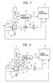
- a laser 1 emits a laser beam 13 having a wavelength of 1064 nm, a pulse width of 10 ns and an output of 100 mJ.
- the laser is a pulsed YAg laser (Yttrium-Aluminum-garnet laser).
- the laser beam 13 is condensed by a condenser lens 2 and enters a gas breakdown chamber 3.
- the laser beam 13 focuses within the breakdown chamber 3 and induces the laser breakdown of the gas in the vicinity of the focal point of the beam.
- the laser beam 13 passes through the breakdown chamber 3 and is absorbed by a beam stopper 12.
- the gaseous sample to be ionized by the laser beam is introduced to the breakdown chamber 3 through a sample passage 4 and discharged.
- the constituent atoms of the gaseous sample that are converted into a plasma by the laser breakdown and ionized in the breakdown chamber 3 are accelerated by an accelerating electrode 5 through a slit in the breakdown chamber.
- the ions pass through slit 5 and are introduced to an ion deflector 6 of a time-of-flight mass spectrometer (hereinafter referred to as "TOF").
- TOF time-of-flight mass spectrometer
- An ion current 11 from the ion collector 7 is processed to obtain the time-of-flight mass spectrum (hereinafter referred to as "TOF spectrum") on the basis of the time at which the ion deflector 6 has been actuated.
- a pulse generator 8 generates a control signal 10 for actuating laser 1, the ion deflector 6 and the signal processor 9 synchronously with each other.
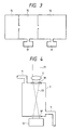
- FIG 2 another embodiment of the present invention is shown.
- This second embodiment of the invention differs from the first in that a signal delay controller 31, a voltage applier 32 and an ion take-out electrode 33 are provided.
- the signal delay controller 31 actuates the voltage applier 32 at a preset time after the time at which a pulse signal is generated so as to apply a voltage to the ion take-out electrode 33. Then, it is accelerated by the accelerating electrode 5 and introduced to the ion deflector 6 of the TOF.
- the plasma emission is spectrometrically measured by a device 81.
- the output of the measurement device 81 is input to the signal processor 9, and it is determined whether or not the intensity of the atom emission lines or the monovalent ion emission lines exceed a preset value. When the preset value is exceeded, then the low valent ions including the monovalent ions are extracted for spectrometric analysis.
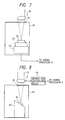
- Figure 3 shows a preferred chamber system for containing the plasma and taking out the ions.
- the sample is contained in ionizing portion 14, which is a breakdown chamber maintained at atmospheric pressure.
- a differential evacuating portion 15 houses the accelerating electrode 5, for example, and is evacuated to a pressure of 10 ⁇ 1 Pa by a turbo molecular pump 17.
- a further chamber 16 houses the mass spectrometer, for example, and is evacuated to 10 ⁇ 3 Pa by another turbo molecular pump 17. Therefore, with this preferred arrangement, the ions generated under atmospheric pressure are introduced into the high vacuum chambers.
- the breakdown chamber 3 shown in the embodiments of the invention in Figures 1 and 2, is able to contain gaseous, liquid and solid samples. Breakdown chamber 3 is shown in greater detail in Figure 4. A gaseous sample is introduced into the breakdown chamber 3 through the sample passage 4.
- the laser beam 13 is condensed by a condenser lens 2, radiated into the breakdown chamber through an aperture 18 disposed at the top of the chamber, and is absorbed by a beam stopper 12 disposed outside of the chamber after passing through an aperture 18′.
- the power density of the laser beam is adjusted to exceed the breakdown threshold value of the sample in the vicinity of the focal point, and therefore the gaseous sample is ionized by the laser breakdown, or when the sample is a particulate substance suspended in a gas only the particulate substance is broken down and the gas medium is not ionized. For example, if the power density of the laser beam is set at a value of not less than 1012 W/cm2, the gaseous sample is broken down and ionized. If the power beam density is set at a value of 1010 to 1011 W/cm2, only the particulate substance in the gas is broken down.
- the power density of the laser beam is set at a value of 1011 to 1012 W/cm2, only the particulate or liquid substance suspended in the gas is broken down, thereby enabling the analysis of a substance in the form of a droplet.
- a breakdown chamber 20 When a liquid sample is to be analyzed, preferably a breakdown chamber 20, as shown in Figure 5, is used.
- the breakdown chamber 20 is of a conical shape, and the liquid is introduced into the chamber through a sample pipe 19.
- the top surface of the conical breakdown chamber 20 has an aperture 21, and the lower portion of the breakdown chamber 20 is narrowed to form a narrow hole 27.
- the liquid sample is discharged from a sample discharge pipe 22 in the form of a very fine stream through the narrow hole.
- the laser beam 13 is condensed by the condenser lens 2 and is introduced to the breakdown chamber 20 through aperture 21.
- the laser beam is condensed along the inner wall surface of the conical breakdown chamber 20 and focuses at the point at which the laser beam passes through the narrow hole to outside of the breakdown chamber 20.
- the laser beam focuses midway of the narrow stream just inside the narrow hole 27 at the lower portion of the chamber, thereby inducing a breakdown of the sample.
- the liquid sample is ionized in air by laser breakdown.
- the power density of the laser beam at the focal point is set at value of not less than 1011 W/cm2
- the liquid sample can be broken down and ionized, thereby enabling the analysis of the liquid for elemental constituents.
- the power density of the laser beam at the focal point is set at 1010 W/cm2, only the particulate substance in the liquid will be broken down and ionized, thereby enabling an analysis of a particulate substance suspended in the liquid.
- the laser beam is focused on a portion of a narrow stream of the liquid that has emerged from narrow hole 27 at the lower portion of the breakdown chamber 20.
- the liquid sample may be broken down by focusing the laser beam on a droplet of the liquid sample that has emerged from the narrow hole 27 at the lower portion of the chamber. It is also possible to break down the liquid by radiating the laser beam in the horizontal direction such that it focuses on the narrow stream or on a droplet of the liquid sample at a predetermined location within the chamber.
- a breakdown chamber 26 is preferably used, as shown in Figure 6.
- the laser beam 13 is condensed by the condenser lens 2 and a focal lens 25 is provided in an upper portion of the break down chamber 26.
- the solid sample 24 is fixed on a sample table 23 disposed in a lower portion of the breakdown chamber 26.
- the power density of the laser beam is adjusted to be 109 to 1011 W/cm2, and a plasma is formed.
- FIG. 7 Another embodiment of a breakdown chamber for a solid sample is shown in Figure 7.
- a sample table driving and controlling device 44 is provided to enable the laser beam to be irradiated onto a given portion of a sample 24 by moving the sample table 23.
- a driving and controlling device 44 is shown for moving the condenser lens 2 to thereby control the position and the direction of the laser beam. In this way, scanning of the sample with the laser beam in the breakdown chamber can be performed.
- FIG. 9 another embodiment of the present invention is shown that includes a driving and controlling device 46 for moving a condenser lens system 43 to enable positioning of the laser beam and to enable scanning irradiation of the object being analyzed.
- a signal relating to the position of the sample table and an output from the respectively disclosed driving and controlling device are supplied to signal processor 9, shown in Figures 1 and 2.
- the signal processor 9 calculates and stores the position of the laser beam on the sample surface, according to the movement of the sample table 23 by driving and controlling device 44; the condenser lens 22 by driving and controlling device 45; and the con denser lens system 43 by driving and controlling device 46, respectively.
- Figure 10 shows an example of a time-of-flight mass spectrometer.
- the ions generated by the breakdown are taken out by an ion take-out electrode 52 disposed in an ion flight tube 51.
- the ions enter the ion flight tube 51 through the entrance 51a provided at one end of the tube 51.
- the direction of progress of the ions is deviated by a minute angle influenced by an ion deflector 53 so that the path of flight of the ions is separated from the path of flight of the neutral atoms.
- the number of ions are measured by an ion detector 54.
- the time required for the ions to reach the ion detector 54 after passing the ion take-out electrode 52 differs in proportion to the mass of the ions.
- the mass of the ions is determined from the time difference of the detection signal of the ion detector 54 and to obtain the number of ions from the intensity of the detecting signal.
- a neutral atom is not influenced by the ion defector 53 and enters an atom detector 55.
- the total number of atoms is obtained from the detection signal of the atom detector 55.
- the ion flight tube is evacuated to a low pressure by molecular turbo pumps 56 and 57.
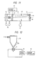
- Figure 11 shows another example of a time-of-flight mass spectrometer, wherein the ion flight tube 51 is further provided with the electrodes 61, 63 and 64, as well as electrodes 52 and 53.
- a voltage controller 62 is provided for the electrode 61.
- the ions taken out of the breakdown chamber pass through electrode 52 and are deflected by an ion deflector 53, as in the TOF shown in Figure 10.
- the ions pass through the midportion of the tube 51 and are influenced by an electrode 63. Then, the ions are repelled by electrode 64 and are reversed in direction. Traveling in the reversed direction through the midportion of the tube, the ions are again deflected by electrode 63.
- voltage controller 62 changes the potential of the electrode 61 whereupon the ions reverse direction again.
- the ions having been twice reversed in direction, now proceed to the ion detector 54, which measures the ion current so as to obtain the number of ions.
- This system is advantageous in that the distance of flight of the ions is lengthened, and the time difference in flight between the different ions increases so that resolution of the mass is enhanced, and it is possible to make the ion flight to smaller in length.
- Figure 12 shows another embodiment of a breakdown chamber and method of breaking down and ionizing a liquid.
- a liquid sample is contained in a liquid container 70 that is funnel-shaped and provided with a small hole 70a formed at the time of the funnel.
- the liquid sample emerges from liquid container 70 through the small hole 70a at the lower portion of the container in the form of a fine line or a droplet.
- the fine line or droplet passes through a gap provided between a pair of opposing electrodes 71.
- a power source 72 is actuated in accordance with a control signal derived from a voltage application controller 73 that applies a high voltage to the electrodes 71 in a pulse-like manner.
- the voltage applied to the electrodes 21 is set at a value above the dielectric breakdown threshold voltage (about 106 V/cm).
- Figure 14 shows a TOF spectrum of a particulate substance in a gas measured in accordance with an embodiment of the present invention wherein the particulate substance was ionized by a laser beam.
- the peaks of Si having a mass of 28, and O having a mass of 16 are mainly detected and it is observed that the main constituent of the particulate substance is SiO x .
- the peak having a mass of 44 is identified to be the peak of SiO ⁇ and the peak having a mass of 60 is identified to be the peak of SiO2 ⁇ .
- the present invention it is possible to ionize and analyze a sample in any form or state, such as a gaseous state, liquid state or solid state. Further, it is possible to selectively ionize and analyze a particulate substance suspended in a gas or a liquid.
- the sample can be of various types, such as an insulator, semi-conductor and conductor, as well as a metal or an oxide. Even a substance having a high ionization potential is able to be broken by the apparatus of the invention for analysis.
- the apparatus of the invention generates monovalent or low valent ions with efficiency by breakdown, thereby enabling analysis of the substance with high sensitivity. Therefore, even trace element constituents of a substance suspended in a gas or liquid can be analyzed.
- the present invention it is possible to analyze a substance for elements or molecules by varying the power density of the laser beam used in irradiating the sample. Furthermore, the element constituent analysis is enabled with high sensitivity by an efficiently size apparatus that combines laser breakdown of the sample with time-of-flight mass spectrometry.
Landscapes
- Physics & Mathematics (AREA)
- Optics & Photonics (AREA)
- Engineering & Computer Science (AREA)
- Plasma & Fusion (AREA)
- Chemical & Material Sciences (AREA)
- Analytical Chemistry (AREA)
- Other Investigation Or Analysis Of Materials By Electrical Means (AREA)
- Electron Tubes For Measurement (AREA)
Applications Claiming Priority (2)
| Application Number | Priority Date | Filing Date | Title |
|---|---|---|---|
| JP1242195A JP2564404B2 (ja) | 1989-09-20 | 1989-09-20 | 質量分析方法 |
| JP242195/89 | 1989-09-20 |
Publications (3)
| Publication Number | Publication Date |
|---|---|
| EP0418785A2 true EP0418785A2 (fr) | 1991-03-27 |
| EP0418785A3 EP0418785A3 (en) | 1992-04-22 |
| EP0418785B1 EP0418785B1 (fr) | 1997-07-16 |
Family
ID=17085698
Family Applications (1)
| Application Number | Title | Priority Date | Filing Date |
|---|---|---|---|
| EP90117867A Expired - Lifetime EP0418785B1 (fr) | 1989-09-20 | 1990-09-17 | Méthode et dispositif pour l'analyse par spectrométrie de masse |
Country Status (5)
| Country | Link |
|---|---|
| US (1) | US5164592A (fr) |
| EP (1) | EP0418785B1 (fr) |
| JP (1) | JP2564404B2 (fr) |
| CA (1) | CA2025991A1 (fr) |
| DE (1) | DE69031062T2 (fr) |
Cited By (1)
| Publication number | Priority date | Publication date | Assignee | Title |
|---|---|---|---|---|
| WO2001055700A1 (fr) * | 2000-01-25 | 2001-08-02 | Gkss-Forschungszentrum Geesthacht Gmbh | Dispositif pour analyser des elements contenus dans des echantillons de liquides sous forme de gouttelettes |
Families Citing this family (16)
| Publication number | Priority date | Publication date | Assignee | Title |
|---|---|---|---|---|
| US5650616A (en) * | 1992-04-14 | 1997-07-22 | Olympus Optical Co., Ltd. | Apparatus and method for analyzing surface |
| US5631462A (en) * | 1995-01-17 | 1997-05-20 | Lucent Technologies Inc. | Laser-assisted particle analysis |
| JP2953344B2 (ja) * | 1995-04-28 | 1999-09-27 | 株式会社島津製作所 | 液体クロマトグラフ質量分析装置 |
| US6849847B1 (en) | 1998-06-12 | 2005-02-01 | Agilent Technologies, Inc. | Ambient pressure matrix-assisted laser desorption ionization (MALDI) apparatus and method of analysis |
| US6037586A (en) * | 1998-06-18 | 2000-03-14 | Universite Laval | Apparatus and method for separating pulsed ions by mass as said pulsed ions are guided along a course |
| WO2005104181A1 (fr) * | 2004-03-30 | 2005-11-03 | Yamanashi Tlo Co., Ltd. | Procede et dispositif d’ionisation pour analyse de masse |
| JP2007303840A (ja) * | 2006-05-08 | 2007-11-22 | Tokyo Metropolitan Univ | 液滴イオン化法、質量分析法及びそれらの装置 |
| JP2009128070A (ja) * | 2007-11-20 | 2009-06-11 | Tokyo Metropolitan Univ | 微小液滴生成方法及び微小液滴生成装置 |
| JP5680008B2 (ja) | 2012-03-08 | 2015-03-04 | 株式会社東芝 | イオン源、重粒子線照射装置、イオン源の駆動方法、および、重粒子線照射方法 |
| JP2015138667A (ja) * | 2014-01-22 | 2015-07-30 | アルバック・ファイ株式会社 | イオン源、イオン銃、分析装置 |
| US9506871B1 (en) | 2014-05-25 | 2016-11-29 | Kla-Tencor Corporation | Pulsed laser induced plasma light source |
| DE102016113771B4 (de) * | 2016-07-26 | 2019-11-07 | Bundesrepublik Deutschland, Vertreten Durch Den Bundesminister Für Wirtschaft Und Energie, Dieser Vertreten Durch Den Präsidenten Der Bundesanstalt Für Materialforschung Und -Prüfung (Bam) | Analysevorrichtung für gasförmige Proben und Verfahren zum Nachweis von Analyten in einem Gas |
| CN111199862B (zh) * | 2018-11-20 | 2021-04-27 | 中国科学院大连化学物理研究所 | 一种毛细管微区电离源 |
| US10652441B1 (en) * | 2019-05-10 | 2020-05-12 | The Boeing Company | Systems and methods for protecting imaging devices against high-radiant-flux light |
| CA3105312A1 (fr) * | 2020-01-06 | 2021-07-06 | Institut National De La Recherche Scientifique | Systeme optique et methode d`extraction et de raffinage metallurgique |
| CN116990287B (zh) * | 2023-08-14 | 2024-05-03 | 元素聚焦(青岛)科技有限公司 | 一种固体样品光谱-质谱成像系统及方法 |
Family Cites Families (20)
| Publication number | Priority date | Publication date | Assignee | Title |
|---|---|---|---|---|
| FR1580234A (fr) * | 1968-05-15 | 1969-09-05 | ||
| US3673405A (en) * | 1971-01-14 | 1972-06-27 | Bendix Corp | Gas inlet system for a mass spectrometer |
| US3727047A (en) * | 1971-07-22 | 1973-04-10 | Avco Corp | Time of flight mass spectrometer comprising a reflecting means which equalizes time of flight of ions having same mass to charge ratio |
| US3914655A (en) * | 1973-06-28 | 1975-10-21 | Ibm | High brightness ion source |
| US3953732A (en) * | 1973-09-28 | 1976-04-27 | The University Of Rochester | Dynamic mass spectrometer |
| JPS59942B2 (ja) * | 1974-01-11 | 1984-01-09 | 株式会社日立製作所 | ホウデンガタイオンゲンヨウデンゲン |
| DE2837715A1 (de) * | 1978-08-30 | 1980-03-13 | Leybold Heraeus Gmbh & Co Kg | Verfahren zur analyse organischer substanzen |
| DE2942386C2 (de) * | 1979-10-19 | 1984-01-12 | Ulrich Dr. 8000 München Boesl | Ionenquelle |
| JPS5717855A (en) * | 1980-07-02 | 1982-01-29 | Leybold Heraeus Gmbh & Co Kg | Organic material analyzing method and apparatus |
| JPS5753653A (en) * | 1980-09-17 | 1982-03-30 | Jeol Ltd | Liquid chromatography mass spectrometer |
| US4383171A (en) * | 1980-11-17 | 1983-05-10 | The United States Of America As Represented By The Administrator Of The National Aeronautics And Space Administration | Particle analyzing method and apparatus |
| JPS58157043A (ja) * | 1982-03-15 | 1983-09-19 | Nippon Telegr & Teleph Corp <Ntt> | イオンビ−ム発生装置 |
| US4634864A (en) * | 1983-10-27 | 1987-01-06 | Atom Sciences, Inc. | Ultrasensitive method for measuring isotope abundance ratios |
| US4733073A (en) * | 1983-12-23 | 1988-03-22 | Sri International | Method and apparatus for surface diagnostics |
| JPS6226757A (ja) * | 1985-07-25 | 1987-02-04 | Shimadzu Corp | 誘導結合プラズマ質量分析装置 |
| US4849628A (en) * | 1987-05-29 | 1989-07-18 | Martin Marietta Energy Systems, Inc. | Atmospheric sampling glow discharge ionization source |
| GB2211020A (en) * | 1987-10-10 | 1989-06-21 | Wallach Eric Robert | Microprobe mass analyser |
| US4818862A (en) * | 1987-10-21 | 1989-04-04 | Iowa State University Research Foundation, Inc. | Characterization of compounds by time-of-flight measurement utilizing random fast ions |
| US4920264A (en) * | 1989-01-17 | 1990-04-24 | Sri International | Method for preparing samples for mass analysis by desorption from a frozen solution |
| DE3904308A1 (de) * | 1989-02-14 | 1990-08-16 | Strahlen Umweltforsch Gmbh | Verfahren zur einzelteilchen-zaehlung bei der flugzeit-massenspektrometrie |
-
1989
- 1989-09-20 JP JP1242195A patent/JP2564404B2/ja not_active Expired - Lifetime
-
1990
- 1990-09-13 US US07/581,908 patent/US5164592A/en not_active Expired - Lifetime
- 1990-09-17 EP EP90117867A patent/EP0418785B1/fr not_active Expired - Lifetime
- 1990-09-17 DE DE69031062T patent/DE69031062T2/de not_active Expired - Fee Related
- 1990-09-20 CA CA002025991A patent/CA2025991A1/fr not_active Abandoned
Cited By (1)
| Publication number | Priority date | Publication date | Assignee | Title |
|---|---|---|---|---|
| WO2001055700A1 (fr) * | 2000-01-25 | 2001-08-02 | Gkss-Forschungszentrum Geesthacht Gmbh | Dispositif pour analyser des elements contenus dans des echantillons de liquides sous forme de gouttelettes |
Also Published As
| Publication number | Publication date |
|---|---|
| EP0418785A3 (en) | 1992-04-22 |
| US5164592A (en) | 1992-11-17 |
| JP2564404B2 (ja) | 1996-12-18 |
| DE69031062T2 (de) | 1998-02-19 |
| EP0418785B1 (fr) | 1997-07-16 |
| CA2025991A1 (fr) | 1991-03-21 |
| DE69031062D1 (de) | 1997-08-21 |
| JPH03105841A (ja) | 1991-05-02 |
Similar Documents
| Publication | Publication Date | Title |
|---|---|---|
| EP0418785B1 (fr) | Méthode et dispositif pour l'analyse par spectrométrie de masse | |
| US4733073A (en) | Method and apparatus for surface diagnostics | |
| US7649170B2 (en) | Dual-polarity mass spectrometer | |
| US8101923B2 (en) | System and method for spatially-resolved chemical analysis using microplasma desorption and ionization of a sample | |
| EP1060380B1 (fr) | Analyseur de particules atmospheriques | |
| Doria et al. | A study of the parameters of particles ejected from a laser plasma | |
| JP3676298B2 (ja) | 化学物質の検出装置および化学物質の検出方法 | |
| EP0744617A2 (fr) | Procédé et appareil pour l'analyse de surface | |
| US7671330B2 (en) | High resolution mass spectrometry method and system for analysis of whole proteins and other large molecules | |
| EP0452767B1 (fr) | Spectromètre de masse pour atomes neutres, pulvérisés cathodiquement et ionisés par laser | |
| Wolf et al. | Ion-recoil momentum spectroscopy in a laser-cooled atomic sample | |
| Hattendorf et al. | Laser Ablation Inductively Coupled Plasma Mass Spectrometry | |
| Tabrizchi et al. | Design, construction and calibration of a laser ionization time-of-flight mass spectrometer | |
| EP0167561B1 (fr) | Procede et dispositif de diagnostic de surface | |
| CN112074927A (zh) | 用于粒子的质谱分析的装置和方法 | |
| JP3384063B2 (ja) | 質量分析方法および質量分析装置 | |
| Falk | Methods for the detection of single atoms using optical and mass spectrometry. Invited lecture | |
| Apollonov | Multi charged ions and mass spectrometry | |
| JPH03291559A (ja) | レーザイオン化中性粒子質量分析装置 | |
| JP2001215216A (ja) | 顕微レーザ質量分析計 | |
| JP2610035B2 (ja) | 表面分析装置 | |
| Chen | Construction and characterization of an inductively coupled plasma time-of-flight mass spectrometer | |
| Fan | Particle analysis in infrared laser desorption and ablation | |
| JP2000323088A (ja) | 反射型飛行時間質量分析装置および分析方法 | |
| NL8420306A (nl) | Werkwijze en inrichting voor oppervlakte-diagnose. |
Legal Events
| Date | Code | Title | Description |
|---|---|---|---|
| PUAI | Public reference made under article 153(3) epc to a published international application that has entered the european phase |
Free format text: ORIGINAL CODE: 0009012 |
|
| 17P | Request for examination filed |
Effective date: 19901220 |
|
| AK | Designated contracting states |
Kind code of ref document: A2 Designated state(s): DE FR GB |
|
| PUAL | Search report despatched |
Free format text: ORIGINAL CODE: 0009013 |
|
| AK | Designated contracting states |
Kind code of ref document: A3 Designated state(s): DE FR GB |
|
| 17Q | First examination report despatched |
Effective date: 19950209 |
|
| GRAG | Despatch of communication of intention to grant |
Free format text: ORIGINAL CODE: EPIDOS AGRA |
|
| GRAH | Despatch of communication of intention to grant a patent |
Free format text: ORIGINAL CODE: EPIDOS IGRA |
|
| GRAH | Despatch of communication of intention to grant a patent |
Free format text: ORIGINAL CODE: EPIDOS IGRA |
|
| GRAA | (expected) grant |
Free format text: ORIGINAL CODE: 0009210 |
|
| AK | Designated contracting states |
Kind code of ref document: B1 Designated state(s): DE FR GB |
|
| REF | Corresponds to: |
Ref document number: 69031062 Country of ref document: DE Date of ref document: 19970821 |
|
| ET | Fr: translation filed | ||
| PLBE | No opposition filed within time limit |
Free format text: ORIGINAL CODE: 0009261 |
|
| STAA | Information on the status of an ep patent application or granted ep patent |
Free format text: STATUS: NO OPPOSITION FILED WITHIN TIME LIMIT |
|
| 26N | No opposition filed | ||
| REG | Reference to a national code |
Ref country code: GB Ref legal event code: IF02 |
|
| PGFP | Annual fee paid to national office [announced via postgrant information from national office to epo] |
Ref country code: FR Payment date: 20060814 Year of fee payment: 17 |
|
| PGFP | Annual fee paid to national office [announced via postgrant information from national office to epo] |
Ref country code: GB Payment date: 20060816 Year of fee payment: 17 |
|
| PGFP | Annual fee paid to national office [announced via postgrant information from national office to epo] |
Ref country code: DE Payment date: 20060828 Year of fee payment: 17 |
|
| GBPC | Gb: european patent ceased through non-payment of renewal fee |
Effective date: 20070917 |
|
| PG25 | Lapsed in a contracting state [announced via postgrant information from national office to epo] |
Ref country code: DE Free format text: LAPSE BECAUSE OF NON-PAYMENT OF DUE FEES Effective date: 20080401 |
|
| REG | Reference to a national code |
Ref country code: FR Ref legal event code: ST Effective date: 20080531 |
|
| PG25 | Lapsed in a contracting state [announced via postgrant information from national office to epo] |
Ref country code: FR Free format text: LAPSE BECAUSE OF NON-PAYMENT OF DUE FEES Effective date: 20071001 |
|
| PG25 | Lapsed in a contracting state [announced via postgrant information from national office to epo] |
Ref country code: GB Free format text: LAPSE BECAUSE OF NON-PAYMENT OF DUE FEES Effective date: 20070917 |