EP0419262A2 - Anneau anti-implosion d'un tube à rayons cathodiques - Google Patents
Anneau anti-implosion d'un tube à rayons cathodiques Download PDFInfo
- Publication number
- EP0419262A2 EP0419262A2 EP90310307A EP90310307A EP0419262A2 EP 0419262 A2 EP0419262 A2 EP 0419262A2 EP 90310307 A EP90310307 A EP 90310307A EP 90310307 A EP90310307 A EP 90310307A EP 0419262 A2 EP0419262 A2 EP 0419262A2
- Authority
- EP
- European Patent Office
- Prior art keywords
- tension band
- band
- ray tube
- cathode ray
- tension
- Prior art date
- Legal status (The legal status is an assumption and is not a legal conclusion. Google has not performed a legal analysis and makes no representation as to the accuracy of the status listed.)
- Granted
Links
Images


Classifications
-
- H—ELECTRICITY
- H01—ELECTRIC ELEMENTS
- H01J—ELECTRIC DISCHARGE TUBES OR DISCHARGE LAMPS
- H01J29/00—Details of cathode-ray tubes or of electron-beam tubes of the types covered by group H01J31/00
- H01J29/86—Vessels; Containers; Vacuum locks
- H01J29/87—Arrangements for preventing or limiting effects of implosion of vessels or containers
-
- H—ELECTRICITY
- H04—ELECTRIC COMMUNICATION TECHNIQUE
- H04N—PICTORIAL COMMUNICATION, e.g. TELEVISION
- H04N5/00—Details of television systems
- H04N5/64—Constructional details of receivers, e.g. cabinets or dust covers
- H04N5/645—Mounting of picture tube on chassis or in housing
Definitions
- the present invention relates to implosion-prevention band and cathode ray tube fastened therewith, and in particular, to a tension band wherein the materials and the structure are improved.
- a tension band for a cathode ray tube is placed tightly around the skirt of a facepanel of the cathode ray tube to prevent implosion of the cathode ray tube by restraining the expansion of cracks in the facepanel when strong pressure or shock is exerted on the facepanel, causing the cathode ray tube to implode, due to a high-vacuum in the cathode ray tube.
- a conventional tension band 10 is made of a metal having a high tensile force, and apertured mounting lugs 20 are fixed to the corners of the tension band by welding.
- the tension band 10 is placed tightly around both the skirt of the facepanel 30, i.e., banding portion 32, and the mold match line between the facepanel 30 and a funnel 40, and drawn up to a very high tension.
- an adhesive tape 50 made of heat-resist material is interposed between the tension band 10 and banding portion 32, so that the tension band 10 is affixed to the skirt of the facepanel 30, while being spaced apart from the banding portion 32.
- the adhesive tape 50 is employed to prevent the banding portion 32 from directly contacting with the tension band 10 which is subjected to heat, since the banding portion is susceptible to heat.
- the tension band 10 is affixed to the cathode ray tube, even if the cathode ray tube is undergoing implosion, the metallic tension band, whose surface is smooth, is securely fastened to the predetermined portion of the cathode ray tube by the use of the adhesive tape 50, and does not separate from the banding portion 32.
- the tension band 10 is adapted to minimize the implosion-induced violent scattering of the facepanel.
- the tension band is made of metal having high tensile force and the adhesive tape for insulating is used, with the obvious consequence of a high manufacturing cost.
- intense heat energy is required for thermal expansion of the metallic tension band, and deterioration of the tension band quality can occur, resulting in weakening of the tensile force, due to the direct heating by flame.
- An arrangement of precise welding devices is necessary to install the mounting lug, which is made by a separate manufacturing process, at each corner of the tension band.
- another separate welding device is needed to prepare the tension band in a loop shape.
- the present invention is intended to obviate these and other problems of the conventional system.
- the invention provides a tension band which comprises a single band unit having no seam therein and is made of synthetic resin containing polyamide and glass fiber.
- an adhesive means is applied to the inner side of the tension band.
- a cathode ray tube fastened with a tension band which comprises a single band unit having no seam and is made of synthetic resin containing polyamide and glass fiber.
- FIG 3 illustrates a cathode ray tube fastened with a tension band according to an embodiment of the present invention, of which section A′ is illustrated in enlargement in Figure 4.
- the tension band 100 is placed tightly around the skirt of a facepanel, i.e., banding portion 32 under very high tensile strength.
- the tension band 100 may be made by injection molding of a kind of engineering plastics material generally containing about 70 to 30 percent polyamide and about 30 to 70 percent glass fiber, and is integrally formed with mounting lug 200 at each corner thereof. Alternatively, however, the tension band and the mounting lugs can be separately formed and combined with each other.
- the length of the glass fiber may be about 3 to 12 mm and the diameter of which is preferably 6 to 13 ⁇ m.
- This type of tension band 100 may be manufactured by injection molding under high pressure, thereby having much higher tensile force than the 650kg/cm2 which is the requisite tensile force in a tension band of a cathode ray tube, and having an elastic recovery rate of within 5%.
- the ratio of the inner circumferential length of the tension band 100 against the outer circumferential length of the surface of the banding portion is set in the range of about 99.79 to 99.13% where the glass fibre content ratio is 30%, about 99.13 to 99.51% where it is 50%, and about 99.51 to 99.90% where it is 60%, respectively.
- An adhesive 110 such as, for example, ordinary adhesive or epoxy resin or the like, which is apt to melt on heating, is applied to the inner side of the tension band, contacting a banding portion 32, so as to prevent the tension band 100 from sliding on the banding portion.
- the adhesive 110 melted in solvent is applied in fluid-state to the inner side of the tension band 100, and then solidified. It is preferable that the adhesive becomes sticky upon being subjected to heat of about 150 to 200°C.
- An adhesive band made of the same material as the adhesive, may be attached instead of applying the adhesive.
- conductive substances such as graphite or ferrite can be added to the materials of the tension band, so that static electricity on the surface of the screen of the cathode ray tube may be effectively lowered through electrical connection of the tension band with conductive film coated on the surface of the screen.
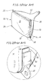
- a tension band according to a further embodiment of the present invention as illustrated in Figure 5 can be combined with a metallic or non-metallic mounting lug 210, separately formed from the tension band, at each corner thereof.
- a separately formed mounting lug may be incorporated with the tension band during the process of injection molding of the tension band. Because of the thermoplastic property of the band material, to put the tension band around the cathode ray tube an indirect heating method using hot air, or a heating medium such as hot oil, can be used instead of direct heating by flame, until the thermal expansion of the tension band is sufficiently effected under the temperature level of about 150 to 200°C , whereby the tension band is tightly fastened around the cathode ray tube without any damage or deformation of the tension band.
- the heating temperature should be kept in the aforesaid range, because a heavy load should be applied to fasten the tension band if the heating temperature is equal to or below 150°C and, on the contrary, the deformation of the material occurs if the temperature is above 200°C.
- a heating method by ultrasonic can be adapted for heating the tension band according to the present invention.
- the inventors have confirmed that static electricity travelling on the screen can be passed through the tension land to the ground, due to the low surface resistance of the non-conductive tension band.
- the tension band according to the present invention is relatively soft and its thermal conductivity is lower than that of the metallic band, so that the conventional adhesive tape is not essential.
- the mounting lug can be integrally molded with the tension band, the separate manufacturing process or welding process for the mounting lug, which were necessary in the prior art, are not necessary.
- the thermal energy required to mount the tension band is much reduced compared with the known metallic tension band, thereby bringing about an energy saving and thus resulting in a reduction in manufacturing cost.
- the tension band after being mounted on the cathode ray tube, has more stable tensile force than any other conventional implosion-prevention bands, which partially results from the use of indirect heating by hot air or ultrasonic heating, as opposed to the conventional direct heating by a flame, so that the local damage of the material ty thermal impact does not occur.
- the tension band according to the present invention is securely affixed to the banding portion of the cathode ray tube and, consequently, the tension band effectively prevents crack expansion and restrains violent inward scattering of the cathode ray tube induced by implosion thereof.
Landscapes
- Engineering & Computer Science (AREA)
- Multimedia (AREA)
- Signal Processing (AREA)
- Vessels, Lead-In Wires, Accessory Apparatuses For Cathode-Ray Tubes (AREA)
Applications Claiming Priority (4)
| Application Number | Priority Date | Filing Date | Title |
|---|---|---|---|
| KR2019890013714U KR920001585Y1 (ko) | 1989-09-20 | 1989-09-20 | 음극선관용 방폭밴드 |
| KR1371489 | 1989-09-20 | ||
| KR816590 | 1990-06-02 | ||
| KR1019900008165A KR920010725B1 (ko) | 1990-06-02 | 1990-06-02 | 방폭밴드와 이를 채용한 음극선관 |
Publications (3)
| Publication Number | Publication Date |
|---|---|
| EP0419262A2 true EP0419262A2 (fr) | 1991-03-27 |
| EP0419262A3 EP0419262A3 (en) | 1991-10-30 |
| EP0419262B1 EP0419262B1 (fr) | 1996-03-13 |
Family
ID=26628090
Family Applications (1)
| Application Number | Title | Priority Date | Filing Date |
|---|---|---|---|
| EP90310307A Expired - Lifetime EP0419262B1 (fr) | 1989-09-20 | 1990-09-20 | Anneau anti-implosion d'un tube à rayons cathodiques |
Country Status (5)
| Country | Link |
|---|---|
| US (1) | US5313284A (fr) |
| EP (1) | EP0419262B1 (fr) |
| JP (1) | JPH0770293B2 (fr) |
| DE (1) | DE69025836T2 (fr) |
| TW (1) | TW202520B (fr) |
Cited By (1)
| Publication number | Priority date | Publication date | Assignee | Title |
|---|---|---|---|---|
| WO2005055597A1 (fr) * | 2003-12-05 | 2005-06-16 | Thomson Licensing | Tube cathodique comprenant des pattes qui relient le tube a un boitier |
Families Citing this family (1)
| Publication number | Priority date | Publication date | Assignee | Title |
|---|---|---|---|---|
| JPH0743932Y2 (ja) * | 1991-11-29 | 1995-10-09 | 三星電管株式會社 | 防爆バンドを具備した陰極線管 |
Family Cites Families (5)
| Publication number | Priority date | Publication date | Assignee | Title |
|---|---|---|---|---|
| US3647960A (en) * | 1969-01-06 | 1972-03-07 | Hitachi Ltd | Implosion-proof cathode-ray tube and method of making same |
| CA1068205A (fr) * | 1975-03-27 | 1979-12-18 | Yutaka Hori | Stratifie thermocurable |
| US4332329A (en) * | 1977-10-25 | 1982-06-01 | Ppg Industries, Inc. | Implosion coatings |
| JPS57191946A (en) * | 1981-05-21 | 1982-11-25 | Toshiba Corp | Explosion-proof cathode-ray tube |
| JPH0719548B2 (ja) * | 1985-03-08 | 1995-03-06 | ソニー株式会社 | 陰極線管の製造方法 |
-
1990
- 1990-09-12 TW TW079107655A patent/TW202520B/zh active
- 1990-09-20 US US07/585,788 patent/US5313284A/en not_active Expired - Fee Related
- 1990-09-20 JP JP2254051A patent/JPH0770293B2/ja not_active Expired - Fee Related
- 1990-09-20 EP EP90310307A patent/EP0419262B1/fr not_active Expired - Lifetime
- 1990-09-20 DE DE69025836T patent/DE69025836T2/de not_active Expired - Lifetime
Cited By (1)
| Publication number | Priority date | Publication date | Assignee | Title |
|---|---|---|---|---|
| WO2005055597A1 (fr) * | 2003-12-05 | 2005-06-16 | Thomson Licensing | Tube cathodique comprenant des pattes qui relient le tube a un boitier |
Also Published As
| Publication number | Publication date |
|---|---|
| DE69025836T2 (de) | 1996-09-19 |
| US5313284A (en) | 1994-05-17 |
| EP0419262B1 (fr) | 1996-03-13 |
| EP0419262A3 (en) | 1991-10-30 |
| JPH0770293B2 (ja) | 1995-07-31 |
| TW202520B (fr) | 1993-03-21 |
| JPH03133033A (ja) | 1991-06-06 |
| DE69025836D1 (de) | 1996-04-18 |
Similar Documents
| Publication | Publication Date | Title |
|---|---|---|
| EP0720946A1 (fr) | Dispositif auto-adhésif de protection contre le givre | |
| EP0556290B1 (fr) | Enrobage d'un substrat a l'aide d'un article thermoreformable | |
| EP0419262B1 (fr) | Anneau anti-implosion d'un tube à rayons cathodiques | |
| US5639552A (en) | Stong flexible pre-impregnation of fiber reinforced thermoplastic resin free from a void in matrix | |
| KR880002578B1 (ko) | 말단 권선도체의 고착방법 및 장치 | |
| CA2808279C (fr) | Isolateur entierement composite pour coupe-circuit electrique | |
| EP0137952B1 (fr) | Plaque isolante pour joint isolé de rails | |
| CN1027942C (zh) | 张力带和用这种张力带系牢的阴极射线管 | |
| KR940005605Y1 (ko) | 칼라브라운관의 편향요크 유동 방지 장치 | |
| JP2006104298A (ja) | 防爆用粘着テープ、その製造方法、ブラウン管の防爆方法並びにブラウン管 | |
| US3350154A (en) | Reinforced cathode-ray tube and face plate therefor | |
| US5145434A (en) | Video display device and method of mounting a cathode ray tube in a cabinet of a video display device | |
| WO1993026015A1 (fr) | Cloche d'isolateur | |
| JP2584655B2 (ja) | ブラウン管用防爆テープ及びブラウン管の静電気除去回路を形成する方法 | |
| US4152187A (en) | Method of sealing a vacuum induction furnace | |
| KR0131393B1 (ko) | 텔레비젼 브라운관의 금속밴드 설치 방법 | |
| US3647960A (en) | Implosion-proof cathode-ray tube and method of making same | |
| CN220628866U (zh) | 一种内置螺纹型钢钉的热缩保护套管 | |
| CN222883865U (zh) | 一种防止带胶套管脱落结构 | |
| CN216069091U (zh) | 散热泡棉 | |
| KR0149456B1 (ko) | 음극선관용 패널 | |
| US5249059A (en) | Cathode-ray tube having explosion proof band | |
| AU640380B2 (en) | Environmental sealing | |
| PL66892B1 (fr) | ||
| KR910006390B1 (ko) | 인슈레이숀 점착테이프 |
Legal Events
| Date | Code | Title | Description |
|---|---|---|---|
| PUAI | Public reference made under article 153(3) epc to a published international application that has entered the european phase |
Free format text: ORIGINAL CODE: 0009012 |
|
| AK | Designated contracting states |
Kind code of ref document: A2 Designated state(s): DE FR GB NL |
|
| PUAL | Search report despatched |
Free format text: ORIGINAL CODE: 0009013 |
|
| AK | Designated contracting states |
Kind code of ref document: A3 Designated state(s): DE FR GB NL |
|
| 17P | Request for examination filed |
Effective date: 19920421 |
|
| RAP1 | Party data changed (applicant data changed or rights of an application transferred) |
Owner name: SAMSUNG DISPLAY DEVICES CO., LTD. |
|
| 17Q | First examination report despatched |
Effective date: 19950504 |
|
| GRAA | (expected) grant |
Free format text: ORIGINAL CODE: 0009210 |
|
| AK | Designated contracting states |
Kind code of ref document: B1 Designated state(s): DE FR GB NL |
|
| REF | Corresponds to: |
Ref document number: 69025836 Country of ref document: DE Date of ref document: 19960418 |
|
| ET | Fr: translation filed | ||
| PLBE | No opposition filed within time limit |
Free format text: ORIGINAL CODE: 0009261 |
|
| STAA | Information on the status of an ep patent application or granted ep patent |
Free format text: STATUS: NO OPPOSITION FILED WITHIN TIME LIMIT |
|
| 26N | No opposition filed | ||
| REG | Reference to a national code |
Ref country code: GB Ref legal event code: IF02 |
|
| PGFP | Annual fee paid to national office [announced via postgrant information from national office to epo] |
Ref country code: FR Payment date: 20020910 Year of fee payment: 13 |
|
| PGFP | Annual fee paid to national office [announced via postgrant information from national office to epo] |
Ref country code: GB Payment date: 20020918 Year of fee payment: 13 |
|
| PGFP | Annual fee paid to national office [announced via postgrant information from national office to epo] |
Ref country code: NL Payment date: 20020930 Year of fee payment: 13 |
|
| PG25 | Lapsed in a contracting state [announced via postgrant information from national office to epo] |
Ref country code: GB Free format text: LAPSE BECAUSE OF NON-PAYMENT OF DUE FEES Effective date: 20030920 |
|
| PG25 | Lapsed in a contracting state [announced via postgrant information from national office to epo] |
Ref country code: NL Free format text: LAPSE BECAUSE OF NON-PAYMENT OF DUE FEES Effective date: 20040401 |
|
| GBPC | Gb: european patent ceased through non-payment of renewal fee |
Effective date: 20030920 |
|
| PG25 | Lapsed in a contracting state [announced via postgrant information from national office to epo] |
Ref country code: FR Free format text: LAPSE BECAUSE OF NON-PAYMENT OF DUE FEES Effective date: 20040528 |
|
| NLV4 | Nl: lapsed or anulled due to non-payment of the annual fee |
Effective date: 20040401 |
|
| REG | Reference to a national code |
Ref country code: FR Ref legal event code: ST |
|
| PGFP | Annual fee paid to national office [announced via postgrant information from national office to epo] |
Ref country code: DE Payment date: 20090917 Year of fee payment: 20 |
|
| PG25 | Lapsed in a contracting state [announced via postgrant information from national office to epo] |
Ref country code: DE Free format text: LAPSE BECAUSE OF EXPIRATION OF PROTECTION Effective date: 20100920 |