EP0419696A1 - Abhitzekessel mit Zwischenüberhitzer - Google Patents
Abhitzekessel mit Zwischenüberhitzer Download PDFInfo
- Publication number
- EP0419696A1 EP0419696A1 EP89117784A EP89117784A EP0419696A1 EP 0419696 A1 EP0419696 A1 EP 0419696A1 EP 89117784 A EP89117784 A EP 89117784A EP 89117784 A EP89117784 A EP 89117784A EP 0419696 A1 EP0419696 A1 EP 0419696A1
- Authority
- EP
- European Patent Office
- Prior art keywords
- temperature side
- superheater
- low
- exhaust gas
- reheater
- Prior art date
- Legal status (The legal status is an assumption and is not a legal conclusion. Google has not performed a legal analysis and makes no representation as to the accuracy of the status listed.)
- Granted
Links
- 238000011144 upstream manufacturing Methods 0.000 claims abstract description 11
- 206010037660 Pyrexia Diseases 0.000 claims description 4
- 238000011084 recovery Methods 0.000 abstract description 4
- XLYOFNOQVPJJNP-UHFFFAOYSA-N water Substances O XLYOFNOQVPJJNP-UHFFFAOYSA-N 0.000 description 27
- 239000011295 pitch Substances 0.000 description 10
- 238000005192 partition Methods 0.000 description 6
- 239000012530 fluid Substances 0.000 description 5
- 238000010586 diagram Methods 0.000 description 4
- 239000000203 mixture Substances 0.000 description 4
- 238000002347 injection Methods 0.000 description 3
- 239000007924 injection Substances 0.000 description 3
- 230000001105 regulatory effect Effects 0.000 description 3
- 239000007921 spray Substances 0.000 description 3
- 238000010276 construction Methods 0.000 description 2
- 239000004568 cement Substances 0.000 description 1
- 239000000470 constituent Substances 0.000 description 1
Images

Classifications
-
- F—MECHANICAL ENGINEERING; LIGHTING; HEATING; WEAPONS; BLASTING
- F22—STEAM GENERATION
- F22B—METHODS OF STEAM GENERATION; STEAM BOILERS
- F22B1/00—Methods of steam generation characterised by form of heating method
- F22B1/02—Methods of steam generation characterised by form of heating method by exploitation of the heat content of hot heat carriers
- F22B1/18—Methods of steam generation characterised by form of heating method by exploitation of the heat content of hot heat carriers the heat carrier being a hot gas, e.g. waste gas such as exhaust gas of internal-combustion engines
- F22B1/1807—Methods of steam generation characterised by form of heating method by exploitation of the heat content of hot heat carriers the heat carrier being a hot gas, e.g. waste gas such as exhaust gas of internal-combustion engines using the exhaust gases of combustion engines
- F22B1/1815—Methods of steam generation characterised by form of heating method by exploitation of the heat content of hot heat carriers the heat carrier being a hot gas, e.g. waste gas such as exhaust gas of internal-combustion engines using the exhaust gases of combustion engines using the exhaust gases of gas-turbines
-
- F—MECHANICAL ENGINEERING; LIGHTING; HEATING; WEAPONS; BLASTING
- F22—STEAM GENERATION
- F22G—SUPERHEATING OF STEAM
- F22G7/00—Steam superheaters characterised by location, arrangement, or disposition
- F22G7/14—Steam superheaters characterised by location, arrangement, or disposition in water-tube boilers, e.g. between banks of water tubes
Definitions
- the present invention relates to a reheat type exhaust gas boiler in which superheaters and reheaters are disposed in parallel in the most upstream portion in the direction of an exhaust gas flow within an exhaust gas boiler main body.
- an exhaust gas boiler for recovering heat of exhaust gas discharged from various heat generating sources such as gas turbines, diesel engines, cement calcinators or the like have been well known, for instance, those disclosed in Laid-Open Japanese Patent Specification No. 61-186702 (1986) are known.
- two sets of secondary superheaters 102 and secondary reheaters 103 are disposed in parallel in the most upstream portion in the direction of an exhaust gas flow within an exhaust gas boiler main body 101 through which exhaust gas flows in the horizontal direction as shown in Figs. 3 and 4.
- On the downstream side with respect to gas of the respective secondary superheaters 102 are respectively disposed primary reheaters 104, while on the downstream side with respect to gas of the respective secondary reheaters 103 are respectively disposed primary superheaters 105, and further on the gas downstream side of them is disposed a high-pressure evaporator 106 along the widthwise direction of a flue.
- this high-pressure evaporator 106 On the gas downstream side of this high-pressure evaporator 106 is disposed a high-pressure economizer 107, and on the gas downstream side of this high-pressure economizer 107 are successively disposed a low-pressure superheater 108, a low-pressure evaporator 109 and a low-pressure economizer 110.
- the high-pressure steam drum 111 is connected to an outlet of the high-pressure economizer 107, and also connected to a bottom header 106a of the high-pressure evaporator 106 via a down comer 113.
- a top header 106b of the high-pressure evaporator 106 is connected to the high-pressure steam drum 111 via a riser tube 114.
- a steam section of the high-pressure steam drum 111 is connected to an inlet section of the primary superheater 105 via a steam pipe 115.
- the low-pressure steam drum 112 is connected to an outlet of the low-pressure economizer 110, and also connected to a bottom header 109a of the low- pressure evaporator 109 via a down comer 116.
- a top header 109b of the low pressure evaporator 109 is connected to the low-pressure steam drum 112 via a riser tube 117.
- the low-pressure steam drum 112 is connected to an inlet side of the high-pressure economizer 107 via a feed water pipe 119 provided with a feed water pump 118.
- a steam section of the low-pressure steam drum 112 is connected to an inlet section of the low-pressure superheater 108 via a steam pipe 120.
- the inlet of the primary reheater 104 is communicated with a steam turbine not shown through a pipe for returning steam which has done a work in the steam turbine.
- the outlet the primary reheater 104 is communicated with the secondary reheater 103 through a communication pipe not shown.
- the outlet of the primary superheater 105 is communicated with the secondary superheater 102 through a communication pipe not shown. And, between these superheaters and reheaters disposed in parallel are provided partition walls 121.
- Exhaust gas discharged from a heat generating source flows into the inlet of the exhaust gas boiler main body 101, then during the period when the exhaust gas flow from the side of the secondary superheater 102 and the secondary reheater 103 to the side of the low-pressure economizer 110, heat-exchange is effected with the fluid flowing through the heat transfer tubes in the respective units, and after it has become a low temperature, it flows out through the outlet of the exhaust gas boiler main body 101.
- feed water (condensate) is sent to the low-pressure economizer 110 by means of a condensate pump not shown, and here it is heated by the exhaust gas. Then, the heated feed water is sent from the low-pressure economizer 110 to the low-pressure steam drum 112. A part of the feed water in the low-pressure steam drum 112 is sent to the low-pressure evaporator 109 via the down comer 116, then it is heated in this low-pressure evaporator 109 by the exhaust gas and becomes steam/water mixture fluid, and it is returned through the riser tube 117 to the low-pressure steam drum 112.
- This steam/water mixture fluid returned to the low-pressure steam drum 112 is separated into steam and water, the steam is sent through the steam pipe 120 to the low-pressure superheater 108, in which the steam is superheated.
- the feed water in the low-pressure steam drum 112 passes through the feed water pipe 119, and is boosted in pressure by the pump 118, and after it has become high pressure, it is sent to the high-pressure economizer 107. Then, in this high-pressure economizer 107, the feed water is heated by the exhaust gas and sent to the high-pressure steam drum 111.
- the feed water sent to the high-pressure steam drum 111 is partly sent to the high-pressure evaporator 106 through the down comer 113, here it is heated by the exhaust gas and becomes steam/water mixture fluid, and it is returned through the riser tube 114 to the high-pressure steam drum 111.
- the mixture fluid is separated into steam and feed water, the steam is sent through the steam pipe 115 to the primary superheater 105, and in this primary superheater 105 it is superheated by the exhaust gas. Then the superheated steam is sent to the steam temperature lowerer through the above-described communication pipe, after the steam has been controlled into a predetermined temperature in this temperature lowerer, it is sent to the secondary superheater 102, and in this secondary superheater 102 high- temperature high-pressure steam is formed and is sent to the steam turbine.
- the steam which have done a work in the steam turbine is returned to the primary reheater 104, and it is superheated in this primary reheater 104. Then, this superheated steam is sent through the above-mentioned communication pipe to the steam temperature lowerer, wherein the steam temperature is controlled into a predetermined temperature, and thereafter it is sent to the secondary reheater 103 and is superheated again.
- the secondary superheater 102 and the secondary reheaters 103 are disposed in parallel, on the gas downstream side of the secondary superheater 102 is disposed the primary reheater 104, while on the gas downstream side of the secondary reheater 103 is disposed the primary superheater 105, the primary superheater 105 and the secondary superheater 102 are communicated with each other, also the primary reheater 104 and the secondary reheater 103 are communicated with each other, by providing partition walls 121 between the respective superheaters and the respective reheaters disposed in parallel, the gas path is divided and the gas flow is guided so as to form proper gas flows, and thereby the gas temperatures at the downstreams of the primary superheater 105 and the primary reheater 104 can become substantially the same temperature.
- a more specific object of the present invention is to provide a reheat type exhaust gas boiler, which is simple in structure and which can carry out recovery of heat from the exhaust gas more effectively.
- a reheat type exhaust gas boiler in which superheaters and reheaters are disposed in parallel in the most upstream portion in the direction of an exhaust gas flow within an exhaust gas boiler main body, and in which the superheaters and the reheaters are respectively divided into a plurality of stages, a high-temperature side superheater and a high-temperature side reheater are disposed in parallel in the most upstream portion of the gas flow, on the gas downstream side of the high-temperature side superheater is disposed a low-temperature side reheater, while on the gas downstream side of the high-temperature side reheater is disposed a low-temperature side superheater, the high-temperature side superheater and the high-temperature side reheater are formed so as to have an identical heat transfer tube outer diameter, an identical tube pitch in the widthwise direction of a flue, an identical tube pitch in the direction of the gas flow and an identical number of tube raw
- the high-temperature side superheater and the high-temperature side reheater disposed in parallel, and the low-temperature side superheater and the low-temperature side reheater disposed in parallel are respectively constructed so that their heat transfer tube outer diameters, their tube pitches in the widthwise direction of the flue, their tube pitches in the direction of the gas flow and the number of tube raws in the direction of the gas flow are identical to each other, the conditions for the draft losses on the gas side would become identical, and accordingly, there is no need to provide partition walls for distributing gas paths.
- a tertiary superheater 2 and a secondary reheater 3 in parallel. And, on the gas downstream side of the tertiary superheater 2 is disposed a primary reheater 5, while on the gas downstream side of the secondary reheater 3 is disposed a secondary superheater 4, and on the further gas downstream side is disposed a primary superheater 6 extending over the entire width of a flue.
- the secondary reheater 3 and the primary reheater 5 are connected through a communication pipe 22.
- the tertiary superheater 2 and the secondary superheater 4 are connected through a communication pipe 21, and the secondary superheater 4 and the primary superheater 6 are connected through a communication pipe 23.
- a high-pressure evaporator 7 On the gas downstream side of the primary superheater 6 are further disposed a high-pressure evaporator 7, a high-pressure economizer 8, a medium-pressure superheater 9, a medium-pressure evaporator 10, a medium-pressure economizer 11, a low-pressure economizer 12 and a low-pressure economizer 13, in sequence.
- a high-pressure steam drum 14 On the other hand, above the exhaust gas boiler main body 1 are installed a high-pressure steam drum 14, a medium-pressure steam drum 15, a low-pressure steam drum 16 and a deaerator 17.
- feed water (condensate) is fed from a condensate pump not shown, it enters into the low-pressure economizer 13 through a piping 36, further it is sent to the deaerator 17 through a piping 20 and it is deaerated by steam.
- the heated steam for deaeration is fed from the low-pressure steam drum 16.
- a part of the low-pressure steam in the low-pressure steam drum 16 is fed to a low-pressure steam turbine not shown through a piping 37.
- This low-pressure steam 16 also serves as a water storage tank for the deaerator 17.
- the feed water boosted in pressure by the medium-pressure feed water pump 25 passes through a piping 26 and reaches the medium-pressure economizer 11, and after it has been heated it is sent to the medium-pressure steam drum 15 through a piping 19.
- steam generated in the medium-pressure evaporator 10 is fed to the medium-pressure superheater 9 through a piping 27, and further it flows into the primary reheater 5 via a piping 29.
- exhaust gas (steam) sent from a high-pressure turbine not shown is fed to the primary reheater 5
- the medium-pressure steam fed through the piping 29 is mixed with the exhaust gas sent from the high-pressure turbine at the gas upstream side of the primary reheater 5, and thereafter it flows into the primary reheater 5.
- steam is sent to the secondary reheater 3 through the communication pipe 22, and after it has been heated there, it is sent to a medium-pressure turbine.
- a steam temperature lowerer of water spray injection type or the like in the midway of the communication pipe 22 is provided a steam temperature lowerer of water spray injection type or the like, and thereby the steam temperature can be regulated.
- the feed water boosted in pressure by means of the high-pressure feed water pump 30 reaches the high-pressure economizer 8 through a piping 31, and after it has been heated, it is sent to the high-pressure steam drum 14 through a piping 18.
- steam generated in the high-pressure evaporator 7 is sent through a piping 32 to the primary superheater 6, after it has been heated there, it is sent to the secondary superheater 4 via the communication pipe 23, and after it has been heated there, it reaches the tertiary superheater 2 through the communication pipe 21. Steam at the outlet of the tertiary superheater 2 is sent to a high-pressure turbine not shown.
- reference numeral 28 designates a medium-pressure evaporator bottom drum
- numeral 34 designates a high-pressure evaporator bottom drum
- numeral 38 designates a low-pressure evaporator bottom drum.
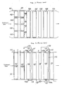
- the tertiary superheater 2 and the secondary reheater 3 disposed in parallel both have their heat transfer tube outer diameters, their tube pitches in the widthwise direction of the flue, their tube pitches in the direction of the gas flow and their numbers of tube raws in the direction of the gas flow all chosen to be identical, so that along the widthwise direction of the flue their resistances against the gas flow can be held under the identical condition.
- the secondary superheater 4 and the primary reheater 5 disposed in parallel on the gas downstream side of the above-mentioned units also have their heat transfer tube outer diameters, their tube pitches in the widthwise direction of the flue, their tube pitches in the direction of the gas flow and their number of tube raws in the direction of the gas flow all chosen to be identical, so that along the widthwise direction of the flue their resistances against the gas flow can be held under the identical condition.
- the tertiary, i.e., the high-temperature side superheater 2 and the secondary, i.e., the high-temperature side reheater 3 to be disposed in parallel
- the secondary, i.e., the low-temperature side superheater 4 and the primary, i.e., the low-temperature side reheater 5 to be disposed in parallel in such manner that along the widthwise direction of the flue their resistances against the gas flow may be held under the identical condition, a draft loss on the gas side can be held under the identical condition, hence always constant gas flows, and accordingly, there is no need to provide partition walls for specially dividing gas paths between these superheaters and reheaters to be disposed in parallel.
- the present invention is applicable equally to an exhaust gas boiler not including the deaerator 17 and the low-pressure economizer 13.
- the present invention can be applied also to an exhaust gas boiler not having the medium-pressure superheater 9.
- the primary superheater 6 can be omitted.
- the gas flow in the region extending in the widthwise direction of the flue of the superheaters and the reheaters disposed in parallel can be always maintained constant without providing partition walls for dividing gas paths between the high-temperature side superheater and the high-temperature side reheater and between the low-temperature side superheater and the low-temperature side reheater which are respectively disposed in parallel in the most upstream portion with respect to the direction of the exhaust gas flow within the reheat type exhaust gas boiler main body, recovery of heat from exhaust gas can be achieved effectively while simplifying the structure of the exhaust gas boiler.
Landscapes
- Engineering & Computer Science (AREA)
- Mechanical Engineering (AREA)
- General Engineering & Computer Science (AREA)
- Chemical & Material Sciences (AREA)
- Combustion & Propulsion (AREA)
- Life Sciences & Earth Sciences (AREA)
- Sustainable Development (AREA)
- Sustainable Energy (AREA)
- Physics & Mathematics (AREA)
- Thermal Sciences (AREA)
- Engine Equipment That Uses Special Cycles (AREA)
- Heat-Exchange Devices With Radiators And Conduit Assemblies (AREA)
Priority Applications (2)
| Application Number | Priority Date | Filing Date | Title |
|---|---|---|---|
| AT89117784T ATE83549T1 (de) | 1989-09-26 | 1989-09-26 | Abhitzekessel mit zwischenueberhitzer. |
| DE1989603954 DE68903954T2 (de) | 1989-09-26 | 1989-09-26 | Abhitzekessel mit zwischenueberhitzer. |
Applications Claiming Priority (1)
| Application Number | Priority Date | Filing Date | Title |
|---|---|---|---|
| JP63183677A JP2516661B2 (ja) | 1988-07-25 | 1988-07-25 | 再熱式排ガスボイラ |
Publications (2)
| Publication Number | Publication Date |
|---|---|
| EP0419696A1 true EP0419696A1 (de) | 1991-04-03 |
| EP0419696B1 EP0419696B1 (de) | 1992-12-16 |
Family
ID=16139994
Family Applications (1)
| Application Number | Title | Priority Date | Filing Date |
|---|---|---|---|
| EP89117784A Expired EP0419696B1 (de) | 1988-07-25 | 1989-09-26 | Abhitzekessel mit Zwischenüberhitzer |
Country Status (3)
| Country | Link |
|---|---|
| US (1) | US4944252A (de) |
| EP (1) | EP0419696B1 (de) |
| JP (1) | JP2516661B2 (de) |
Families Citing this family (11)
| Publication number | Priority date | Publication date | Assignee | Title |
|---|---|---|---|---|
| US5311844A (en) * | 1992-03-27 | 1994-05-17 | Foster Wheeler Energy Corporation | Internested superheater and reheater tube arrangement for heat recovery steam generator |
| US5247991A (en) * | 1992-05-29 | 1993-09-28 | Foster Wheeler Energy Corporation | Heat exchanger unit for heat recovery steam generator |
| JP3727668B2 (ja) * | 1993-09-17 | 2005-12-14 | 三菱重工業株式会社 | 排ガスボイラ |
| US5623822A (en) * | 1995-05-23 | 1997-04-29 | Montenay International Corp. | Method of operating a waste-to-energy plant having a waste boiler and gas turbine cycle |
| US6220013B1 (en) * | 1999-09-13 | 2001-04-24 | General Electric Co. | Multi-pressure reheat combined cycle with multiple reheaters |
| JP3956814B2 (ja) | 2002-09-18 | 2007-08-08 | トヨタ自動車株式会社 | 高電圧機器収納箱 |
| US20140041359A1 (en) * | 2012-08-13 | 2014-02-13 | Babcock & Wilcox Power Generation Group, Inc. | Rapid startup heat recovery steam generator |
| DE102012217514A1 (de) * | 2012-09-27 | 2014-03-27 | Siemens Aktiengesellschaft | Gas- und Dampfturbinenanlage mit Speisewasser-Teilstrom-Entgaser |
| WO2014132319A1 (ja) * | 2013-02-26 | 2014-09-04 | 株式会社 日立製作所 | ボイラ |
| US20170010053A1 (en) * | 2015-07-09 | 2017-01-12 | Alstom Technology Ltd | Tube arrangement in a once-through horizontal evaporator |
| US12078084B1 (en) * | 2023-02-10 | 2024-09-03 | Rtx Corporation | Increased water heat absorption capacity for steam injected turbine engine |
Citations (3)
| Publication number | Priority date | Publication date | Assignee | Title |
|---|---|---|---|---|
| FR1120404A (fr) * | 1954-05-03 | 1956-07-05 | Siemens Ag | Chaudière à haute pression avec surchauffe intermédiaire simple ou multiple par les gaz et fumées |
| EP0191415A1 (de) * | 1985-02-14 | 1986-08-20 | Mitsubishi Jukogyo Kabushiki Kaisha | Abhitzekessel für Auspuffgase |
| EP0192044A1 (de) * | 1985-02-20 | 1986-08-27 | Mitsubishi Jukogyo Kabushiki Kaisha | Kessel mit hinterem Rauchgaszug |
Family Cites Families (9)
| Publication number | Priority date | Publication date | Assignee | Title |
|---|---|---|---|---|
| US2170345A (en) * | 1935-12-18 | 1939-08-22 | Babcock & Wilcox Co | Vapor generator |
| US2699758A (en) * | 1946-02-02 | 1955-01-18 | Svenska Maskinverken Ab | Method of preheating combustion supporting air for steam generating plants |
| GB1037995A (en) * | 1962-06-15 | 1966-08-03 | Babcock & Wilcox Ltd | Improvements in or relating to tubulous vapour generators of the forced flow, once through type |
| US4188916A (en) * | 1978-05-15 | 1980-02-19 | Deltak Corporation | Waste heat boiler for abstraction of heat energy from gaseous effluent containing corrosive chemical contaminants |
| DE2950622A1 (de) * | 1979-12-15 | 1981-10-08 | Evt Energie- Und Verfahrenstechnik Gmbh, 7000 Stuttgart | Verfahren zum betreiben eines zwangdurchlaufdampferzeugers |
| DE3166099D1 (en) * | 1980-12-23 | 1984-10-25 | Sulzer Ag | Forced-circulation steam boiler |
| JPS6155501A (ja) * | 1984-08-24 | 1986-03-20 | 株式会社日立製作所 | 排熱回収ボイラ |
| US4685426A (en) * | 1986-05-05 | 1987-08-11 | The Babcock & Wilcox Company | Modular exhaust gas steam generator with common boiler casing |
| JPH0718525B2 (ja) * | 1987-05-06 | 1995-03-06 | 株式会社日立製作所 | 排ガスボイラ |
-
1988
- 1988-07-25 JP JP63183677A patent/JP2516661B2/ja not_active Expired - Fee Related
-
1989
- 1989-09-25 US US07/412,323 patent/US4944252A/en not_active Expired - Lifetime
- 1989-09-26 EP EP89117784A patent/EP0419696B1/de not_active Expired
Patent Citations (3)
| Publication number | Priority date | Publication date | Assignee | Title |
|---|---|---|---|---|
| FR1120404A (fr) * | 1954-05-03 | 1956-07-05 | Siemens Ag | Chaudière à haute pression avec surchauffe intermédiaire simple ou multiple par les gaz et fumées |
| EP0191415A1 (de) * | 1985-02-14 | 1986-08-20 | Mitsubishi Jukogyo Kabushiki Kaisha | Abhitzekessel für Auspuffgase |
| EP0192044A1 (de) * | 1985-02-20 | 1986-08-27 | Mitsubishi Jukogyo Kabushiki Kaisha | Kessel mit hinterem Rauchgaszug |
Also Published As
| Publication number | Publication date |
|---|---|
| US4944252A (en) | 1990-07-31 |
| JPH0233501A (ja) | 1990-02-02 |
| EP0419696B1 (de) | 1992-12-16 |
| JP2516661B2 (ja) | 1996-07-24 |
Similar Documents
| Publication | Publication Date | Title |
|---|---|---|
| US6173679B1 (en) | Waste-heat steam generator | |
| US5293842A (en) | Method for operating a system for steam generation, and steam generator system | |
| US4751054A (en) | Apparatus for removing NOx from a gas | |
| JPH03170701A (ja) | 貫流蒸気発生器 | |
| EP0419696B1 (de) | Abhitzekessel mit Zwischenüberhitzer | |
| CN107002987B (zh) | 用于hrsg的直流竖直管式超临界蒸发器盘管 | |
| US6125634A (en) | Power plant | |
| GB2126323A (en) | Steam generaters | |
| EP0191415B1 (de) | Abhitzekessel für Auspuffgase | |
| CN1177995A (zh) | 运行燃气和蒸汽轮机装置的方法和按此方法工作的装置 | |
| GB907192A (en) | Improvements in or relating to forced flow once-through boilers | |
| JP2753169B2 (ja) | 複圧式排熱回収ボイラ | |
| JP2002147701A (ja) | 排熱回収蒸気発生装置 | |
| US2842103A (en) | Method for washing out the conduits of supercritical pressure, water tube, vapor generators | |
| GB942036A (en) | Improvements in and relating to tubulous heat exchange units | |
| GB1029789A (en) | Once through vapor generator | |
| JPS637244B2 (de) | ||
| US3590787A (en) | Startup system | |
| US2874543A (en) | Steam power plant including reheat boiler cycle | |
| GB1142692A (en) | Supercharged vapor generator | |
| JPH03117801A (ja) | 排熱回収ボイラ | |
| CN224080178U (zh) | 一种共用省煤器的双压燃机余热锅炉 | |
| RU2775748C1 (ru) | Пароперегреватель турбоустановки | |
| GB1150165A (en) | Supercharged Vapor Generator. | |
| GB2100408A (en) | Method of and apparatus for regulating the temperature of heat exchanger supply gas |
Legal Events
| Date | Code | Title | Description |
|---|---|---|---|
| PUAI | Public reference made under article 153(3) epc to a published international application that has entered the european phase |
Free format text: ORIGINAL CODE: 0009012 |
|
| 17P | Request for examination filed |
Effective date: 19891023 |
|
| AK | Designated contracting states |
Kind code of ref document: A1 Designated state(s): AT BE DE GB IT |
|
| 17Q | First examination report despatched |
Effective date: 19920430 |
|
| GRAA | (expected) grant |
Free format text: ORIGINAL CODE: 0009210 |
|
| AK | Designated contracting states |
Kind code of ref document: B1 Designated state(s): AT BE DE GB IT |
|
| REF | Corresponds to: |
Ref document number: 83549 Country of ref document: AT Date of ref document: 19930115 Kind code of ref document: T |
|
| REF | Corresponds to: |
Ref document number: 68903954 Country of ref document: DE Date of ref document: 19930128 |
|
| ITF | It: translation for a ep patent filed | ||
| PLBE | No opposition filed within time limit |
Free format text: ORIGINAL CODE: 0009261 |
|
| STAA | Information on the status of an ep patent application or granted ep patent |
Free format text: STATUS: NO OPPOSITION FILED WITHIN TIME LIMIT |
|
| 26N | No opposition filed | ||
| REG | Reference to a national code |
Ref country code: GB Ref legal event code: IF02 |
|
| PGFP | Annual fee paid to national office [announced via postgrant information from national office to epo] |
Ref country code: AT Payment date: 20040913 Year of fee payment: 16 |
|
| PGFP | Annual fee paid to national office [announced via postgrant information from national office to epo] |
Ref country code: GB Payment date: 20040922 Year of fee payment: 16 |
|
| PGFP | Annual fee paid to national office [announced via postgrant information from national office to epo] |
Ref country code: DE Payment date: 20040923 Year of fee payment: 16 |
|
| PGFP | Annual fee paid to national office [announced via postgrant information from national office to epo] |
Ref country code: BE Payment date: 20041122 Year of fee payment: 16 |
|
| PG25 | Lapsed in a contracting state [announced via postgrant information from national office to epo] |
Ref country code: IT Free format text: LAPSE BECAUSE OF NON-PAYMENT OF DUE FEES;WARNING: LAPSES OF ITALIAN PATENTS WITH EFFECTIVE DATE BEFORE 2007 MAY HAVE OCCURRED AT ANY TIME BEFORE 2007. THE CORRECT EFFECTIVE DATE MAY BE DIFFERENT FROM THE ONE RECORDED. Effective date: 20050926 Ref country code: GB Free format text: LAPSE BECAUSE OF NON-PAYMENT OF DUE FEES Effective date: 20050926 Ref country code: AT Free format text: LAPSE BECAUSE OF NON-PAYMENT OF DUE FEES Effective date: 20050926 |
|
| PG25 | Lapsed in a contracting state [announced via postgrant information from national office to epo] |
Ref country code: BE Free format text: LAPSE BECAUSE OF NON-PAYMENT OF DUE FEES Effective date: 20050930 |
|
| PG25 | Lapsed in a contracting state [announced via postgrant information from national office to epo] |
Ref country code: DE Free format text: LAPSE BECAUSE OF NON-PAYMENT OF DUE FEES Effective date: 20060401 |
|
| GBPC | Gb: european patent ceased through non-payment of renewal fee |
Effective date: 20050926 |
|
| BERE | Be: lapsed |
Owner name: MITSUBISHI *JUKOGYO K.K. Effective date: 20050930 |