EP0419780A2 - Lampe à tube fluorescent - Google Patents
Lampe à tube fluorescent Download PDFInfo
- Publication number
- EP0419780A2 EP0419780A2 EP90112982A EP90112982A EP0419780A2 EP 0419780 A2 EP0419780 A2 EP 0419780A2 EP 90112982 A EP90112982 A EP 90112982A EP 90112982 A EP90112982 A EP 90112982A EP 0419780 A2 EP0419780 A2 EP 0419780A2
- Authority
- EP
- European Patent Office
- Prior art keywords
- lamp
- screw ring
- cutouts
- projections
- edge
- Prior art date
- Legal status (The legal status is an assumption and is not a legal conclusion. Google has not performed a legal analysis and makes no representation as to the accuracy of the status listed.)
- Granted
Links
- 230000001681 protective effect Effects 0.000 claims abstract description 28
- 230000008878 coupling Effects 0.000 claims abstract description 11
- 238000010168 coupling process Methods 0.000 claims abstract description 11
- 238000005859 coupling reaction Methods 0.000 claims abstract description 11
- 238000007789 sealing Methods 0.000 claims 1
- 238000010276 construction Methods 0.000 description 2
- 230000005855 radiation Effects 0.000 description 2
- 230000004323 axial length Effects 0.000 description 1
- 230000015572 biosynthetic process Effects 0.000 description 1
- 238000006073 displacement reaction Methods 0.000 description 1
- 230000017525 heat dissipation Effects 0.000 description 1
- 238000003780 insertion Methods 0.000 description 1
- 230000037431 insertion Effects 0.000 description 1
- 230000003993 interaction Effects 0.000 description 1
- 238000004519 manufacturing process Methods 0.000 description 1
- 238000000034 method Methods 0.000 description 1
Images

Classifications
-
- F—MECHANICAL ENGINEERING; LIGHTING; HEATING; WEAPONS; BLASTING
- F21—LIGHTING
- F21V—FUNCTIONAL FEATURES OR DETAILS OF LIGHTING DEVICES OR SYSTEMS THEREOF; STRUCTURAL COMBINATIONS OF LIGHTING DEVICES WITH OTHER ARTICLES, NOT OTHERWISE PROVIDED FOR
- F21V17/00—Fastening of component parts of lighting devices, e.g. shades, globes, refractors, reflectors, filters, screens, grids or protective cages
- F21V17/06—Fastening of component parts of lighting devices, e.g. shades, globes, refractors, reflectors, filters, screens, grids or protective cages the fastening being onto or by the lampholder
Definitions
- the invention relates to a luminaire for a fluorescent lamp with a translucent protective tube enclosing the lamp according to the features of the preamble of claim 1.
- Luminaires of this type which are designed for increased protection conditions, have such protective tubes, which are overlapped at the ends by screw rings, which are screwed tightly and tightly to the sockets and which accommodate seals at their free ends and carry seals which bear against the protective tube.
- Such lights have proven themselves, but their assembly is difficult:
- the fluorescent lamps have contact pin pairs at the end, which are inserted laterally into the voltage-carrying sockets, whereupon the lamp must be rotated by 90 ° so that the contact pins get into the contact-making position of the socket and further the lamp is prevented from sliding out of the socket by itself. A certain amount of force is required for this rotary movement and also for the lateral insertion, this presupposes that the lamp can also be properly gripped manually.
- the protective tube stands in the way of this manual access. So far it has been used to make the protective tube about 20 to 25 mm shorter than the lamp itself, so that when mounting at least on one side of the lamp so much space is left between the protective tube and the socket, so with two fingers the lamp can be gripped, held and turned by hand. So that the light is appropriately sealed with these short protective tubes, the screw ring must now be so long that it can grip the protective tube end reliably and tightly. As a result, however, the screw ring extends exactly over that area of the lamp in which the electrodes of the lamp are arranged and in which most of the heat is generated during operation. This axially long screw ring not only hinders the light but also the heat radiation, for which reason metallic sleeves have been used here in known designs to promote heat dissipation, but this is a technically unsatisfactory solution.
- the invention aims to improve these known constructions so that the lamp can be assembled more easily without obstructing the heat and light radiation by the long screw rings which were previously necessary.
- the invention proposes measures which are the content and subject of the characterizing part of the patent are 1.
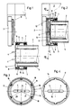
- FIG. 1 and 2 show a longitudinal section through one end of a lamp, the two representations illustrating different moments when the lamp is inserted;
- Figure 3 is a view of the disc along the section line III-III in Figure 1;
- Figure 4 is a view corresponding to Figure 3, but in a different embodiment;
- Fig. 5 shows a longitudinal section through a further embodiment of the invention.
- the lamp shown in Figures 1 and 2 has a basically known structure: on a lamp bar 1, in which the wiring and the devices necessary for the operation of the fluorescent lamp 2 are, sockets 3 are provided at the end, with the usual rotary star to the side Insert the contact pins 4 of the lamp 2 and then turn the lamp by 90 °, thereby bringing the contact pins 4 into the contacting position with the live parts of the socket 3.
- the lamp 2 is surrounded by a translucent protective tube 5 which, as can be seen from FIGS. 1 and 2, is almost as long as the lamp 2.
- screw rings 6 are provided at the end with an outer seal 7 which abuts on the outer circumference of the protective tube 5, and with an internal thread 8, which can be screwed onto the external thread 9 of the socket 3.
- nose-like projections 11 are arranged along the inner circumference of the inner wall of the screw ring 6 at equal intervals, which have a wedge-like suit 12 with an adjoining, radially outward offset section 13, so that a paragraph is formed.
- a disk 14 In the end region of the protective tube 5, a disk 14 is provided with a centrally located, elongated recess 15 through which the contact pins 4 of the lamp 2 protrude.
- the edge 16 of this disc 14 is flanged and directed against the protective tube 5.
- the flanged edge 16 of the disk 14 also has a radially projecting ring zone 17.
- a plurality of U-shaped cutouts 18 are provided which are arranged at equal distances from one another. The number of these cutouts 18, their distribution and their arrangement corresponds to the number, arrangement and distribution of the nose-like projections 11 on the screw ring 6.
- the boundary surface 19 provided between the two legs of each cutout 18 is expediently slightly inclined, the angle of inclination, based on the axis of the lamp 2, opening outwards.
- the radial distance 20 of this boundary surface 19 is slightly larger than the radial distance 21 of the highest points of the nose-like projections 11.
- the procedure is as follows: The lamp 2 is inserted into the protective tube 5, which is approximately as long as the lamp itself.
- the lamp 2 is now inserted together with the protective tube 5 and the screw rings 6 from below (FIG. 1) into the socket 13, the lamp 2, the sheathing be 14 and the screw ring 6 are approximately concentric with each other. If the contact pins 4 of the lamp 2 are retracted into the socket 3 from the side (FIG. 1), the screw rings 6 are now rotated by 90 °, and this rotary movement is followed by the disk 14, which has a positive fit via the recesses 18 and the projections 11 is connected to the screw ring 6, and the lamp 2, which is positively connected to the disk 14 via its contact pins 4 and the recess 15.
- the projections 11 are provided on the inside of the screw rings 6 and the cutouts 18 in the outer ring zone 17 of the disk 14, it is fundamentally possible to reverse the arrangement of these active elements, that is to say to arrange tooth-like tabs on the ring zone 17 and on the inside of the screw ring 6 corresponding longitudinal grooves that can extend through the thread 8.
- the edge 16 of the disk 14 is also flanged and provided with a radially projecting ring zone 17.
- such a flat design of the disk 14 would require a somewhat larger overall length of the screw ring 6.
- FIG. 5 shows another embodiment of the invention in the representation according to FIG. 2, the same being used in this figure to designate it and equivalent parts, the same reference numbers are used.
- the disk 14 here has a conical collar 22 which opens towards the protective tube 5 and which has teeth 23 on its outside which extend in the direction of the cone-producing members.
- a shoulder 24 is formed adjacent to the internal thread 8 of the screw ring 6, conically corresponding to the collar 22 of the washer 14 with teeth 25 corresponding to its teeth 23.
- the described exemplary embodiments show that fundamentally different components can be used as coupling elements and counter-elements; in one case there are nose-like projections and grooves that interact in a form-fitting manner, and in the other case (FIG. 5) there are toothed sections.
- other profiles would also be possible in principle, for example corrugations, which come into positive connection with one another or can be released from such a positive connection due to the axial displacement of the construction parts discussed here. Since the forces to be transmitted during assembly are not too great, surfaces with high friction values could also be used as coupling elements and counter elements.
- the choice of the corresponding coupling elements and counter-elements is primarily based on manufacturing considerations.
- the solution proposed according to the invention is extremely expedient since it can be used in practice with all standard sockets, it is only necessary to replace the screw ring and insert the washer 14.
- the figures also illustrate that the screw ring 6 covers the end of the protective tube 5 only over a small area, so that light and heat can flow out of the electrode area of the lamp 2 almost unimpeded.
Landscapes
- Engineering & Computer Science (AREA)
- General Engineering & Computer Science (AREA)
- Fastening Of Light Sources Or Lamp Holders (AREA)
Applications Claiming Priority (2)
| Application Number | Priority Date | Filing Date | Title |
|---|---|---|---|
| AT222489A AT397707B (de) | 1989-09-25 | 1989-09-25 | Leuchte für eine leuchtstofflampe |
| AT2224/89 | 1989-09-25 |
Publications (3)
| Publication Number | Publication Date |
|---|---|
| EP0419780A2 true EP0419780A2 (fr) | 1991-04-03 |
| EP0419780A3 EP0419780A3 (en) | 1991-10-23 |
| EP0419780B1 EP0419780B1 (fr) | 1994-11-02 |
Family
ID=3530336
Family Applications (1)
| Application Number | Title | Priority Date | Filing Date |
|---|---|---|---|
| EP19900112982 Expired - Lifetime EP0419780B1 (fr) | 1989-09-25 | 1990-07-07 | Lampe à tube fluorescent |
Country Status (3)
| Country | Link |
|---|---|
| EP (1) | EP0419780B1 (fr) |
| AT (1) | AT397707B (fr) |
| DE (1) | DE59007624D1 (fr) |
Cited By (5)
| Publication number | Priority date | Publication date | Assignee | Title |
|---|---|---|---|---|
| DE9104317U1 (de) * | 1991-04-10 | 1991-10-10 | Zumtobel Ag, Dornbirn | Überwurfring zur Abdichtung einer Leuchtstofflampe oder eines Schutzrohres einer Leuchtstofflampenleuchte an einer Fassung |
| DE4129219A1 (de) * | 1991-09-03 | 1993-03-04 | Wismeth Wolfgang | Lampengehaeuse |
| EP1036981A2 (fr) | 1999-03-15 | 2000-09-20 | NORKA Norddeutsche Kunststoff- und Elektro-Gesellschaft Stäcker & Co. mbH | Dispositif d' éclairage pour lampes allongées et procédé de montage de lampes allongées |
| EP1036980A3 (fr) * | 1999-03-15 | 2002-01-09 | NORKA Norddeutsche Kunststoff- und Elektro-Gesellschaft Stäcker & Co. mbH | Dispositif d'éclairage pour une lampe allongée |
| DE4412902B4 (de) * | 1993-05-03 | 2007-02-08 | Oc Oerlikon Balzers Ag | Verfahren zur plasmaunterstützten, chemischen Dampfabscheidung und Vakuumplasmakammer |
Family Cites Families (4)
| Publication number | Priority date | Publication date | Assignee | Title |
|---|---|---|---|---|
| US3673401A (en) * | 1969-10-29 | 1972-06-27 | Thermoplastic Processes Inc | Fluorescent lamp protection apparatus |
| CH528701A (de) * | 1971-08-17 | 1972-09-30 | Knobel Elektro App Bau Ag F | Vorrichtung an einer Fluoreszenzröhre zum Einstellen der Richtung und/oder der Grösse des Lichtstromes |
| DE3311164C2 (de) * | 1983-03-26 | 1986-03-06 | Brökelmann, Jaeger & Busse GmbH & Co, 5760 Arnsberg | Feuchtigkeitsgeschützte Fassung für eine Leuchtstoffröhrenlampe |
| DE3740701A1 (de) * | 1987-12-01 | 1989-06-15 | Trilux Lenze Gmbh & Co Kg Nehe | Leuchte mit leuchtstofflampe |
-
1989
- 1989-09-25 AT AT222489A patent/AT397707B/de not_active IP Right Cessation
-
1990
- 1990-07-07 EP EP19900112982 patent/EP0419780B1/fr not_active Expired - Lifetime
- 1990-07-07 DE DE59007624T patent/DE59007624D1/de not_active Expired - Fee Related
Cited By (8)
| Publication number | Priority date | Publication date | Assignee | Title |
|---|---|---|---|---|
| DE9104317U1 (de) * | 1991-04-10 | 1991-10-10 | Zumtobel Ag, Dornbirn | Überwurfring zur Abdichtung einer Leuchtstofflampe oder eines Schutzrohres einer Leuchtstofflampenleuchte an einer Fassung |
| DE4129219A1 (de) * | 1991-09-03 | 1993-03-04 | Wismeth Wolfgang | Lampengehaeuse |
| DE4412902B4 (de) * | 1993-05-03 | 2007-02-08 | Oc Oerlikon Balzers Ag | Verfahren zur plasmaunterstützten, chemischen Dampfabscheidung und Vakuumplasmakammer |
| EP1036981A2 (fr) | 1999-03-15 | 2000-09-20 | NORKA Norddeutsche Kunststoff- und Elektro-Gesellschaft Stäcker & Co. mbH | Dispositif d' éclairage pour lampes allongées et procédé de montage de lampes allongées |
| DE19911377A1 (de) * | 1999-03-15 | 2000-09-28 | Norka Norddeutsche Kunststoff | Leuchte für langgestreckte Lampen und Verfahren zur Montage von langgestreckten Lampen |
| EP1036981A3 (fr) * | 1999-03-15 | 2002-01-09 | NORKA Norddeutsche Kunststoff- und Elektro-Gesellschaft Stäcker & Co. mbH | Dispositif d' éclairage pour lampes allongées et procédé de montage de lampes allongées |
| EP1036980A3 (fr) * | 1999-03-15 | 2002-01-09 | NORKA Norddeutsche Kunststoff- und Elektro-Gesellschaft Stäcker & Co. mbH | Dispositif d'éclairage pour une lampe allongée |
| DE19911377B4 (de) * | 1999-03-15 | 2004-02-19 | NORKA Norddeutsche Kunststoff- und Elektro-Gesellschaft Stäcker & Co. mbH | Leuchte für langgestreckte Lampen und Verfahren zur Montage von langgestreckten Lampen |
Also Published As
| Publication number | Publication date |
|---|---|
| ATA222489A (de) | 1993-10-15 |
| DE59007624D1 (de) | 1994-12-08 |
| EP0419780B1 (fr) | 1994-11-02 |
| EP0419780A3 (en) | 1991-10-23 |
| AT397707B (de) | 1994-06-27 |
Similar Documents
| Publication | Publication Date | Title |
|---|---|---|
| DE19621432A1 (de) | Baugruppe zur Verbindung eines Betätigungsorgans mit einem Drehabsperrorgan | |
| EP0024060B1 (fr) | Lampe électrique avec un culot sous forme de douille | |
| DE3121077A1 (de) | "niederdruckquecksilberdampfentladungslampe" | |
| DE2157124B2 (de) | Koptschraube mit Unterlegscheibe | |
| DE7526777U (de) | Elektrische lampe mit sockelplatte | |
| EP0024363B1 (fr) | Lampe électrique avec un culot sous forme de douille | |
| EP4181326B1 (fr) | Élément de contact pour connecter un module électrique ou électronique à un rail de support de luminaire allongé | |
| EP0141021B1 (fr) | Douille pour lampe à incandescence | |
| DE2941011C2 (fr) | ||
| EP0419780B1 (fr) | Lampe à tube fluorescent | |
| DE1489616A1 (de) | Gasentladungslampe | |
| EP1852651A1 (fr) | Réflecteur pour un dispositif d'éclairage | |
| EP0400318B1 (fr) | Armature pour lampe à décharge, en particulier pour lampe fluorescente | |
| DE3510856C2 (fr) | ||
| DE19957977B4 (de) | Vorrichtung aus Abdeckelement und Gewindebolzen | |
| DE3728528A1 (de) | Elektrokochplatten-anschlussstueck | |
| DE3629779C1 (en) | Electrical series terminal arrangement | |
| DE7929989U1 (de) | Halter zum Festsetzen von lose eingesetzten Teilen in einem Gehäuse | |
| DE10049642C2 (de) | Lampenträgereinrichtung für Halogen-Hochvoltlampen mit Zweistiftsockel, insbesondere Sockel GU10 oder GZ10, an einer Strahlerleuchte | |
| AT392343B (de) | Fassung fuer eine leuchte fuer leuchtstofflampen | |
| EP0491249B1 (fr) | Porte-socle, installé dans une armature d'éclairage d'au moins une lampe fluorescente (tubulaire) avec des douilles à double fiche | |
| DE598054C (de) | Tragvorrichtung fuer Gruppen von elektrischen Gluehlampen, bei welcher das Fassungsgewinde aus einem schraubenfoermig gewundenen federnden Metalldraht besteht | |
| DE4003130A1 (de) | Kindersicherung fuer steckdosen | |
| EP1329931A2 (fr) | Lampe compacte à décharge à basse pression | |
| DE19917139B4 (de) | Halterung für eine Lampe |
Legal Events
| Date | Code | Title | Description |
|---|---|---|---|
| PUAI | Public reference made under article 153(3) epc to a published international application that has entered the european phase |
Free format text: ORIGINAL CODE: 0009012 |
|
| AK | Designated contracting states |
Kind code of ref document: A2 Designated state(s): CH DE FR IT LI |
|
| PUAL | Search report despatched |
Free format text: ORIGINAL CODE: 0009013 |
|
| AK | Designated contracting states |
Kind code of ref document: A3 Designated state(s): CH DE FR IT LI |
|
| 17P | Request for examination filed |
Effective date: 19920116 |
|
| 17Q | First examination report despatched |
Effective date: 19930902 |
|
| GRAA | (expected) grant |
Free format text: ORIGINAL CODE: 0009210 |
|
| AK | Designated contracting states |
Kind code of ref document: B1 Designated state(s): CH DE FR IT LI |
|
| REF | Corresponds to: |
Ref document number: 59007624 Country of ref document: DE Date of ref document: 19941208 |
|
| ITF | It: translation for a ep patent filed | ||
| ET | Fr: translation filed | ||
| PLBE | No opposition filed within time limit |
Free format text: ORIGINAL CODE: 0009261 |
|
| STAA | Information on the status of an ep patent application or granted ep patent |
Free format text: STATUS: NO OPPOSITION FILED WITHIN TIME LIMIT |
|
| 26N | No opposition filed | ||
| PGFP | Annual fee paid to national office [announced via postgrant information from national office to epo] |
Ref country code: FR Payment date: 20010730 Year of fee payment: 12 |
|
| PG25 | Lapsed in a contracting state [announced via postgrant information from national office to epo] |
Ref country code: FR Free format text: LAPSE BECAUSE OF NON-PAYMENT OF DUE FEES Effective date: 20030331 |
|
| REG | Reference to a national code |
Ref country code: FR Ref legal event code: ST |
|
| PGFP | Annual fee paid to national office [announced via postgrant information from national office to epo] |
Ref country code: DE Payment date: 20080915 Year of fee payment: 19 Ref country code: CH Payment date: 20080917 Year of fee payment: 19 |
|
| PGFP | Annual fee paid to national office [announced via postgrant information from national office to epo] |
Ref country code: IT Payment date: 20080729 Year of fee payment: 19 |
|
| REG | Reference to a national code |
Ref country code: CH Ref legal event code: PL |
|
| PG25 | Lapsed in a contracting state [announced via postgrant information from national office to epo] |
Ref country code: LI Free format text: LAPSE BECAUSE OF NON-PAYMENT OF DUE FEES Effective date: 20090731 Ref country code: CH Free format text: LAPSE BECAUSE OF NON-PAYMENT OF DUE FEES Effective date: 20090731 |
|
| PG25 | Lapsed in a contracting state [announced via postgrant information from national office to epo] |
Ref country code: DE Free format text: LAPSE BECAUSE OF NON-PAYMENT OF DUE FEES Effective date: 20100202 |
|
| PG25 | Lapsed in a contracting state [announced via postgrant information from national office to epo] |
Ref country code: IT Free format text: LAPSE BECAUSE OF NON-PAYMENT OF DUE FEES Effective date: 20090707 |