EP1036981A2 - Dispositif d' éclairage pour lampes allongées et procédé de montage de lampes allongées - Google Patents
Dispositif d' éclairage pour lampes allongées et procédé de montage de lampes allongées Download PDFInfo
- Publication number
- EP1036981A2 EP1036981A2 EP00105183A EP00105183A EP1036981A2 EP 1036981 A2 EP1036981 A2 EP 1036981A2 EP 00105183 A EP00105183 A EP 00105183A EP 00105183 A EP00105183 A EP 00105183A EP 1036981 A2 EP1036981 A2 EP 1036981A2
- Authority
- EP
- European Patent Office
- Prior art keywords
- lamp
- socket housing
- lamp cover
- cover
- luminaire
- Prior art date
- Legal status (The legal status is an assumption and is not a legal conclusion. Google has not performed a legal analysis and makes no representation as to the accuracy of the status listed.)
- Withdrawn
Links
- 238000000034 method Methods 0.000 title claims abstract description 9
- 238000003780 insertion Methods 0.000 claims description 3
- 230000037431 insertion Effects 0.000 claims description 3
- 230000001681 protective effect Effects 0.000 description 2
- 238000004026 adhesive bonding Methods 0.000 description 1
- 230000003247 decreasing effect Effects 0.000 description 1
Images

Classifications
-
- F—MECHANICAL ENGINEERING; LIGHTING; HEATING; WEAPONS; BLASTING
- F21—LIGHTING
- F21V—FUNCTIONAL FEATURES OR DETAILS OF LIGHTING DEVICES OR SYSTEMS THEREOF; STRUCTURAL COMBINATIONS OF LIGHTING DEVICES WITH OTHER ARTICLES, NOT OTHERWISE PROVIDED FOR
- F21V19/00—Fastening of light sources or lamp holders
- F21V19/04—Fastening of light sources or lamp holders with provision for changing light source, e.g. turret
-
- F—MECHANICAL ENGINEERING; LIGHTING; HEATING; WEAPONS; BLASTING
- F21—LIGHTING
- F21V—FUNCTIONAL FEATURES OR DETAILS OF LIGHTING DEVICES OR SYSTEMS THEREOF; STRUCTURAL COMBINATIONS OF LIGHTING DEVICES WITH OTHER ARTICLES, NOT OTHERWISE PROVIDED FOR
- F21V19/00—Fastening of light sources or lamp holders
- F21V19/0075—Fastening of light sources or lamp holders of tubular light sources, e.g. ring-shaped fluorescent light sources
- F21V19/008—Fastening of light sources or lamp holders of tubular light sources, e.g. ring-shaped fluorescent light sources of straight tubular light sources, e.g. straight fluorescent tubes, soffit lamps
Definitions
- the invention relates to a lamp for elongated lamps a lamp cover that encloses the lamp on all sides and with front socket housings on a luminaire body for receiving the lamp and a method for assembling elongated lamps.
- Luminaires for elongated lamps for example for linear ones Fluorescent tubes, especially in damp room lights Envelopes of the fluorescent lamp to protect it from cold, moisture, Protect dirt or mechanical influences.
- the Luminaires have socket housings on the front with contact sockets, into which the lamp is inserted with its corresponding contact pins and be snapped into place.
- the lamp cover is in suitable Sockets screwed or snapped onto the socket housing.
- Such a lamp is for example through the catalog NORKA K18 known from 1979 and there for example offered under the name "Eutin”.
- the socket housing is formed in two parts with a pressure cover, the Contact surface for the pressure cover at the height of the largest diameter the lamp and lamp cover.
- two-slot snap-in frames are used, in which the two contact pins of the lamp in the two at the same time Slits are inserted from below to the end position to be contacted with a rest.
- the end pieces must be on both sides the lamp and the complete lamp cover together with the lamp in it must be removed from the lamp body be removed.
- the lamp is then removed from the front of the lamp cover pulled out and a new lamp is inserted.
- the unit of lamp cover and lamp maintained in this way becomes then reassembled and by fitting and fastening closed by pressure covers on the socket housing.
- EP 0 419 780 A2 is a luminaire for a fluorescent lamp known, the end contact pin pairs in the version in a common slot can be introduced, which is located on one rotatable part. By rotating the lamp with the slot the contact pins reach a contact position in the Frame.
- the socket housing has a screw attachment a screw ring with a seal can be screwed on.
- the elongated lamp in the associated protective tube introduced.
- the Plate has a beaded edge, in which there are recesses are in the recesses of the axially displaceable screw ring can intervene.
- Lamp in the protective tube via the non-rotatable connection with the The plate can be rotated so that the screw ring turns 90 ° to the Contacting the lamp can be done.
- the lamp, lamp cover, Plate and screw ring formed unit completely removed and reassembled with the replaced lamp before that Inserted into the sockets of the socket housing.
- the invention is therefore based on the object of a lamp to create the type mentioned, in which the workload for the replacement of the lamp is reduced.
- this object is achieved with a lamp at the beginning mentioned type solved in that the lamp cover on a first of the front socket housings detachable and down from the first socket housing can be folded away and on the second the The front socket housing is restricted in the assembled state is tiltably attached so that the one located in the lamp cover Lamp after the lamp cover has been folded away from the first Socket housing from that mounted on the second socket housing The lamp cover can be pulled out.
- the lamp according to the invention thus enables the replacement of elongated lamp while maintaining the assembled state the lamp cover on one side of the lamp.
- the lamp cover is from the corresponding socket housing loosened and folded down so that the lamp on this side can easily be pulled out and replaced.
- the new lamp is pushed into the lamp cover and on the mounted side of the lamp cover in the socket housing at Inserted contacted. Then the lamp cover comes back on folded up and the lamp closed again. Is recognizable the work required to change the lamp considerably decreased.
- the socket housing it is proposed to use latches, e.g. To use toggle locks.
- the socket housing e.g. be closed with a clampable pressure cover, which holds the end piece of the lamp cover. It is not that more necessary, the end piece of the socket housing unscrew.
- a holding element between the End piece and the socket housing is located.
- the holding element is designed so that it is the end piece together with the Lamp cover in the released state of the lamp cover on the Socket housing secures so that a fitter can cover the lamp no longer has to hold on.
- the holding element can be tab-shaped be and have an eyelet that has a tubular protrusion of the end piece encloses.
- the tubular projection also serves for fastening the lamp cover on the socket housing.
- the holding element should still a hook at the end opposite the eyelet have, in a corresponding abutment in the socket housing hooks when the lamp cover is released.
- the holding element is thus loaded on train and by the hook on the Socket housing worn when replacing the lamp cover a lamp on one side on the first front socket housing is unscrewed.
- the holding element in the interior of the front socket housing slide in and remain there without function and unloaded.
- Such a two-hole socket has a frustoconical shape or frusto-conical contacts, which at a frontal insertion of the contact pins pressed apart and a safe electrical contact with the Contact pins Contact pins when the lamp is inserted axially produce.
- This disadvantage can be avoided if next to the second Socket housing a guide element is provided.
- This guide element can advantageously with the end piece for example be connected by inserting or gluing.
- the guide element is frustoconical or frustoconical is.
- the tapered end of the guide element in the opening of the end piece and the fanned out end is sliding Pick up the lamp during the insertion process downwards Lamp cover tilted towards.
- the guide element is an integral part of the lamp cover.
- the guide element in particular in the lamp cover be glued in.
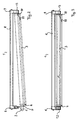
- Figure 1 leaves a lamp 1 for elongated lamps 2 in Recognize detail in which a lamp cover 3 and the lamp 2 encloses on all sides.
- the lamp 2 is inserted into an end piece 4, that closes the lamp cover 3 on the front.
- the tail 4 has a tubular projection 5 for inserting and fastening the Lamp cover 3 on a first end-shaped socket housing 6 the lamp 1.
- the lamp cover 3 as shown folded down from the lamp 1 and the lamp 2 is pulled out of the lamp cover 3.
- a tab-shaped holding element 7 is provided, which with an eyelet Pipe projection 5 encloses and at the opposite end of the Eyelet with a hook in an abutment of the first socket housing 6 engages.
- FIG. 1 also shows that the first socket housing 6 has grooves 6a to a not-shown latch for a pressure cover to the first socket housing 6 clamp and thus the lamp cover 3 in the assembled state to secure the lamp 1. Close the lid and the latch the first socket housing 6.
- FIG. 2 shows that the lamp body 8 of the lamp 1 is elongated and the first socket housing 6 and one second socket housing 9 is arranged on the face of the lamp body is.
- the socket housing 6, 9 point from the lamp body 8 vertically downwards.
- FIG. 1 leaves the lamp 1 with the lamp cover folded down 3 recognize.
- the lamp cover is used to replace the lamp 2 3 released on the first socket housing 6 and folded down while it remains mounted on the second socket housing 9.
- the attachment of the second front end piece 10 on the second socket housing 9 is such that the lamp cover 3 in one restricted angle is tiltable.
- the guide element 11 is frustoconical or frusto-conical segment around the lamp 2 at its fanned out End of the bottom of the lamp cover 3 and by means of the taper of the truncated cone towards the opening of the second Guide end piece 10.
- the guide element 11 is preferred formed as an integral part of the lamp cover 3, especially in the lamp cover 3 as a transparent part glued in.
- FIG 3 shows the lamp 1 in the assembled state.
- first front socket housing 6 outlines on which a pressure cover 13 with a Fastener 12 is attached, the pressure cover 13 the first front socket housing 6 covers form-fitting.
- second socket housing 9 On the opposite second socket housing 9 is a corresponding Pressure cover 13 provided for the second socket housing 9, which are either screwed to the second socket housing 9 or can also be designed as a latch 12.
Landscapes
- Engineering & Computer Science (AREA)
- General Engineering & Computer Science (AREA)
- Fastening Of Light Sources Or Lamp Holders (AREA)
Applications Claiming Priority (2)
| Application Number | Priority Date | Filing Date | Title |
|---|---|---|---|
| DE19911377 | 1999-03-15 | ||
| DE1999111377 DE19911377B4 (de) | 1999-03-15 | 1999-03-15 | Leuchte für langgestreckte Lampen und Verfahren zur Montage von langgestreckten Lampen |
Publications (2)
| Publication Number | Publication Date |
|---|---|
| EP1036981A2 true EP1036981A2 (fr) | 2000-09-20 |
| EP1036981A3 EP1036981A3 (fr) | 2002-01-09 |
Family
ID=7900963
Family Applications (1)
| Application Number | Title | Priority Date | Filing Date |
|---|---|---|---|
| EP00105183A Withdrawn EP1036981A3 (fr) | 1999-03-15 | 2000-03-11 | Dispositif d' éclairage pour lampes allongées et procédé de montage de lampes allongées |
Country Status (2)
| Country | Link |
|---|---|
| EP (1) | EP1036981A3 (fr) |
| DE (1) | DE19911377B4 (fr) |
Citations (1)
| Publication number | Priority date | Publication date | Assignee | Title |
|---|---|---|---|---|
| EP0419780A2 (fr) | 1989-09-25 | 1991-04-03 | Zumtobel Aktiengesellschaft | Lampe à tube fluorescent |
Family Cites Families (4)
| Publication number | Priority date | Publication date | Assignee | Title |
|---|---|---|---|---|
| GB2112513B (en) * | 1981-12-23 | 1985-07-03 | Parly Tools Manufacturing Limi | Combined fluorescent lamp and spotlight |
| DE3740701A1 (de) * | 1987-12-01 | 1989-06-15 | Trilux Lenze Gmbh & Co Kg Nehe | Leuchte mit leuchtstofflampe |
| US5727869A (en) * | 1996-06-17 | 1998-03-17 | Boyd Lighting Company | Fluorescent light fixture with breakaway socket |
| US5906427A (en) * | 1997-02-20 | 1999-05-25 | Boam R & D Co., Ltd. | Fluorescent lamp |
-
1999
- 1999-03-15 DE DE1999111377 patent/DE19911377B4/de not_active Expired - Lifetime
-
2000
- 2000-03-11 EP EP00105183A patent/EP1036981A3/fr not_active Withdrawn
Patent Citations (1)
| Publication number | Priority date | Publication date | Assignee | Title |
|---|---|---|---|---|
| EP0419780A2 (fr) | 1989-09-25 | 1991-04-03 | Zumtobel Aktiengesellschaft | Lampe à tube fluorescent |
Also Published As
| Publication number | Publication date |
|---|---|
| DE19911377A1 (de) | 2000-09-28 |
| EP1036981A3 (fr) | 2002-01-09 |
| DE19911377B4 (de) | 2004-02-19 |
Similar Documents
| Publication | Publication Date | Title |
|---|---|---|
| EP2132006B1 (fr) | Tire-goupille en plusieurs parties pour extraire une goupille ou un goujon d'un trou ménagé dans un composant | |
| EP2803308B1 (fr) | Dispositif de fixation amovible d'un siège de toilettes et procédé correspondant | |
| EP2256396A1 (fr) | Dispositif de durcissement de revêtements en matière synthétique | |
| EP0833412A2 (fr) | Broche de guidage pour connexions électriques | |
| DE69805107T2 (de) | Diebstahlfeste Montage für Leuchtstofflampen | |
| DE69015097T2 (de) | Kraftfahrzeugskarosseriekomponente, umfassend eine Beleuchtungsvorrichtung. | |
| DE19904087A1 (de) | Kupplungsstecker | |
| EP1048544B1 (fr) | Articulation pour rames de véhicules ferroviaires | |
| DE102005032197B4 (de) | Endoskopisches Instrument | |
| DE3544162A1 (de) | Anschlussvorrichtung fuer endoskop und photographisches geraet | |
| DE19803882B4 (de) | Halogenleuchte | |
| DE19911377B4 (de) | Leuchte für langgestreckte Lampen und Verfahren zur Montage von langgestreckten Lampen | |
| DE202008004448U1 (de) | Strahlerleuchte | |
| DE60002670T2 (de) | Lampenadapter mit integriertem elektronischen vorschaltgerät zur aufnahme von hochleistunsleuchtstofflampen, zum ersetzen von leuchtstofflampen mit einem induktiven vorschaltgerät | |
| DE102019119889A1 (de) | Verbindungsanordnung zwischen einer Steuereinrichtung und einem Anschlussflansch sowie Steuereinrichtung, Anschlussflansch und Steckbolzen für die Verbindungsanordnung | |
| DE3246042C2 (de) | Verbindungsvorrichtung zum Herstellen einer lösbaren Steckverbindung | |
| DE3685789T2 (de) | Voellig geschlossene armatureinrichtung fuer leuchtstoffroehre. | |
| DE19924168A1 (de) | Befestigungsvorrichtung zur Verbindung von zwei Gehäusehälften eines Installationsgerätes | |
| DE10153203A1 (de) | Haltevorrichtung für eine UV-Lampe | |
| DE102020105708A1 (de) | Gargeräteleuchte mit formschlüssig gehaltenem Lichtleitstab | |
| EP2829340B1 (fr) | Dispositif de serrage | |
| EP0961077A2 (fr) | Dispositif porte-lampe pour luminaire à bras articulés comprenant une tête d'éclairage | |
| DE202024105115U1 (de) | Lötwerkzeughalterung, Lötwerkzeug, Heizelement, Lötspitze, Lötwerkzeugbaugruppe, Handhabungssystem | |
| DE29517332U1 (de) | Lampenfassung zur Befestigung in einem Leuchtengehäuse | |
| DE202023101645U1 (de) | Baugruppe mit Bajonettverschluss |
Legal Events
| Date | Code | Title | Description |
|---|---|---|---|
| PUAI | Public reference made under article 153(3) epc to a published international application that has entered the european phase |
Free format text: ORIGINAL CODE: 0009012 |
|
| AK | Designated contracting states |
Kind code of ref document: A2 Designated state(s): AT CH DE FR LI Kind code of ref document: A2 Designated state(s): AT BE CH CY DE DK ES FI FR GB GR IE IT LI LU MC NL PT SE |
|
| AX | Request for extension of the european patent |
Free format text: AL;LT;LV;MK;RO;SI |
|
| PUAL | Search report despatched |
Free format text: ORIGINAL CODE: 0009013 |
|
| AK | Designated contracting states |
Kind code of ref document: A3 Designated state(s): AT BE CH CY DE DK ES FI FR GB GR IE IT LI LU MC NL PT SE |
|
| AX | Request for extension of the european patent |
Free format text: AL;LT;LV;MK;RO;SI |
|
| 17P | Request for examination filed |
Effective date: 20020316 |
|
| AKX | Designation fees paid |
Free format text: AT CH DE FR LI |
|
| RAP1 | Party data changed (applicant data changed or rights of an application transferred) |
Owner name: NORKA NORDDEUTSCHE KUNSTSTOFF- UNDELEKTRO-GESELLSC |
|
| 17Q | First examination report despatched |
Effective date: 20050613 |
|
| GRAP | Despatch of communication of intention to grant a patent |
Free format text: ORIGINAL CODE: EPIDOSNIGR1 |
|
| RBV | Designated contracting states (corrected) |
Designated state(s): AT CH FR LI |
|
| REG | Reference to a national code |
Ref country code: DE Ref legal event code: 8566 |
|
| STAA | Information on the status of an ep patent application or granted ep patent |
Free format text: STATUS: THE APPLICATION IS DEEMED TO BE WITHDRAWN |
|
| 18D | Application deemed to be withdrawn |
Effective date: 20070216 |