EP0420000A1 - Outil de coupe pour machine à broyer - Google Patents
Outil de coupe pour machine à broyer Download PDFInfo
- Publication number
- EP0420000A1 EP0420000A1 EP90117895A EP90117895A EP0420000A1 EP 0420000 A1 EP0420000 A1 EP 0420000A1 EP 90117895 A EP90117895 A EP 90117895A EP 90117895 A EP90117895 A EP 90117895A EP 0420000 A1 EP0420000 A1 EP 0420000A1
- Authority
- EP
- European Patent Office
- Prior art keywords
- cutting
- cutting edges
- grooves
- cutting knife
- edges
- Prior art date
- Legal status (The legal status is an assumption and is not a legal conclusion. Google has not performed a legal analysis and makes no representation as to the accuracy of the status listed.)
- Granted
Links
- 238000005520 cutting process Methods 0.000 claims abstract description 100
- 235000013372 meat Nutrition 0.000 claims description 6
- 239000000463 material Substances 0.000 abstract description 15
- 241000283690 Bos taurus Species 0.000 description 3
- 229910000831 Steel Inorganic materials 0.000 description 1
- 230000001154 acute effect Effects 0.000 description 1
- 238000010276 construction Methods 0.000 description 1
- 230000000694 effects Effects 0.000 description 1
- 230000002349 favourable effect Effects 0.000 description 1
- 235000013305 food Nutrition 0.000 description 1
- 238000010438 heat treatment Methods 0.000 description 1
- 238000000034 method Methods 0.000 description 1
- 235000015277 pork Nutrition 0.000 description 1
- 238000000926 separation method Methods 0.000 description 1
- 238000003307 slaughter Methods 0.000 description 1
- 239000010959 steel Substances 0.000 description 1
- 210000002435 tendon Anatomy 0.000 description 1
Images

Classifications
-
- B—PERFORMING OPERATIONS; TRANSPORTING
- B02—CRUSHING, PULVERISING, OR DISINTEGRATING; PREPARATORY TREATMENT OF GRAIN FOR MILLING
- B02C—CRUSHING, PULVERISING, OR DISINTEGRATING IN GENERAL; MILLING GRAIN
- B02C18/00—Disintegrating by knives or other cutting or tearing members which chop material into fragments
- B02C18/30—Mincing machines with perforated discs and feeding worms
- B02C18/36—Knives or perforated discs
Definitions
- the invention relates to a cutting set for a comminution machine, in particular for meat and the like. With a perforated disc and a drivable cutting knife interacting therewith.
- Such cutting sets and the associated shredding machines have long been used in the food industry, but in particular in the meat processing industry. They are equipped with one or more cutting sets of the type mentioned at the outset, which are arranged one behind the other in the direction of travel of the material to be cut.
- the material to be sliced which in the meat processing industry can be meat, rind, lichen and other cutable parts of the slaughter cattle, is usually supplied by means of a screw conveyor or the like.
- the cutting knife is on the same shaft as the screw conveyor or the like, so that both can be driven together at the same speed.
- the first one is used for rough cutting, while with the following ones the material to be cut is further shredded, so that in the end it leaves the outlet of the machine relatively finely shredded.
- the degree of fineness depends on the cross-section of the holes in the perforated disc.
- the object of the invention is therefore to develop a cutting set of the type mentioned so that it works with greater effectiveness.
- the invention proposes that the cutting set is designed according to the preamble of claim 1 according to the characterizing part of this claim. Now it is possible that, seen in the radial direction, between the cutting knife and the surrounding stationary part of the shredding machine, a shredding process takes place, which separates the penetrated cuttings from the remaining part of the same, seen in the direction of flow, in front of the cutting knife and thereby facilitating its feeding to the actual cutting edges of the cutting set and the perforated plate. This also prevents congestion in this outer area of the cutting set, in particular also in the outer area of the perforated disk.
- the extent to which a pure cutting process or only a comparable separation from the individual chunks of the material to be cut takes place depends on the construction of the cutting knife on the one hand and the gap width on the other hand and the comminution material itself. In any case, the hindrance to the passage or the feed to the cutting set is improved in this way and the effectiveness of this cutting set is intended to be improved, which also includes undesired local heating of the material to be cut.
- a further development of the invention provides that at least the additional cutting edges are formed by grooves, grooves or the like. Recesses in the cutting blade body. The more sharp-edged they are, the better their cutting effect.
- the cutting process can also be influenced by the cross-sectional shape, it being particularly desirable that one of the edges be one has a favorable angle.
- the grooves or the like are attached to the casing of the cutting knife body and they each run in the direction of a casing line or at a slight inclination to it.
- this does not mean that it must be a complete jacket in the sense of a cylinder or truncated cone jacket, rather it can be interrupted in a known manner.
- the grooves are only on the parts that remain from an imaginary cylindrical, frustoconical or similar shell.
- Correspondingly designed and aligned grooves can be located on the inside of the housing, which then together with the grooves of the cutting knife body form a pair of cutting edges.
- a further embodiment of the invention consists in that the jacket of the cutting knife body is frustoconical and the grooves or the like.
- the counter blades are attached to a truncated cone-shaped inner jacket.
- the cone angles are the same or approximately the same.
- the cutting knife body preferably consists of a hub with approximately radially or tangentially projecting arms, the grooves or the like being located on the free end faces of the arms. It is in particular an embodiment with several arms, preferably with five to twelve arms, although also one Knives with fewer arms can be used, as has been known for a long time.
- a preferred embodiment of the invention is characterized in that the larger truncated spherical surface of the cutting knife body faces the perforated disk and the grooves or the like of the machine housing are attached to a removable housing ring. In the event of damage or wear, the latter can easily be exchanged for a new one or, if necessary, also overhauled. It is also possible to use a different material for this ring than for the housing of the shredding machine, in particular a material that can better withstand the loads.
- the cutting knife can be advanced in the direction of its axis of rotation against its perforated disc, and at maximum cutting height, the additional cutting edges have a minimal gap distance from the counter cutting edges.
- the cutting edges of the cutting knife are preferably located on cutting blades made of particularly high-quality material, in particular knife steel, which are inserted into the cutting knife body and are therefore adjustable or adjustable after grinding. Because they still wear out and consequently the cutting knife has to be set against the perforated disc when the blade has become shorter due to regrinding, this leads to an increase in the gap distance. However, this remains within relatively small limits, so that the effectiveness of the radial cutting device is hardly negatively thereby is influenced.
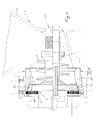
- the shredding machine 1 only partially shown, with the hopper 2 for the shredded material has a drive shaft 3 driven by an electric motor, also not shown, on which a screw conveyor 4 and a cutting knife 5 of a cutting set 6 are held in a rotationally fixed manner.
- the cutting set also includes a perforated disk 7 of a known type.
- the comminution material introduced into the filling funnel 2, for example meat, rind, pork, tendons and the like, is grasped by the screw conveyor 4 projecting into the lower end of the funnel and transported against the cutting set 6. Then it will crushed with the aid of the cutting set and leaves this machine in the direction of the arrow 8. At a suitable point, this emerging comminuted mass flow can be deflected, but this is not important in connection with the design of the cutting set according to the invention.
- the cutting knife consists, in particular, of how the FIGS. 2 and 3 can be clearly seen from a cutting knife body 9 with interchangeable and adjustable cutting blades 10 inserted therein.
- Fig. 2 at an acute angle 11 to a radius 12 through the hub 13 of the cutting blade body 9. Seen in the direction of rotation 14, the outer end of each cutting blade 10 leads ahead of the inner end.
- a fastening element 15 is indicated symbolically by a dash-dotted line.
- the cutting knife 5 consists of the already mentioned hub 13 and arms 16 which are approximately tangentially attached to it. In the exemplary embodiment, approximately tangetially, to specify it somewhat, the longitudinal rearward edge of each arm 16 in the direction of rotation Pre-cutter. It is assigned to the hub surface 18 pointing towards the inner end of the funnel.
- 16 additional cutting edges 19 are now on the cutting blade body or, in the exemplary embodiment, on the free ends of the arms attached, in particular molded, which extend in approximately the radial direction and cooperate with approximately radial counter cutting edges 20 of the machine housing, in particular a housing ring 21 of the latter, for additional comminution of the filled material.
- the additional cutting edges 19 and the counter cutting edges 20 act together in the sense of comminution if the material has forced itself into the gap 22.
- the additional cutting edges 19 run slightly inclined with respect to a surface line parallel to the geometric axis of rotation 23, their upper end leading ahead.
- the counter cutting edges 20 also have a corresponding inclination.
- the additional cutting edges and the counter cutting edges 20 receive a further inclination in that the free, front ends of the arms 16 form parts of a truncated cone surface, the smaller truncated cone surface facing the hub surface 18.
- the angle of this truncated cone is designated by 24 in FIG. 1. It is of the order of 60 ° to 70 °, while the angle of inclination 25 is of the order of 15 °.
Landscapes
- Engineering & Computer Science (AREA)
- Food Science & Technology (AREA)
- Crushing And Pulverization Processes (AREA)
Applications Claiming Priority (2)
| Application Number | Priority Date | Filing Date | Title |
|---|---|---|---|
| DE3931813A DE3931813A1 (de) | 1989-09-23 | 1989-09-23 | Schneidsatz fuer eine zerkleinerungsmaschine |
| DE3931813 | 1989-09-23 |
Publications (2)
| Publication Number | Publication Date |
|---|---|
| EP0420000A1 true EP0420000A1 (fr) | 1991-04-03 |
| EP0420000B1 EP0420000B1 (fr) | 1994-03-30 |
Family
ID=6390052
Family Applications (1)
| Application Number | Title | Priority Date | Filing Date |
|---|---|---|---|
| EP90117895A Expired - Lifetime EP0420000B1 (fr) | 1989-09-23 | 1990-09-18 | Outil de coupe pour machine à broyer |
Country Status (5)
| Country | Link |
|---|---|
| US (1) | US5054698A (fr) |
| EP (1) | EP0420000B1 (fr) |
| DE (1) | DE3931813A1 (fr) |
| DK (1) | DK0420000T3 (fr) |
| ES (1) | ES2054184T3 (fr) |
Families Citing this family (2)
| Publication number | Priority date | Publication date | Assignee | Title |
|---|---|---|---|---|
| US5918822A (en) * | 1998-01-26 | 1999-07-06 | Sternby; Arthur J. | Channeled pulp rotor |
| US8257148B1 (en) | 2009-01-06 | 2012-09-04 | Reliance Controls Corporation | Knife insert with bottom edge relief for cutting edge alignment |
Citations (2)
| Publication number | Priority date | Publication date | Assignee | Title |
|---|---|---|---|---|
| FR993726A (fr) * | 1949-03-26 | 1951-11-06 | Machine à broyer des substances animales et végétales et procédé pour la mise en valeur des graisses | |
| DE8617950U1 (de) * | 1986-07-04 | 1987-11-05 | Fryma-Maschinen Ag, Rheinfelden | Mehrstufenmühle |
Family Cites Families (6)
| Publication number | Priority date | Publication date | Assignee | Title |
|---|---|---|---|---|
| US667029A (en) * | 1899-03-15 | 1901-01-29 | Enterprise Mfg Co | Meat-cutter. |
| US2282671A (en) * | 1940-12-09 | 1942-05-12 | Lewis B Motte | Meat grinder |
| DK125313B (da) * | 1970-04-27 | 1973-02-05 | W Jensen | Hakkemaskine med transportsnegl og tilpresningssnegl. |
| DK157783C (da) * | 1977-06-17 | 1990-09-17 | Wolfking Danmark As | Hakkemaskine, isaer koedhakkemaskine |
| AT351963B (de) * | 1977-10-06 | 1979-08-27 | Laska Maschf Gmbh | Schneidsatz fuer fleischwoelfe od.dgl. |
| DE3620598C2 (de) * | 1986-06-19 | 1997-08-14 | Schnell Maschfab Karl | Vorrichtung zum automatischen Verstellen des Schneidsatzes einer Fleischzerkleinerungsmaschine |
-
1989
- 1989-09-23 DE DE3931813A patent/DE3931813A1/de not_active Withdrawn
-
1990
- 1990-09-18 DK DK90117895.4T patent/DK0420000T3/da active
- 1990-09-18 ES ES90117895T patent/ES2054184T3/es not_active Expired - Lifetime
- 1990-09-18 US US07/584,471 patent/US5054698A/en not_active Expired - Fee Related
- 1990-09-18 EP EP90117895A patent/EP0420000B1/fr not_active Expired - Lifetime
Patent Citations (2)
| Publication number | Priority date | Publication date | Assignee | Title |
|---|---|---|---|---|
| FR993726A (fr) * | 1949-03-26 | 1951-11-06 | Machine à broyer des substances animales et végétales et procédé pour la mise en valeur des graisses | |
| DE8617950U1 (de) * | 1986-07-04 | 1987-11-05 | Fryma-Maschinen Ag, Rheinfelden | Mehrstufenmühle |
Also Published As
| Publication number | Publication date |
|---|---|
| ES2054184T3 (es) | 1994-08-01 |
| DK0420000T3 (da) | 1994-05-02 |
| DE3931813A1 (de) | 1991-04-04 |
| US5054698A (en) | 1991-10-08 |
| EP0420000B1 (fr) | 1994-03-30 |
Similar Documents
| Publication | Publication Date | Title |
|---|---|---|
| DE69222030T2 (de) | Hartstoffsammelsystem für einen fleischwolf | |
| EP0329662B1 (fr) | Dispositif de traitement de matieres plastiques | |
| DE2344284A1 (de) | Schneidsatz fuer fleischwoelfe und aehnliche schneidmaschinen | |
| DE102019108306A1 (de) | Schneidmühle zum schneidenden Zerkleinern von Proben | |
| DE2840337B2 (de) | Schneidsatz für Fleischwölfe o.dgl.. | |
| EP3584011A1 (fr) | Broyeur à découper destiné au broyage par découpage des échantillons | |
| EP0900595B1 (fr) | Ensemble de coupe et de séparation pour hachoirs à viande | |
| EP0124138B1 (fr) | Méthode et dispositif pour le broyage de produits végétaux | |
| DE4239342A1 (de) | Zerkleinerungsmaschine zum Mahlen oder Häckseln von industriellen und landwirtschaftlichen Produkten und Abfällen | |
| DE2136203C2 (de) | Abfall-Zerkleinerer | |
| DE2357765A1 (de) | Vorrichtung zur zerkleinerung von abfallstoffen | |
| EP0420000B1 (fr) | Outil de coupe pour machine à broyer | |
| DE2943567A1 (de) | Reisszahnwalze und damit bestueckte reisswalenzerkleinerungsmaschinen | |
| DD256041A3 (de) | Zerkleinerungsmaschine fuer thermoplastabfaelle | |
| DE3313517A1 (de) | Granulator | |
| DE4342647A1 (de) | Zerkleinerungsvorrichtung | |
| WO2018050809A1 (fr) | Rotor de hachage pour un dispositif de broyage, en particulier hachoir | |
| EP2564930A1 (fr) | Hache | |
| DE102018002881B4 (de) | "Trennsatz mit mehrstromiger festigkeitsbezogener Rohstoffabführung aus dem Bereich des Werkzeugsystems von nach dem Wolfprinzip arbeitenden Zerkleinerungsmaschinen" | |
| DE3908395A1 (de) | Vorrichtung zum zerkleinern von rest- und abfallhoelzern | |
| EP0420001B1 (fr) | Hachoir pour viande | |
| EP0418856B1 (fr) | Dispositif de broyage | |
| AT384752B (de) | Zerkleinerungsvorrichtung, insbesondere fuer futtermittel od.dgl. | |
| DE1030218B (de) | Zerkleinerungsmaschine fuer Fleisch und aehnliche Produkte | |
| EP0134378A1 (fr) | Broyeur |
Legal Events
| Date | Code | Title | Description |
|---|---|---|---|
| PUAI | Public reference made under article 153(3) epc to a published international application that has entered the european phase |
Free format text: ORIGINAL CODE: 0009012 |
|
| AK | Designated contracting states |
Kind code of ref document: A1 Designated state(s): CH DK ES FR GB IT LI |
|
| 17P | Request for examination filed |
Effective date: 19910703 |
|
| 17Q | First examination report despatched |
Effective date: 19920731 |
|
| GRAA | (expected) grant |
Free format text: ORIGINAL CODE: 0009210 |
|
| AK | Designated contracting states |
Kind code of ref document: B1 Designated state(s): CH DK ES FR GB IT LI |
|
| REG | Reference to a national code |
Ref country code: DK Ref legal event code: T3 |
|
| ET | Fr: translation filed | ||
| ITF | It: translation for a ep patent filed | ||
| REG | Reference to a national code |
Ref country code: ES Ref legal event code: FG2A Ref document number: 2054184 Country of ref document: ES Kind code of ref document: T3 |
|
| GBT | Gb: translation of ep patent filed (gb section 77(6)(a)/1977) |
Effective date: 19940706 |
|
| PG25 | Lapsed in a contracting state [announced via postgrant information from national office to epo] |
Ref country code: LI Effective date: 19940930 Ref country code: CH Effective date: 19940930 |
|
| PLBE | No opposition filed within time limit |
Free format text: ORIGINAL CODE: 0009261 |
|
| STAA | Information on the status of an ep patent application or granted ep patent |
Free format text: STATUS: NO OPPOSITION FILED WITHIN TIME LIMIT |
|
| 26N | No opposition filed | ||
| PG25 | Lapsed in a contracting state [announced via postgrant information from national office to epo] |
Ref country code: FR Effective date: 19950531 |
|
| REG | Reference to a national code |
Ref country code: CH Ref legal event code: PL |
|
| REG | Reference to a national code |
Ref country code: FR Ref legal event code: ST |
|
| PGFP | Annual fee paid to national office [announced via postgrant information from national office to epo] |
Ref country code: GB Payment date: 19950829 Year of fee payment: 6 |
|
| PGFP | Annual fee paid to national office [announced via postgrant information from national office to epo] |
Ref country code: ES Payment date: 19950831 Year of fee payment: 6 |
|
| PGFP | Annual fee paid to national office [announced via postgrant information from national office to epo] |
Ref country code: DK Payment date: 19950918 Year of fee payment: 6 |
|
| PG25 | Lapsed in a contracting state [announced via postgrant information from national office to epo] |
Ref country code: GB Effective date: 19960918 Ref country code: DK Effective date: 19960918 |
|
| REG | Reference to a national code |
Ref country code: DK Ref legal event code: EBP |
|
| PG25 | Lapsed in a contracting state [announced via postgrant information from national office to epo] |
Ref country code: ES Free format text: LAPSE BECAUSE OF EXPIRATION OF PROTECTION Effective date: 19960919 |
|
| GBPC | Gb: european patent ceased through non-payment of renewal fee |
Effective date: 19960918 |
|
| REG | Reference to a national code |
Ref country code: ES Ref legal event code: FD2A Effective date: 19990601 |
|
| PG25 | Lapsed in a contracting state [announced via postgrant information from national office to epo] |
Ref country code: IT Free format text: LAPSE BECAUSE OF NON-PAYMENT OF DUE FEES;WARNING: LAPSES OF ITALIAN PATENTS WITH EFFECTIVE DATE BEFORE 2007 MAY HAVE OCCURRED AT ANY TIME BEFORE 2007. THE CORRECT EFFECTIVE DATE MAY BE DIFFERENT FROM THE ONE RECORDED. Effective date: 20050918 |