EP0420697A2 - Vervielfältigungsgeräte mit veränderbarer Vergrösserung - Google Patents
Vervielfältigungsgeräte mit veränderbarer Vergrösserung Download PDFInfo
- Publication number
- EP0420697A2 EP0420697A2 EP90310693A EP90310693A EP0420697A2 EP 0420697 A2 EP0420697 A2 EP 0420697A2 EP 90310693 A EP90310693 A EP 90310693A EP 90310693 A EP90310693 A EP 90310693A EP 0420697 A2 EP0420697 A2 EP 0420697A2
- Authority
- EP
- European Patent Office
- Prior art keywords
- image
- magnification
- copy sheet
- original document
- machine
- Prior art date
- Legal status (The legal status is an assumption and is not a legal conclusion. Google has not performed a legal analysis and makes no representation as to the accuracy of the status listed.)
- Granted
Links
Images


Classifications
-
- G—PHYSICS
- G03—PHOTOGRAPHY; CINEMATOGRAPHY; ANALOGOUS TECHNIQUES USING WAVES OTHER THAN OPTICAL WAVES; ELECTROGRAPHY; HOLOGRAPHY
- G03G—ELECTROGRAPHY; ELECTROPHOTOGRAPHY; MAGNETOGRAPHY
- G03G15/00—Apparatus for electrographic processes using a charge pattern
- G03G15/50—Machine control of apparatus for electrographic processes using a charge pattern, e.g. regulating differents parts of the machine, multimode copiers, microprocessor control
- G03G15/5095—Matching the image with the size of the copy material, e.g. by calculating the magnification or selecting the adequate copy material size
-
- G—PHYSICS
- G03—PHOTOGRAPHY; CINEMATOGRAPHY; ANALOGOUS TECHNIQUES USING WAVES OTHER THAN OPTICAL WAVES; ELECTROGRAPHY; HOLOGRAPHY
- G03G—ELECTROGRAPHY; ELECTROPHOTOGRAPHY; MAGNETOGRAPHY
- G03G15/00—Apparatus for electrographic processes using a charge pattern
- G03G15/04—Apparatus for electrographic processes using a charge pattern for exposing, i.e. imagewise exposure by optically projecting the original image on a photoconductive recording material
- G03G15/041—Apparatus for electrographic processes using a charge pattern for exposing, i.e. imagewise exposure by optically projecting the original image on a photoconductive recording material with variable magnification
Definitions
- This invention relates generally to a reprographic machine, and more particularly concerns one in which the magnification of an image of a computer form is adjusted automatically for a copy sheet of a selected size.
- a wide variety of printing machines with adjustable magnification has been commercialized.
- the size of the original document and, the size of the copy sheet must be determined to arrive at the desired magnification. Normally two of these parameters are selected, with the third parameter being determined as a function of the other two parameters. Printing is performed automatically as a function of these three parameters. For example, when the operator sets the size of the original document and the size of the copy sheet, the printing machine calculates the magnification ratio so that the copy of the original document fits on the selected copy sheet.
- a number of printing machines detect the size of the original document, and, at the operator's choice, select either the size of the copy sheet to be used or compute the magnification setting to "best fit" the image of the original document onto a selected size copy sheet.
- this array of automatic selection features is not available.
- Various systems have been devised for adjusting the magnification of an image. The following disclosures appear to be relevant:
- US-A-4,575,227 and US-A-4,669,858 disclose copying machines having the capability of reproducing images at different magnifications.
- the size of the original and the size of various available copy sheets are calculated to determine an optimum magnification ratio.
- a controller determines whether the calculated ratio can be used within a predetermined range of values.
- US-A-4,647,188 describes an image-forming system which has automatic or manual paper size selection manually inputted or automatically-calculated magnification factors, and an automatic selection mode controller for generating an adjusted paper size or adjusted magnification factor.
- US-A-4,647,189 discloses an electrophotographic copying machine with variable magnification which determines a variable magnification ratio based on automatically-sensed copy document size information and manually-input copy document size information.
- a manual mode selection enables input of copy document dimensions and storing them in memory. The magnification ratio is determined from this information.
- US-A-4,714,944 describes a variable-magnification copying machine with automatic magnification which provides automatic setting of the magnification by manually-input paper length dimensions, computing length/width ratios for draft paper and copying paper, and setting the smallest ratio obtained as the correct magnification.
- the copying machine is adaptable to draft paper of any size.
- US-A-4,809,050 discloses a copying machine for copying a document at various magnifications which has a plurality of copy sheet feeders. The size of the original document is detected and the magnification ratio designated. The copy sheet feeder is also selected as a function of the size of the original document and the magnification ratio.
- US-A-4,827,3 10 describes a copy magnification setting device for an electrophotographic copying apparatus. Magnification ratios may be manually inputted and stored in a plurality of memories. One of the stored magnification ratios is selected for setting the magnification ratio of the copying apparatus.
- the magnification of an image of an original document having a plurality of equally-spaced holes in at least one marginal edge thereof is adjusted for a selected size copy sheet.
- the printing machine includes means for inputting the total number of holes along one marginal edge of an incremental area ('sheet') the original document, and the width of the original document in a direction substantially perpendicular to the edge of the original document having the holes therein.
- the input means also inputs the selected size copy sheet.
- Calculating means responsive to the input means, determine the magnification of the image for the copy sheet.
- Image-forming means responsive to the calculating means, is provided for forming the image of the original document with the magnification appropriate for the selected copy sheet.
- an image-forming system in which the magnification of an image of an original document, having a plurality of equally-spaced holes in at least one marginal edge thereof, is adjusted for a selected size copy sheet.
- the image-forming system includes means for inputting the total number of holes along one marginal edge of the original document, and the width of the original document in a direction substantially perpendicular to the edge of the original document having the holes therein. Other means input the size of the selected copy sheet.
- Calculating means responsive to the original size input means and the sheet size input means, determines the magnification of the image for the selected size sheet.
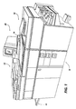
- Figure 1 schematically depicts an electrophotographic printing machine reproducing computer forms being advanced by a computer forms feeder.
- the electrophotographic printing machine, 10, is shown reproducing copies of computer forms 12.
- a document feeder, 14 is shown positioned above a platen at the imaging station of printing machine 10.
- Document feeder 14 is adapted to feed a fan-folded stack of computer forms so that individual computer forms advance, seriatim to the platen for copying.
- a stack of computer forms is fan-folded, with the web of the forms 12 passing over a guide 16 across the printing machine into document feeder 14.
- the computer web is fed by a belt in document feeder 14 to the platen.
- the computer forms are fed from the platen by the belt into output tray 18 where another stack of fan-folded forms is produced.
- Document feeder 14 will be described hereinafter in greater detail with reference to Figures 2 and 3.
- Imaging of each computer form is achieved by a flash lamp and lens (not shown).
- the flash lamp illuminates successive computer forms. Light rays reflected from the computer are transmitted through the lens.
- the lens focuses the light image of the computer form onto the charged portion of a photoconductive belt (not shown) to dissipate the charge thereon selectively. This records an electrostatic latent image on the photoconductive belt which corresponds to the informational areas contained within the computer form.
- the distance between the computer form on the platen and the photoconductive belt, as well as the position of the lens, are adjusted to set the magnification of the image. The magnification is automatically set so that the copy of the computer form fits onto the selected size copy sheet.
- the machine operator selects one of four pre-set widths corresponding to the width of the computer form, the number of holes on each incremental form, and the size of the copy sheet on a user interface 20.
- User interface 20 is a touch screen.
- the size of the copy sheet may be input automatically.
- This information is transmitted to the central processing unit of the printing machine, which unit calculates the magnification required to fit the image of the computer form onto the copy sheet.
- the central processing unit may be a microprocessor or a distributed system of microprocessors.
- the electrophotographic printing machine includes a belt having a photoconductive surface deposited on a conductive substrate.
- the belt advances successive portions of the photoconductive surface to various processing stations disposed about the path of movement thereof. Initially, a portion of the belt passes through a charging station At the charging station, a corona-generating device charges the photoconductive surface of the belt to a relatively high, substantially-uniform, potential. Thereafter, the charged portion of the photoconductive surface is advanced through the imaging station.
- a flash lamp illuminates the computer form. The light rays reflected from the computer form or original document are transmitted through the lens forming a light image thereof. These light rays are focused onto the charged portion of the photoconductive surface to dissipate the charge thereon selectively.
- the belt advances it through a development station.
- a magnetic brush development system transports a developer material of carrier granules and toner particles into contact with the electrostatic latent image.
- the toner particles are attracted from the carrier granules to the electrostatic latent image, forming a developed image or a toner powder image on the photoconductive surface of the belt.
- the belt advances the developed image to a transfer station.
- a copy sheet is moved into contact with the toner powder image.
- a coronap-generating device sprays ions onto the back of the copy sheet. This attracts the toner powder image from the photoconductive surface to the copy sheet.
- the copy sheet moves to a fusing station.
- the fusing station includes a fuser assembly which permanently affixes the transferred toner powder image to the copy sheet.
- the fuser assembly may include a heated fuser roll and a back-up roll.
- the copy sheet passes between the fuser roll and back-up roll, with the toner powder contacting the fuser roll. In this manner, the toner powder image is permanently affixed to the copy sheet.
- a conveyor belt guides the sheet to a catch tray or to a finishing station wherein a plurality of sets may be formed, with the copy sheets being either stapled or bound to one another.
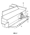
- FIG. 2 there is shown a fragmentary perspective view of document feeder 14.
- the first computer form of the fan-folded stack is placed on input tray 24, with one side edge thereof aligned against registration edge 22.
- a light-emitting diode 26 indicates that the computer form has been properly registered in the document feeder.
- An optical sensor, 28 includes a photodiode and a light-emitting diode for detecting when the lead edge of the first computer form is inserted into the document feeder
- the operator must select computer forms feeding box 40 ( Figure 5) on touch screen 20 to inform the printing machine that the document detected by sensor 28 is a computer form rather than an individual original document.
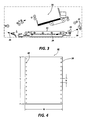
- Figure 3 depicts document feeder 14 schematically.
- the computer forms web advances in the direction of arrow 30.
- the first computer form of the web of computer forms is placed on input tray 24 and detected by optical sensor 28.
- Detector 28 transmits a signal to the central processing unit indicating the presence of a stack of fan-folded computer forms.
- the central processing unit switches the document feeder from the recirculating or single-sheet mode to the continuous forms feed mode of operation.
- Rolls 32 advance the web of computer forms in the direction of arrow 30 into the nip defined by belt 32 and platen 34.
- Belt 32 advances successive computer forms onto platen 34. After imaging each computer form, belt 34 advances the computer form in the direction of arrow 32 to output tray 18.
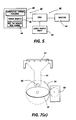
- Computer form 36 has a plurality of sprocket holes 38 in opposed side marginal regions thereof. Holes 38 are equally spaced from one another by distance D, with D being 12.7 mm.
- the length (L) of computer form 36 may be determined by multiplying the number of holes by the spacing D between adjacent holes.
- the width (W) of computer form 36 may be one of four preset widths. In the United States, these four standard widths are 378 mm, 254 mm, 241 mm, and 216 mm. In other countries, the preset widths may vary. The four preset widths are originally stored in the non-volatile memory of the central processing unit and displayed on the user interface 20 to the operator.
- the preset widths displayed may be changed by a trained machine operator.
- the operator selects the preset width corresponding to the width of computer form 36.
- the operator also counts the number of sprocket holes in one computer form 36, and inputs this information to the central processing unit.
- the central processing unit scales the input number of sprocket holes by the spacing between sprocket hole centres and adds the selected preset width to determine the semi-perimeter, i.e. length and width, of computer form 36.
- the semi-perimeter of the selected copy sheet is divided by the semi-perimeter of the computer form to determine the magnification to "best fit" the image of the computer form onto the selected copy sheet.
- the central processing unit controls the position of the platen and lens to set this magnification in the printing machine.
- the trained machine operator may define the length of the computer form (number of holes) and the preset form width as default values along with the specific copy sheet tray, i.e. size of the copy sheet. When this information is stored as default values, the operator need select only the appropriate computer forms feeding box 40 ( Figure 5) on touch screen 20 to obtain the "best fit", and will not have to make any additional selections.
- FIG. 5 is a block diagram of the system for controlling the magnification of the computer form.
- touch screen 20 includes a region which, when actuated by the operator, displays the options for computer forms.
- the computer forms option displayed on touch screen 20 includes box 40 which, when selected by the operator, transmits a signal to the central processing unit (CPU) 46 that the computer form mode of operation has been selected.
- the operator next optimally selects box 42 to input one of four widths displayed on the touch screen 20. A signal corresponding to the selected width is transmitted to the CPU.
- the operator selects box 44 to input the number of holes in the computer form to CPU 46. In this mode of operation, the CPU calculates the magnification and sets the position of the platen and lens of the imaging system.
- the first computer form may be a calibration form used to set the magnification.
- a light-emitting diode and a photodiode coupled to CPU 46 can provide an automatic count of the number of holes in the computer form.
- the photodiode transmits a pulse to the CPU for each hole in the computer form, and the CPU counts the number of pulses to determine the number of holes in the computer form.
- CPU 46 scales the number of holes by the operator-selected width and a constant, i.e., corresponding to the spacing between adjacent holes, to determine the semi-perimeter of the computer form.
- the size of the copy sheet is also input to the CPU.
- the copy sheets are placed in a tray. Different trays may hold different-sized copy sheets.
- the size of the tray determines the number of switches that are actuated when the tray is placed in the copying machine. For example, if the tray is holding copy sheets that are 216 by 279 mm, only one switch may be actuated. Alternatively, if the tray is holding copy sheets that are 81/2 inches by 14 inches, two switches may be actuated. As shown in Figure 5, the output signal from the copy paper tray is transmitted to CPU 46. CPU 46 determines the size of the selected copy sheets as a function of the combination of switches actuated by the copy paper tray. The magnification is calculated by dividing the size, i.e. semi-perimeter, of the copy sheet by the size, i.e.
- the signal from the CPU corresponding to the desired magnification controls motor 50.
- Motor 50 positions the platen and lens of the printer to set the optics at the desired magnification. In this way, the magnification is adjusted so that the image of the computer form fits on the selected size copy sheet.
- the platen 52 adapted to support the computer form during imaging is mounted on the upper housing 54.
- the upper housing is raised and lowered by two platen position cams 56.
- Cams 56 are mounted on the front and rear optics drive gears 58.
- Drive gear 60 rotates gear 58.
- Motor 50 rotates gear 60.
- Gear 60 meshes with gear 58.
- cam 56 moves upper housing 54 in a vertical direction to position platen 52 at the correct location for the calculated magnification.
- the lower housing 62 which contains the lens, is raised and lowered by two linkage arms. The linkage arms are secured to the front and rear optics drive gears 58.
- the lens also moves in a horizontal direction to maintain the image in the corner-registered position when reduction or enlargement is selected.
- the lower housing is raised for enlargement and lowered for reduction.
- Motor 50 moves both upper housing 54, which contains platen 52, and lower housing 62, which contains the lens.
- the upper housing and the lower housing are mechanically linked to the optics drive gear 58. Both of the housings move at the same time.
- the optics home sensor detects the location of the platen, via the upper housing, and sends a signal to the control logic of the central processing unit. Using the optics home sensor signal, and values entered into its non-volatile memory, the control logic determines the 100% magnification position.
- the 100% magnification position is adjustable by changing the values that are stored in the non-volatile memory of the control logic of the central processing unit.
- drive motor 50 moves the lens and platen to the home positions. Thereafter, motor 50 will rotate and each pulse will be counted. The count relative to the home position will be compared with numbers stored in the memory register of the central processing unit for the required magnification to"best fit" the image of the computer form onto the selected size copy sheet. The positive/negative aspect of the differences between the count and the stored number determines the direction of rotation of motor 50.
- Figures 7a through 7c, inclusive, show the movement of platen 52 from the 100% position to reduction and enlargement positions.
- cam follower 64 is mounted on upper housing 54 and rides on cam 56.
- Figure 7a shows the platen 52 at the 100% magnification position.
- gear 60 is rotated in the direction of arrow 66 by motor 50 to move platen 52 in the direction of arrow 68 to the reduction position.
- gear 60 is rotated in the direction of arrow 70 by motor 50 to move platen 52 in the direction of arrow 70 to the enlargement position. If platen 52 is in a reduction or enlargement position, and 100% magnification is required, then all movement occurs in the opposite direction and platen 52 is lowered.
- the printing machine of the present invention automatically adjusts the magnification of an image of a computer form to ensure that the image will fit on the copy.
- the number of sprocket holes of a unitary computer form is input into the printing machine.
- the width of the computer form may be selected from one of four preset widths and input into the printing machine.
- the size of the selected copy sheet is input into the printing machine. This information is used to calculate the required magnification to "best fit" the image of the computer form onto the selected size copy sheet.
Landscapes
- Physics & Mathematics (AREA)
- General Physics & Mathematics (AREA)
- Engineering & Computer Science (AREA)
- Microelectronics & Electronic Packaging (AREA)
- Control Or Security For Electrophotography (AREA)
- Dot-Matrix Printers And Others (AREA)
- Record Information Processing For Printing (AREA)
- Holders For Sensitive Materials And Originals (AREA)
- Exposure Or Original Feeding In Electrophotography (AREA)
Applications Claiming Priority (2)
| Application Number | Priority Date | Filing Date | Title |
|---|---|---|---|
| US414797 | 1989-09-29 | ||
| US07/414,797 US5012284A (en) | 1989-09-29 | 1989-09-29 | Magnification adjustment for computer forms |
Publications (3)
| Publication Number | Publication Date |
|---|---|
| EP0420697A2 true EP0420697A2 (de) | 1991-04-03 |
| EP0420697A3 EP0420697A3 (en) | 1992-10-14 |
| EP0420697B1 EP0420697B1 (de) | 1997-01-08 |
Family
ID=23643006
Family Applications (1)
| Application Number | Title | Priority Date | Filing Date |
|---|---|---|---|
| EP90310693A Expired - Lifetime EP0420697B1 (de) | 1989-09-29 | 1990-09-28 | Vervielfältigungsgeräte mit veränderbarer Vergrösserung |
Country Status (4)
| Country | Link |
|---|---|
| US (1) | US5012284A (de) |
| EP (1) | EP0420697B1 (de) |
| JP (1) | JP2813444B2 (de) |
| DE (1) | DE69029635T2 (de) |
Cited By (1)
| Publication number | Priority date | Publication date | Assignee | Title |
|---|---|---|---|---|
| US6414672B2 (en) * | 1997-07-07 | 2002-07-02 | Sony Corporation | Information input apparatus |
Families Citing this family (4)
| Publication number | Priority date | Publication date | Assignee | Title |
|---|---|---|---|---|
| JPH03282560A (ja) * | 1990-03-30 | 1991-12-12 | Toshiba Corp | 画像形成装置 |
| JPH05281817A (ja) * | 1992-04-02 | 1993-10-29 | Canon Inc | 画像形成装置 |
| DE19736725A1 (de) * | 1997-08-22 | 1999-02-25 | Microdat Datensysteme Gmbh | Automatisches Verfahren zur Verhinderung von Informationsverlusten an den Druckseitenrändern, insbes. bei Computerdruckern, Kopier- oder Telefaxgeräten, bei der Verarbeitung von Eingabe-Dokumenten |
| JP2007298694A (ja) * | 2006-04-28 | 2007-11-15 | Sharp Corp | 画像形成装置、設定入力表示方法、プログラムおよび記録媒体 |
Family Cites Families (13)
| Publication number | Priority date | Publication date | Assignee | Title |
|---|---|---|---|---|
| US4543643A (en) * | 1982-05-28 | 1985-09-24 | Minolta Camera | Copying magnification setting device for an electrophotographic copying apparatus |
| US4485949A (en) * | 1982-08-23 | 1984-12-04 | Xerox Corporation | Controlled frictional feeding of computer forms web |
| US4575227A (en) * | 1982-12-14 | 1986-03-11 | Minolta Camera Kabushiki Kaisha | Copying machine having a capability of reproducing images at different magnifications |
| JPS59129869A (ja) * | 1983-01-18 | 1984-07-26 | Fuji Xerox Co Ltd | 複写機の制御装置 |
| JPS60162238A (ja) * | 1984-01-31 | 1985-08-24 | Sharp Corp | 変倍複写機の倍率設定方法 |
| US4647188A (en) * | 1984-06-12 | 1987-03-03 | Canon Kabushiki Kaisha | Image forming system |
| JPH0652447B2 (ja) * | 1984-08-30 | 1994-07-06 | シャープ株式会社 | 変倍複写機 |
| US4579444A (en) * | 1984-12-06 | 1986-04-01 | Xerox Corporation | Document registration system |
| JPS61277936A (ja) * | 1985-05-31 | 1986-12-08 | Minolta Camera Co Ltd | 複写機 |
| JPS6293137A (ja) * | 1985-10-18 | 1987-04-28 | Ricoh Co Ltd | 原稿自動搬送装置付複写機 |
| GB2188618B (en) * | 1986-04-01 | 1989-11-22 | Xerox Corp | Feeding of computer fan-fold web |
| US4809050A (en) * | 1986-09-11 | 1989-02-28 | Minolta Camera Kabushiki Kaisha | Copying machine for forming an image of a document at various magnifications |
| US4745438A (en) * | 1986-09-16 | 1988-05-17 | Xerox Corporation | Automatic copier show-around erase system |
-
1989
- 1989-09-29 US US07/414,797 patent/US5012284A/en not_active Expired - Fee Related
-
1990
- 1990-09-25 JP JP2254987A patent/JP2813444B2/ja not_active Expired - Lifetime
- 1990-09-28 EP EP90310693A patent/EP0420697B1/de not_active Expired - Lifetime
- 1990-09-28 DE DE69029635T patent/DE69029635T2/de not_active Expired - Fee Related
Cited By (1)
| Publication number | Priority date | Publication date | Assignee | Title |
|---|---|---|---|---|
| US6414672B2 (en) * | 1997-07-07 | 2002-07-02 | Sony Corporation | Information input apparatus |
Also Published As
| Publication number | Publication date |
|---|---|
| JP2813444B2 (ja) | 1998-10-22 |
| DE69029635D1 (de) | 1997-02-20 |
| US5012284A (en) | 1991-04-30 |
| DE69029635T2 (de) | 1997-07-03 |
| EP0420697A3 (en) | 1992-10-14 |
| EP0420697B1 (de) | 1997-01-08 |
| JPH03150578A (ja) | 1991-06-26 |
Similar Documents
| Publication | Publication Date | Title |
|---|---|---|
| EP0113826B1 (de) | Elektronische Ausrichtung für eine Papierzufuhrvorrichtung | |
| US4602776A (en) | Insertion apparatus for use with copier/sorter system | |
| EP0293038B1 (de) | Vervielfältigungsgerät | |
| CA1247186A (en) | Sheet feeder control for reproduction machines | |
| JP4267720B2 (ja) | 複写媒体位置合わせモジュール及び電子写真プリントマシン | |
| CA1091754A (en) | Reproduction machine control | |
| CA1229368A (en) | Copy sheet tray with adjustable back stop and scuffer mechanism | |
| JPH06604B2 (ja) | コピー装置におけるシート回転装置 | |
| US5392099A (en) | Image forming apparatus having cleaning member for cleaning charging wire | |
| US6266512B1 (en) | Method of using input size determination for improvements in productivity and imaging | |
| US4792828A (en) | Image forming apparatus for forming a plurality of image from different originals on one transfer sheet | |
| CA2077325C (en) | Automatic copy sheet selection device | |
| US5374045A (en) | Printing apparatus with deferred jam clearance | |
| JP3195599B2 (ja) | 電子写真印刷機 | |
| JPH05105266A (ja) | 用紙サイズ検出装置 | |
| US5221953A (en) | Copying apparatus including a sorter with a sheet binding function | |
| EP0420697B1 (de) | Vervielfältigungsgeräte mit veränderbarer Vergrösserung | |
| US4961090A (en) | Large media proportional copying system | |
| EP0588347A1 (de) | Bilderzeugungsgerät | |
| US4824090A (en) | Automatically setting the paper path components of a reproduction machine in accordance with the size copy sheet being processed | |
| EP0282348B1 (de) | Bilderzeugungssystem mit mehreren Dokumentenregistrierpositionen | |
| EP0514179B1 (de) | Blatthandhabungsgerät | |
| CA1223288A (en) | Duplex tray system for use in copier/duplicating machine | |
| GB1594488A (en) | Sheet stacking | |
| CA1214820A (en) | Copy sheet inverter with adjustable stop mechanism |
Legal Events
| Date | Code | Title | Description |
|---|---|---|---|
| PUAI | Public reference made under article 153(3) epc to a published international application that has entered the european phase |
Free format text: ORIGINAL CODE: 0009012 |
|
| AK | Designated contracting states |
Kind code of ref document: A2 Designated state(s): DE FR GB |
|
| PUAL | Search report despatched |
Free format text: ORIGINAL CODE: 0009013 |
|
| AK | Designated contracting states |
Kind code of ref document: A3 Designated state(s): DE FR GB |
|
| 17P | Request for examination filed |
Effective date: 19930401 |
|
| 17Q | First examination report despatched |
Effective date: 19930917 |
|
| APCB | Communication from the board of appeal sent |
Free format text: ORIGINAL CODE: EPIDOS OBAPE |
|
| APCB | Communication from the board of appeal sent |
Free format text: ORIGINAL CODE: EPIDOS OBAPE |
|
| APAB | Appeal dossier modified |
Free format text: ORIGINAL CODE: EPIDOS NOAPE |
|
| GRAG | Despatch of communication of intention to grant |
Free format text: ORIGINAL CODE: EPIDOS AGRA |
|
| GRAH | Despatch of communication of intention to grant a patent |
Free format text: ORIGINAL CODE: EPIDOS IGRA |
|
| GRAH | Despatch of communication of intention to grant a patent |
Free format text: ORIGINAL CODE: EPIDOS IGRA |
|
| GRAA | (expected) grant |
Free format text: ORIGINAL CODE: 0009210 |
|
| AK | Designated contracting states |
Kind code of ref document: B1 Designated state(s): DE FR GB |
|
| REF | Corresponds to: |
Ref document number: 69029635 Country of ref document: DE Date of ref document: 19970220 |
|
| ET | Fr: translation filed | ||
| PLBE | No opposition filed within time limit |
Free format text: ORIGINAL CODE: 0009261 |
|
| STAA | Information on the status of an ep patent application or granted ep patent |
Free format text: STATUS: NO OPPOSITION FILED WITHIN TIME LIMIT |
|
| 26N | No opposition filed | ||
| PGFP | Annual fee paid to national office [announced via postgrant information from national office to epo] |
Ref country code: FR Payment date: 20010911 Year of fee payment: 12 |
|
| PGFP | Annual fee paid to national office [announced via postgrant information from national office to epo] |
Ref country code: GB Payment date: 20010926 Year of fee payment: 12 |
|
| PGFP | Annual fee paid to national office [announced via postgrant information from national office to epo] |
Ref country code: DE Payment date: 20011015 Year of fee payment: 12 |
|
| REG | Reference to a national code |
Ref country code: GB Ref legal event code: IF02 |
|
| PG25 | Lapsed in a contracting state [announced via postgrant information from national office to epo] |
Ref country code: GB Free format text: LAPSE BECAUSE OF NON-PAYMENT OF DUE FEES Effective date: 20020928 |
|
| PG25 | Lapsed in a contracting state [announced via postgrant information from national office to epo] |
Ref country code: DE Free format text: LAPSE BECAUSE OF NON-PAYMENT OF DUE FEES Effective date: 20030401 |
|
| GBPC | Gb: european patent ceased through non-payment of renewal fee |
Effective date: 20020928 |
|
| PG25 | Lapsed in a contracting state [announced via postgrant information from national office to epo] |
Ref country code: FR Free format text: LAPSE BECAUSE OF NON-PAYMENT OF DUE FEES Effective date: 20030603 |
|
| REG | Reference to a national code |
Ref country code: FR Ref legal event code: ST |
|
| APAH | Appeal reference modified |
Free format text: ORIGINAL CODE: EPIDOSCREFNO |