EP0420745B1 - Dispositif de codage d'un signal numérique - Google Patents
Dispositif de codage d'un signal numérique Download PDFInfo
- Publication number
- EP0420745B1 EP0420745B1 EP90402642A EP90402642A EP0420745B1 EP 0420745 B1 EP0420745 B1 EP 0420745B1 EP 90402642 A EP90402642 A EP 90402642A EP 90402642 A EP90402642 A EP 90402642A EP 0420745 B1 EP0420745 B1 EP 0420745B1
- Authority
- EP
- European Patent Office
- Prior art keywords
- frequency
- signals
- bands
- band
- frequency bands
- Prior art date
- Legal status (The legal status is an assumption and is not a legal conclusion. Google has not performed a legal analysis and makes no representation as to the accuracy of the status listed.)
- Expired - Lifetime
Links
Images


Classifications
-
- H—ELECTRICITY
- H03—ELECTRONIC CIRCUITRY
- H03M—CODING; DECODING; CODE CONVERSION IN GENERAL
- H03M7/00—Conversion of a code where information is represented by a given sequence or number of digits to a code where the same, similar or subset of information is represented by a different sequence or number of digits
-
- H—ELECTRICITY
- H04—ELECTRIC COMMUNICATION TECHNIQUE
- H04B—TRANSMISSION
- H04B1/00—Details of transmission systems, not covered by a single one of groups H04B3/00 - H04B13/00; Details of transmission systems not characterised by the medium used for transmission
- H04B1/66—Details of transmission systems, not covered by a single one of groups H04B3/00 - H04B13/00; Details of transmission systems not characterised by the medium used for transmission for reducing bandwidth of signals; for improving efficiency of transmission
- H04B1/667—Details of transmission systems, not covered by a single one of groups H04B3/00 - H04B13/00; Details of transmission systems not characterised by the medium used for transmission for reducing bandwidth of signals; for improving efficiency of transmission using a division in frequency subbands
-
- H—ELECTRICITY
- H04—ELECTRIC COMMUNICATION TECHNIQUE
- H04B—TRANSMISSION
- H04B1/00—Details of transmission systems, not covered by a single one of groups H04B3/00 - H04B13/00; Details of transmission systems not characterised by the medium used for transmission
- H04B1/66—Details of transmission systems, not covered by a single one of groups H04B3/00 - H04B13/00; Details of transmission systems not characterised by the medium used for transmission for reducing bandwidth of signals; for improving efficiency of transmission
- H04B1/665—Details of transmission systems, not covered by a single one of groups H04B3/00 - H04B13/00; Details of transmission systems not characterised by the medium used for transmission for reducing bandwidth of signals; for improving efficiency of transmission using psychoacoustic properties of the ear, e.g. masking effect
Definitions
- This invention relates to a digital signal encoding apparatus for encoding input digital signals.
- bit allocation As a technique of high efficiency encoding of input signals, there are known encoding techniques by so-called bit allocation, according to which input signals are divided into plural channels on the time or frequency axis and certain numbers of bits are adaptively allocated to the respective channels (bit allocation).
- SBC sub-band coding
- ATC adaptive transformation coding
- ATC-AB adaptive bit allocation
- APC-AB adaptive bit allocation
- the sub-band coding is performed by a circuit shown in Fig. 1.
- digital voice signals supplied to an input terminal 110 of an encoder 130, are fed to frequency division filters 1311 to 131 n which may for example be mirror filters, such as quadrature mirror filters (QMFs), so as to be limited in the frequency range and be shifted to lower frequency sides. That is, in these frequency division filters 1311 to 131 n , the input digital voice signals are divided into separate frequency bands by band-pass filters or BPFs and subsequently passed through low-pass filters so as to be shifted to the lower frequency sides by amounts corresponding to the center frequencies of the pass bands of the LPFs.
- QMFs quadrature mirror filters
- the signals from the filters are then supplied to quantizers 1341 to 134 n to undergo down-sampling at a suitable sampling frequency. It is noted that a higher sampling frequency should be used for a broader frequency band.
- the signals in which the data have been compressed by requantization in this manner are outputted at terminal 138 by way of a multiplexor 136.
- the output signals are then transmitted over a transmission channel to a terminal 148 of a decoder 140 and thence to dequantizers 1441 to 144 n via demultiplexor 149 for decoding.
- the decoded signals are converted by frequency converters 1421 to 142 n into signals of the frequency bands on the time axis so as to be outputted at terminal 150 as the decoded voice signals.
- quantization bits are adaptively allocated to the respective frequency bands for minimizing the effects of noises produced on data compression on voice signals to improve the quality.
- the decoder 140 also acquires the bit allocation information by some means or other to perform the decoding.
- the conventional practice for acquiring the bit allocation information has been to transmit the energy value information of each frequency band as side information in addition to the signals of the respective bands.
- the energy values of signals of the respective bands are computed at energy detection means 1331 to 133 n , from the signals divided into the frequency bands by the frequency division filters 1311 to 131 n of the encoder 130 and, based on the computed values, the optimum numbers of bit allocation and the steps of quantization at the time of quantization of the signals of the respective bands are found at an allocation-step computing unit 135.
- the results obtained at the computing unit 135 are used for requantizing the signals of the respective bands at quantizers 1341 to 134 n .
- the output signals that is the auxiliary or side information from the allocation-step computing unit 135, are transmitted to an allocation-step computing unit 145 of the decoder 140, and the data from the unit 145 are transmitted to dequantizers 1441 to 144 n , where an inverse operation of that performed at the quantizers 1341 to 134 n is performed to perform signal decoding.
- frequency division and coding noise shaping or the like may be taken into account in keeping with human auditory characteristics, and more information may be allocated to those frequency bands in which the voice energies are concentrated or which contribute more to the subjective voice quality, such as clarity.
- Signal quantization and dequantization for the respective frequency bands are performed with the allocated number of bits for reducing the extent of obstruction of hearing by the quantization noises to reduce the number of bits on the whole.
- the above mentioned frequency division and coding results in generation of quantization noises only in the frequency band concerned without affecting the remaining bands.
- the energy values of the signals of the respective bands may advantageously be employed as the quantization step widths or normalization factors of the respective frequency band signals.
- the frequency band division is usually performed in such a manner that, in order to suit the frequency analysis capability of the human auditory sense, a narrower bandwidth and a broader bandwidth are selected for the low frequency range and the high frequency range, respectively.
- the size of the analytic block for each frequency range that is the number of samples or data, will differ from one frequency range to another because of the difference in the band widths of the frequency bands, with the result that the efficiency of the analytic processing and hence the encoding efficiency are lowered.
- the constant amplitude period is thought to be longer and shorter for the low and high frequency signals, respectively, so that an efficient encoding consistent with the constant amplitude period cannot be performed.
- EP-A-0 084 125 describes apparatus for multiplexing a plurality of voice or data signals.
- the signals to be multiplexed are divided into sub-bands by a filter bank and the power level of each sub-band is measured.
- the available bit-rate of the multiplexer is shared-out adaptively to a plurality of quantisers operating on the various sub-bands, the distribution of bits to the quantisers being dependent upon the relative levels of power detected in the sub-bands.
- a digital signal encoding apparatus including means for dividing input digital signals into a plurality of frequency bands which are so set that the bands with higher frequencies will have broader bandwidths and means for synthesizing and outputting encoded signals for each of the frequency bands, characterised in that there is provided: means for detecting by spectral analysis properties of the frequency components of the frequency bands, with the period of the spectral analyses, which is the time width as a unit of the analyses along the time axis, being selected to be longer for lower frequencies, and generating a corresponding output signal; and means for controlling the synthesizing and encoding as a function of the detection output signal.
- the definition of analyses along the time axis is changed as a function of the bandwiths of the respective frequency bands to realize an optimum time interval for analyses for each frequency band.
- Fig. 1 is a block diagram showing an example of the conventional frequency division and encoding.
- Fig. 2 is a block diagram showing a first embodiment of the present invention.
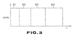
- Fig. 3 is a diagrammatic view showing the operation of the embodiment of Fig. 2.
- Fig. 4 is a block diagram showing a second embodiment of the present invention.
- Fig. 5 is a diagrammatic view for illustrating the operation of the second embodiment shown in Fig. 4 .
- Fig. 6 is a block diagram showing the filter bank of Fig. 4 in detail.
- Fig. 7 is a block diagram showing a decoder corresponding to the embodiment of Fig. 4 .
- Fig. 8 and 9 are charts for illustrating the operation of the embodiment shown in Fig. 4 .
- Fig. 2 shows diagrammatically the construction of a digital signal encoding apparatus according to a first embodiment of the present invention, wherein the frequency range is divided into four bands, as shown in Fig. 3.
- voice signals for example, are supplied as input digital signals to an input terminal 1 of the digital signal encoding apparatus.
- These voice signals are first supplied to band-pass filters (BPFs) 11 to 14.
- BPFs band-pass filters
- These BPF filters are adapted for dividing the frequency range of the voice signals into a plurality of frequency bands so that the bandwidth will become broader for the higher frequency bands so as to suit the frequency discriminating capability of the human auditory sense.
- Low-pass filters are built in the BPFs 11 to 14 so that the signals are shifted towards the low frequency sides by amounts corresponding to the central frequencies of the pass bands of the BPFs 11 to 14.
- the voice signals are divided into plural frequency bands and shifted to the lower frequency sides by the BPFs 11 to 14, are divided into frequency bands B1, B2, B3 and B4 by the BPFs 11, 12, 13 and 14, as shown in Fig. 3.
- These frequency bands B1 to B4 are selected so that the bandwidths will be the broader, the higher the frequencies, as mentioned previously.
- the signals of the respective frequency bands are quantized by quantizers 41 to 44.
- quantization the frequency characteristics of the frequency components of the respective bands are detected, and quantization is controlled as a function of the detected output. That is, with the present encoding apparatus, the numbers of allocated bits at the time of quantization are determined on the basis of the results of the signal spectral analyses for the respective frequency bands, and quantization at the quantizers 41 to 44 is performed on the basis of the so determined numbers of bit allocation.
- the signals of the respective frequency bands from the BPFs 11 to 14 are transmitted to spectrum analysis circuits 21 to 24, respectively, where spectral analyses for the respective frequency bands are performed.
- the results of the analyses are transmitted to bit allocation numbers decision circuits 31 to 34 adapted for allocating the number of the bits at the time of quantization, so that the bit allocation numbers are determined at the circuits 31 to 34 on the basis of the results of the analyses.
- Quantizations are performed at the quantizers 41 to 44 on the basis of the so determined bit allocation numbers.
- Quantization outputs of the quantizers 41 to 44 are synthesized by a multiplexor 6 so as to be outputted at an output terminal 7 of the digital signal encoding apparatus of the present embodiment.
- the block sizes of the spectral analyses that is the widths along the time axis of the analytic blocks, will differ from one frequency band to another for the same assumed precision in definition of the analyses along time axis of the frequency bands, with the result that the efficiency of spectral analyses and hence the quantization efficiency are lowered. Since it is thought in general that the constant amplitude domain of the low frequency range signal is longer and that of the high frequency range signal is shorter, an efficient coding taking such difference in the length of the constant amplitude domain cannot be realized.
- the temporal analytic accuracy that is the analytic accuracy along the time axis, is selected to be higher and lower for the high and low frequency range, respectively, for realizing a more efficient quantization.
- the durations of the spectral analyses are selected to be shorter and longer for the high and low frequency ranges, respectively.
- the period of the analyses which is the detection time interval or the time width as a unit of the analyses along the time axis, is selected to be the longer, the lower the frequency.
- Selection of the detection time intervals for spectral analyses as a function of the frequencies may be made on the basis of each of the clock signals obtained upon dividing the clock frequency of the clock signals contained in the voice signals.
- the clock signal components in the voice signals supplied to the input terminal 1 are separated in a clock separation circuit 2.
- the so separated clock signals CK are sequentially transmitted through 1/2 frequency dividers 3, 4 and 5 to produce frequency-divided clock signals (1/2) CK, divided to one half the original clock frequency CK, frequency-divided clock signals (1/4) CK, divided to one-fourth the original clock frequency CK and frequency-divided clock signals (1/8) CK, divided to one-eighth the original clock frequency CK.
- the clock signals CK are transmitted to a spectrum analysis circuit 24 and a bit allocation number decision circuit 34
- the frequency-divided clock signals (1/2) CK are transmitted to a spectrum analysis circuit 23 and a bit allocation number decision circuit 33
- the frequency-divided clock signals (1/4) CK are transmitted to a spectrum analysis circuit 22 and a bit allocation number decision circuit 32
- the frequency-divided clock signals (1/8) CK are transmitted to a spectrum analysis circuit 21 and a bit allocation number decision circuit 31.
- the detection time duration of the spectral analyses that is, the unit time width for the analyses, becomes maximum at the spectrum analysis circuit 21, while it becomes progressively shorter at the spectrum analysis circuits 22 and 23, becoming shortest at the spectrum analysis circuit 24.
- the detection time intervals for spectral analyses By changing the detection time intervals for spectral analyses in this manner, it becomes possible to realize efficient spectral analyses and hence efficient quantization at the time of quantizing the voice signals divided into a plurality of frequency bands to suit the frequency analysis capability of the human auditory sense.
- the detection time interval thus changed the spectrum for each frequency band may be thought to be constant in each block of the band, so that the values of the spectrum analyses for the long-time block may be used in the lower frequency range in substitution for the short-time spectral waveform.
- the division ratio of the frequency range need not necessarily be inversely proportionate to the time durations for spectrum analyses, that is the time durations bearing the ratios of 8:4:2:1 to the frequency of the clock signals CK.
- the relative magnitude of the division ratio is preferably selected in the above described manner. Such relative magnitude is in keeping with the direction in which the block size of the spectral analyses, that is the width of the analytic block along the time axis, may be made the same, so that the efficiency is not lowered.
- encoding is controlled in accordance with the detection output of the characteristics of the components of the frequency bands, while the detection time interval is selected to be longer for the lower frequencies, with the result that the detection efficiency is not lowered and hence efficient encoding suited to the nature of the input digital signals may be achieved.
- Fig.4 shows diagrammatically a typical construction of a high efficiency encoding apparatus for digital data according to the second embodiment.
- the high efficiency encoding apparatus for digital data is constituted by a filter bank 104, made up of mirror filters, such as quadrature mirror filters, as the frequency division filters, orthogonal transform circuits 1051 to 1055 for performing an orthogonal transform, that is a transform of the time axis into the frequency axis, such as fast Fourier transform, and a bit allocation number decision circuit 106 for determining the bit numbers allocated to the respective frequency bands.
- a filter bank 104 made up of mirror filters, such as quadrature mirror filters, as the frequency division filters, orthogonal transform circuits 1051 to 1055 for performing an orthogonal transform, that is a transform of the time axis into the frequency axis, such as fast Fourier transform, and a bit allocation number decision circuit 106 for determining the bit numbers allocated to the respective frequency bands.
- the input digital data are divided roughly into five channels, that is a channel CH1 with the frequency band of 0 to 1 kHz, a channel CH2 with the frequency band of 1 to 2 kHz, a channel CH3 with the frequency band of 2 to 4 kHz, a channel CH4 with the frequency band of 4 to 8 kHz and a channel CH5 with the frequency band of 8 to 16 kHz.
- Such frequency division in which the bandwidth becomes broader for higher frequencies is a frequency division technique taking human auditory characteristics into account, similarly to the so-called critical band.
- the critical band which takes the human auditory characteristics into account, means the band occupied by a narrow band noise masking a pure tone or sound, wherein the noise has the same amplitude as and encompassing the level or pitch of the pure tone or sound, wherein, the higher the frequency, the broader becomes the bandwidth of the critical band.
- blocks each consisting of a plurality of samples, that is a unit time block are formed by the orthogonal transform circuits 1051 to 1055 and orthogonal transform, such as a fast Fourier transform, is performed for each unit time block of each channel to produce coefficient data by the orthogonal transform, such as the FFT coefficient data for FFT.
- the coefficient data of the respective channels are transmitted to the bit allocation number decision circuit 106, where the bit allocation number data for the respective channels are formed and the coefficient data for the respective channels are quantized.
- the encoder output is outputted at an output terminal 102, while the bit allocation number data are outputted at an output terminal 103.
- the number of samples in the unit time block becomes smaller for the low frequency channels of narrower bandwidths, while becoming larger for the high frequency channels of broader bandwidths.
- the frequency resolution becomes lower and higher for the low and high frequency regions, respectively.
- the unit time block in which the orthogonal transform is performed is composed of the same number of sample data for each band or channel.
- the unit time block has different block lengths from one channel to another, in such a manner that the low range has a longer block length and the high range has a shorter block length. That is, the power of frequency resolution is maintained at a higher value for the lower frequency range while it is set so as not to be higher than is necessary for the higher frequency range and the power of temporal resolution is set to be high for the higher frequency range.
- the blocks with the same number of samples are subjected to orthogonal transform for channels CH1 to CH5, so that the same number of coefficient data, such as 64 point (pt) coefficient data, may be obtained in the respective channels.
- the channel block length is 32 ms for channel CH1, 32 ms for channel CH2, 16 ms for channel CH3, 8 ms for channel CH4 and 4 ms for channel CH5.
- the amount of processing is 64 log2 64 for channels CH1 and CH2, 64 log2 64x2 for channel CH3, 64 log2 64x4 for channel CH4 and 64 log2 64x8 for channel CH5, in the example of Fig. 5 .
- a high power of frequency resolution may be obtained at the low frequency range which is critical for the human auditory sense, while the requirement for a higher temporal resolution necessary with transient signals rich in high frequency components as shown in Fig. 8 may also be satisfied.
- the filter bank, the orthogonal transform circuits or the like may be those used conventionally so that the construction may be simplified and reduced in costs and the delay time in each circuit of the apparatus may be diminished.
- Fig. 6 shows the concrete construction of the filter bank 104.
- These input digital data are first supplied to a filter QMF 141 where the 0 to 16 kHz input digital data are divided into 0 to 8 kHz output data and 8 to 16 kHz output data, of which the 8 to 16 kHz output data are supplied to a low range conversion circuit 1455.
- the 8 to 16 kHz data undergo down-sampling in the low range conversion circuit 1455 to generate 0 to 8 kHz data, which are outputted at output terminal 1495.
- the 0 to 8 kHz output from QMF 141 is transmitted to a filter QMF 142, where it is similarly divided into a 4 to 8 kHz output transmitted to a low range conversion circuit 1454 and a 0 to 4 kHz output transmitted to a QMF 143.
- the 0 to 4 kHz data, converted into the base band data, are obtained at the low range conversion circuit 1454 so as to be outputted at output terminal 1494.
- a 0 to 2 kHz output and a 2 to 4 kHz output are produced at filter QMF 143, while a 0 to 1 kHz output and a 1 to 2 kHz output are produced at filter QMF 144, so as to be converted into low range signals in low range conversion circuits 1453 to 1451 before being outputted at output terminals 1493 to 1491.
- These outputs are transmitted via channels CH1 to CH5 to the orthogonal transform circuits 1051 to 1055, meanwhile, the low frequency conversion circuit 1451 may be omitted if so desired.
- Fig. 7 shows the construction of a decoder.
- the above mentioned encoder output is supplied to an input terminal 122, while the above mentioned bit allocation number information is supplied to an input terminal 123.
- These data are supplied to a channel information generator 126 where the data of the encoder output are restored into coefficient data of the respective channels on the basis of the bit allocation number information.
- These restored coefficient data are transmitted to inverse orthogonal conversion circuits 1251 to 1255 where an inverse operation to that in the orthogonal conversion circuits 1051 to 1055 is performed to produce data in which the frequency axis is converted into the time axis.
- the data of the respective channels on the time axis are decoded by a synthesis filter 124 before being outputted as the decoder output at output terminal 121.
- the allowable signal noise level is set and the masking effect is taken into consideration at this time so that the allowable noise level will be higher for the higher band frequency for the same energy value for determining the allocation bit number for each band.
- the masking effect means both the masking effect for signals on the time axis and that for signals on the frequency axis. That is, by such masking effect, any noise in the masked signals, if any, may not be heard.
- any noises in the masked signals on the frequency axis are allowable noises, so that, during quantization of the audio data, it becomes possible to diminish the number of the allocated bits corresponding to the allowable noise level.
- the input digital data are divided into a plurality of bands so that the bandwidth will become broader for the higher frequency range, blocks each consisting of a plurality of samples are formed for each band and orthogonal transform is performed for each of the blocks so as to produce the coefficient data to realize encoding with a higher frequency resolution power.
- the orthogonal transform block consists of the same number of sample data for each band, so that a high power of frequency resolution required for the lower frequency range may be realized, while the requirement for a high power of temporal resolution for transient signals rich in high frequency components may also be satisfied.
- the construction for implementing the encoder of the present embodiment may be simple and inexpensive since the components may be those used conventionally.
Landscapes
- Engineering & Computer Science (AREA)
- Computer Networks & Wireless Communication (AREA)
- Signal Processing (AREA)
- Theoretical Computer Science (AREA)
- Compression, Expansion, Code Conversion, And Decoders (AREA)
- Transmission Systems Not Characterized By The Medium Used For Transmission (AREA)
Claims (2)
- Appareil de codage de signaux numériques du type comportant un moyen qui sert à diviser les signaux numériques d'entrée en une pluralité de bandes de fréquence (B1 à B4) qui sont fixées de façon que les bandes associées aux fréquences supérieures (B3, B4) ont de plus grandes largeurs de bande, et un moyen (6) qui sert à synthétiser et délivrer les signaux codés pour chacune des bandes de fréquence, caractérisé en ce qu'il est prévu :
un moyen (21-24/105) servant à détecter, par analyse spectrale, les propriétés des composantes de fréquence des bandes de fréquence, la période des analyses spectrales, qui est l'intervalle de temps pris comme unité pour les analyses sur l'axe des temps, étant sélectionnée de façon à être plus longue pour les fréquences inférieures, et à produire un signal de sortie correspondant ; et
un moyen (31-34/106) servant à commander la synthèse et le codage en fonction du signal de sortie de détection. - Appareil de codage de signaux numériques selon la revendication 1, où les signaux numériques d'entrée ont un taux d'échantillonnage donné qui est déterminé par un signal d'horloge et le moyen de détection comporte un moyen (3-5) servant à extraire, du signal d'horloge d'échantillonnage, des signaux d'horloge, les fréquences respectives de ces signaux d'horloge utilisées dans l'analyse spectrale étant sélectionnées de façon à être inférieures pour les bandes de fréquences inférieures.
Applications Claiming Priority (4)
| Application Number | Priority Date | Filing Date | Title |
|---|---|---|---|
| JP1249835A JP2906477B2 (ja) | 1989-09-26 | 1989-09-26 | ディジタル信号符号化方法 |
| JP249835/89 | 1989-09-26 | ||
| JP278207/89 | 1989-10-25 | ||
| JP1278207A JP2906483B2 (ja) | 1989-10-25 | 1989-10-25 | ディジタル音声データの高能率符号化方法及びディジタル音声データの復号化装置 |
Publications (3)
| Publication Number | Publication Date |
|---|---|
| EP0420745A2 EP0420745A2 (fr) | 1991-04-03 |
| EP0420745A3 EP0420745A3 (en) | 1992-08-19 |
| EP0420745B1 true EP0420745B1 (fr) | 1995-11-15 |
Family
ID=26539517
Family Applications (1)
| Application Number | Title | Priority Date | Filing Date |
|---|---|---|---|
| EP90402642A Expired - Lifetime EP0420745B1 (fr) | 1989-09-26 | 1990-09-25 | Dispositif de codage d'un signal numérique |
Country Status (4)
| Country | Link |
|---|---|
| US (2) | US5115240A (fr) |
| EP (1) | EP0420745B1 (fr) |
| KR (1) | KR100242864B1 (fr) |
| DE (1) | DE69023604T2 (fr) |
Families Citing this family (81)
| Publication number | Priority date | Publication date | Assignee | Title |
|---|---|---|---|---|
| US5230038A (en) * | 1989-01-27 | 1993-07-20 | Fielder Louis D | Low bit rate transform coder, decoder, and encoder/decoder for high-quality audio |
| US5222189A (en) * | 1989-01-27 | 1993-06-22 | Dolby Laboratories Licensing Corporation | Low time-delay transform coder, decoder, and encoder/decoder for high-quality audio |
| US5752225A (en) * | 1989-01-27 | 1998-05-12 | Dolby Laboratories Licensing Corporation | Method and apparatus for split-band encoding and split-band decoding of audio information using adaptive bit allocation to adjacent subbands |
| US5502789A (en) * | 1990-03-07 | 1996-03-26 | Sony Corporation | Apparatus for encoding digital data with reduction of perceptible noise |
| CN1062963C (zh) * | 1990-04-12 | 2001-03-07 | 多尔拜实验特许公司 | 用于产生高质量声音信号的解码器和编码器 |
| US5388181A (en) * | 1990-05-29 | 1995-02-07 | Anderson; David J. | Digital audio compression system |
| US5365553A (en) * | 1990-11-30 | 1994-11-15 | U.S. Philips Corporation | Transmitter, encoding system and method employing use of a bit need determiner for subband coding a digital signal |
| JP3158458B2 (ja) * | 1991-01-31 | 2001-04-23 | 日本電気株式会社 | 階層表現された信号の符号化方式 |
| ZA921988B (en) * | 1991-03-29 | 1993-02-24 | Sony Corp | High efficiency digital data encoding and decoding apparatus |
| JP3134337B2 (ja) * | 1991-03-30 | 2001-02-13 | ソニー株式会社 | ディジタル信号符号化方法 |
| JP3134338B2 (ja) * | 1991-03-30 | 2001-02-13 | ソニー株式会社 | ディジタル音声信号符号化方法 |
| GB2257606B (en) * | 1991-06-28 | 1995-01-18 | Sony Corp | Recording and/or reproducing apparatuses and signal processing methods for compressed data |
| DE4124493C1 (fr) * | 1991-07-24 | 1993-02-11 | Institut Fuer Rundfunktechnik Gmbh, 8000 Muenchen, De | |
| ES2164640T3 (es) * | 1991-08-02 | 2002-03-01 | Sony Corp | Codificador digital con asignacion dinamica de bits de cuantificacion. |
| US5388209A (en) * | 1991-08-02 | 1995-02-07 | Sony Corporation | Apparatus for high-speed recording compressed digital data with increased compression |
| JP3178026B2 (ja) * | 1991-08-23 | 2001-06-18 | ソニー株式会社 | ディジタル信号符号化装置及び復号化装置 |
| DE69231369T2 (de) * | 1991-09-30 | 2001-03-29 | Sony Corp., Tokio/Tokyo | Verfahren und Einrichtung zur Audiodatenkompression |
| JP3141450B2 (ja) * | 1991-09-30 | 2001-03-05 | ソニー株式会社 | オーディオ信号処理方法 |
| JP3134455B2 (ja) * | 1992-01-29 | 2001-02-13 | ソニー株式会社 | 高能率符号化装置及び方法 |
| US5765127A (en) * | 1992-03-18 | 1998-06-09 | Sony Corp | High efficiency encoding method |
| JP3104400B2 (ja) * | 1992-04-27 | 2000-10-30 | ソニー株式会社 | オーディオ信号符号化装置及び方法 |
| US5304994A (en) * | 1992-06-09 | 1994-04-19 | Hewlett Packard Company | Minimal delay leading one detector with result bias control |
| JP3153933B2 (ja) * | 1992-06-16 | 2001-04-09 | ソニー株式会社 | データ符号化装置及び方法並びにデータ復号化装置及び方法 |
| JP3233234B2 (ja) * | 1992-09-07 | 2001-11-26 | ソニー株式会社 | ディスク記録装置 |
| JP3508146B2 (ja) * | 1992-09-11 | 2004-03-22 | ソニー株式会社 | ディジタル信号符号化復号化装置、ディジタル信号符号化装置及びディジタル信号復号化装置 |
| JP3127600B2 (ja) * | 1992-09-11 | 2001-01-29 | ソニー株式会社 | ディジタル信号復号化装置及び方法 |
| JP3343962B2 (ja) * | 1992-11-11 | 2002-11-11 | ソニー株式会社 | 高能率符号化方法及び装置 |
| JP3185413B2 (ja) * | 1992-11-25 | 2001-07-09 | ソニー株式会社 | 直交変換演算並びに逆直交変換演算方法及びその装置、ディジタル信号符号化及び/又は復号化装置 |
| JPH06202285A (ja) * | 1992-12-28 | 1994-07-22 | Sony Corp | 映写フィルム |
| JP3123286B2 (ja) * | 1993-02-18 | 2001-01-09 | ソニー株式会社 | ディジタル信号処理装置又は方法、及び記録媒体 |
| JP3186292B2 (ja) * | 1993-02-02 | 2001-07-11 | ソニー株式会社 | 高能率符号化方法及び装置 |
| US5392044A (en) * | 1993-03-08 | 1995-02-21 | Motorola, Inc. | Method and apparatus for digitizing a wide frequency bandwidth signal |
| JP3123290B2 (ja) * | 1993-03-09 | 2001-01-09 | ソニー株式会社 | 圧縮データ記録装置及び方法、圧縮データ再生方法、記録媒体 |
| TW232116B (en) * | 1993-04-14 | 1994-10-11 | Sony Corp | Method or device and recording media for signal conversion |
| JP3173218B2 (ja) * | 1993-05-10 | 2001-06-04 | ソニー株式会社 | 圧縮データ記録方法及び装置、圧縮データ再生方法、並びに記録媒体 |
| CA2140779C (fr) * | 1993-05-31 | 2005-09-20 | Kyoya Tsutsui | Methode, appareil et support d'enregistrement pour le codage de tonalite separee et des composantes spectrales des caracteristiques du bruit d'un signal acoustique |
| AU682032B2 (en) * | 1993-06-29 | 1997-09-18 | Sony Corporation | Audio signal transmitting apparatus and the method thereof |
| PL173718B1 (pl) * | 1993-06-30 | 1998-04-30 | Sony Corp | Sposób i urządzenie do kodowania sygnałów cyfrowych |
| TW272341B (fr) * | 1993-07-16 | 1996-03-11 | Sony Co Ltd | |
| TW327223B (en) * | 1993-09-28 | 1998-02-21 | Sony Co Ltd | Methods and apparatus for encoding an input signal broken into frequency components, methods and apparatus for decoding such encoded signal |
| US5737720A (en) * | 1993-10-26 | 1998-04-07 | Sony Corporation | Low bit rate multichannel audio coding methods and apparatus using non-linear adaptive bit allocation |
| WO1995012920A1 (fr) * | 1993-11-04 | 1995-05-11 | Sony Corporation | Codeur de signaux, decodeur de signaux, support d'enregistrement et procede de codage de signaux |
| EP0692881B1 (fr) * | 1993-11-09 | 2005-06-15 | Sony Corporation | Appareil de quantification, procede de quantification, codeur a haute efficacite, procede de codage a haute efficacite, decodeur, supports d'enregistrement et de codage a haute efficacite |
| US5608713A (en) * | 1994-02-09 | 1997-03-04 | Sony Corporation | Bit allocation of digital audio signal blocks by non-linear processing |
| DE4405659C1 (de) * | 1994-02-22 | 1995-04-06 | Fraunhofer Ges Forschung | Verfahren zum kaskadierten Codieren und Decodieren von Audiodaten |
| JP3186412B2 (ja) * | 1994-04-01 | 2001-07-11 | ソニー株式会社 | 情報符号化方法、情報復号化方法、及び情報伝送方法 |
| JP3277682B2 (ja) * | 1994-04-22 | 2002-04-22 | ソニー株式会社 | 情報符号化方法及び装置、情報復号化方法及び装置、並びに情報記録媒体及び情報伝送方法 |
| TW295747B (fr) * | 1994-06-13 | 1997-01-11 | Sony Co Ltd | |
| JP3250376B2 (ja) * | 1994-06-13 | 2002-01-28 | ソニー株式会社 | 情報符号化方法及び装置並びに情報復号化方法及び装置 |
| JP3277705B2 (ja) | 1994-07-27 | 2002-04-22 | ソニー株式会社 | 情報符号化装置及び方法、並びに情報復号化装置及び方法 |
| JP3341474B2 (ja) * | 1994-07-28 | 2002-11-05 | ソニー株式会社 | 情報符号化方法及び復号化方法、情報符号化装置及び復号化装置、並びに情報記録媒体 |
| US5893065A (en) * | 1994-08-05 | 1999-04-06 | Nippon Steel Corporation | Apparatus for compressing audio data |
| JP3536996B2 (ja) * | 1994-09-13 | 2004-06-14 | ソニー株式会社 | パラメータ変換方法及び音声合成方法 |
| US5926791A (en) * | 1995-10-26 | 1999-07-20 | Sony Corporation | Recursively splitting the low-frequency band with successively fewer filter taps in methods and apparatuses for sub-band encoding, decoding, and encoding and decoding |
| US5956674A (en) * | 1995-12-01 | 1999-09-21 | Digital Theater Systems, Inc. | Multi-channel predictive subband audio coder using psychoacoustic adaptive bit allocation in frequency, time and over the multiple channels |
| US5822370A (en) * | 1996-04-16 | 1998-10-13 | Aura Systems, Inc. | Compression/decompression for preservation of high fidelity speech quality at low bandwidth |
| US5848391A (en) * | 1996-07-11 | 1998-12-08 | Fraunhofer-Gesellschaft Zur Forderung Der Angewandten Forschung E.V. | Method subband of coding and decoding audio signals using variable length windows |
| JP3318825B2 (ja) * | 1996-08-20 | 2002-08-26 | ソニー株式会社 | デジタル信号符号化処理方法、デジタル信号符号化処理装置、デジタル信号記録方法、デジタル信号記録装置、記録媒体、デジタル信号伝送方法及びデジタル信号伝送装置 |
| JPH1084284A (ja) * | 1996-09-06 | 1998-03-31 | Sony Corp | 信号再生方法および装置 |
| JP4121578B2 (ja) * | 1996-10-18 | 2008-07-23 | ソニー株式会社 | 音声分析方法、音声符号化方法および装置 |
| JP3496411B2 (ja) * | 1996-10-30 | 2004-02-09 | ソニー株式会社 | 情報符号化方法及び復号化装置 |
| FI114248B (fi) * | 1997-03-14 | 2004-09-15 | Nokia Corp | Menetelmä ja laite audiokoodaukseen ja audiodekoodaukseen |
| US6476735B2 (en) * | 2000-12-02 | 2002-11-05 | Daniel David Lang | Method of encoding bits using a plurality of frequencies |
| GB0108080D0 (en) * | 2001-03-30 | 2001-05-23 | Univ Bath | Audio compression |
| JP2003110429A (ja) * | 2001-09-28 | 2003-04-11 | Sony Corp | 符号化方法及び装置、復号方法及び装置、伝送方法及び装置、並びに記録媒体 |
| US7240001B2 (en) * | 2001-12-14 | 2007-07-03 | Microsoft Corporation | Quality improvement techniques in an audio encoder |
| US6934677B2 (en) * | 2001-12-14 | 2005-08-23 | Microsoft Corporation | Quantization matrices based on critical band pattern information for digital audio wherein quantization bands differ from critical bands |
| US7502743B2 (en) | 2002-09-04 | 2009-03-10 | Microsoft Corporation | Multi-channel audio encoding and decoding with multi-channel transform selection |
| JP4676140B2 (ja) | 2002-09-04 | 2011-04-27 | マイクロソフト コーポレーション | オーディオの量子化および逆量子化 |
| JP4657570B2 (ja) * | 2002-11-13 | 2011-03-23 | ソニー株式会社 | 音楽情報符号化装置及び方法、音楽情報復号装置及び方法、並びにプログラム及び記録媒体 |
| US7460990B2 (en) * | 2004-01-23 | 2008-12-02 | Microsoft Corporation | Efficient coding of digital media spectral data using wide-sense perceptual similarity |
| US9530425B2 (en) | 2005-02-23 | 2016-12-27 | Vios Medical Singapore Pte. Ltd. | Method and apparatus for signal decomposition, analysis, reconstruction and tracking |
| WO2006091636A2 (fr) | 2005-02-23 | 2006-08-31 | Digital Intelligence, L.L.C. | Systeme et procede de decomposition, d'analyse et de reconstruction d'un signal |
| US7885819B2 (en) | 2007-06-29 | 2011-02-08 | Microsoft Corporation | Bitstream syntax for multi-process audio decoding |
| US8249883B2 (en) * | 2007-10-26 | 2012-08-21 | Microsoft Corporation | Channel extension coding for multi-channel source |
| DE102008015435B4 (de) * | 2008-03-22 | 2010-05-27 | Fette Gmbh | Konusrändelwerkzeug |
| US8666753B2 (en) | 2011-12-12 | 2014-03-04 | Motorola Mobility Llc | Apparatus and method for audio encoding |
| US11602311B2 (en) | 2019-01-29 | 2023-03-14 | Murata Vios, Inc. | Pulse oximetry system |
| CN110111800B (zh) * | 2019-04-04 | 2021-05-07 | 深圳信息职业技术学院 | 一种电子耳蜗的频带划分方法、装置及电子耳蜗设备 |
| US11778401B2 (en) | 2020-03-19 | 2023-10-03 | Lisnr, Inc | Channel-based control of audio transmissions |
| US11095999B1 (en) * | 2020-03-19 | 2021-08-17 | Lisnr | Channel-based control of audio transmissions |
Family Cites Families (51)
| Publication number | Priority date | Publication date | Assignee | Title |
|---|---|---|---|---|
| US3349183A (en) * | 1963-10-29 | 1967-10-24 | Melpar Inc | Speech compression system transmitting only coefficients of polynomial representations of phonemes |
| US4184049A (en) * | 1978-08-25 | 1980-01-15 | Bell Telephone Laboratories, Incorporated | Transform speech signal coding with pitch controlled adaptive quantizing |
| JPS55125511A (en) * | 1979-03-20 | 1980-09-27 | Olympus Optical Co Ltd | Method and device for channel division recording and reproduction |
| CH645501GA3 (fr) * | 1981-07-24 | 1984-10-15 | ||
| US4455649A (en) * | 1982-01-15 | 1984-06-19 | International Business Machines Corporation | Method and apparatus for efficient statistical multiplexing of voice and data signals |
| US4625286A (en) * | 1982-05-03 | 1986-11-25 | Texas Instruments Incorporated | Time encoding of LPC roots |
| US4535472A (en) * | 1982-11-05 | 1985-08-13 | At&T Bell Laboratories | Adaptive bit allocator |
| JPH07118159B2 (ja) * | 1982-12-06 | 1995-12-18 | ソニー株式会社 | Pcm信号記録方法 |
| DE3314384A1 (de) * | 1983-04-21 | 1984-10-25 | Siemens AG, 1000 Berlin und 8000 München | Uebertragungssystem |
| JPH07118160B2 (ja) * | 1983-06-18 | 1995-12-18 | ソニー株式会社 | ディジタル情報信号の記録方法 |
| US4516241A (en) * | 1983-07-11 | 1985-05-07 | At&T Bell Laboratories | Bit compression coding with embedded signaling |
| GB8421498D0 (en) * | 1984-08-24 | 1984-09-26 | British Telecomm | Frequency domain speech coding |
| JPS61107818A (ja) * | 1984-10-30 | 1986-05-26 | Nec Corp | エントロピ−符号化方式とその装置 |
| US4885790A (en) * | 1985-03-18 | 1989-12-05 | Massachusetts Institute Of Technology | Processing of acoustic waveforms |
| US4748579A (en) * | 1985-08-14 | 1988-05-31 | Gte Laboratories Incorporated | Method and circuit for performing discrete transforms |
| DE3688980T2 (de) * | 1986-10-30 | 1994-04-21 | Ibm | Verfahren zur Multigeschwindigkeitskodierung von Signalen und Einrichtung zur Durchführung dieses Verfahrens. |
| US4851906A (en) * | 1986-11-04 | 1989-07-25 | Nec Corporation | Data compression using orthogonal transform and vector quantization |
| AU604807B2 (en) * | 1986-12-19 | 1991-01-03 | Sony Corporation | Data recorder and method |
| US4903301A (en) * | 1987-02-27 | 1990-02-20 | Hitachi, Ltd. | Method and system for transmitting variable rate speech signal |
| NL8700985A (nl) * | 1987-04-27 | 1988-11-16 | Philips Nv | Systeem voor sub-band codering van een digitaal audiosignaal. |
| US4882754A (en) * | 1987-08-25 | 1989-11-21 | Digideck, Inc. | Data compression system and method with buffer control |
| JPH0213135A (ja) * | 1988-06-30 | 1990-01-17 | Sony Corp | ディジタル信号伝送装置 |
| JPH0783315B2 (ja) * | 1988-09-26 | 1995-09-06 | 富士通株式会社 | 可変レート音声信号符号化方式 |
| US5384891A (en) * | 1988-09-28 | 1995-01-24 | Hitachi, Ltd. | Vector quantizing apparatus and speech analysis-synthesis system using the apparatus |
| US5222189A (en) * | 1989-01-27 | 1993-06-22 | Dolby Laboratories Licensing Corporation | Low time-delay transform coder, decoder, and encoder/decoder for high-quality audio |
| SG82549A1 (en) * | 1989-01-27 | 2001-08-21 | Dolby Lab Licensing Corp | Coded signal formatting for encoder and decoder of high-quality audio |
| US5016107A (en) * | 1989-05-09 | 1991-05-14 | Eastman Kodak Company | Electronic still camera utilizing image compression and digital storage |
| US4932062A (en) * | 1989-05-15 | 1990-06-05 | Dialogic Corporation | Method and apparatus for frequency analysis of telephone signals |
| DE3925937A1 (de) * | 1989-08-03 | 1991-02-14 | Mannesmann Ag | Motorischer antrieb mit einem mehrgaengigen getriebe fuer eine aussenhuelse |
| FR2653280B1 (fr) * | 1989-10-13 | 1992-01-10 | France Etat | Dispositif d'allocation de bits pour signal audio-numerique transforme, a quantification adaptative sur critere psycho-auditif. |
| US5040217A (en) * | 1989-10-18 | 1991-08-13 | At&T Bell Laboratories | Perceptual coding of audio signals |
| CA2032765C (fr) * | 1989-12-21 | 1995-12-12 | Hidetaka Yoshikawa | Appareil de communication a vitesse de codage variable |
| JP2913731B2 (ja) * | 1990-03-07 | 1999-06-28 | ソニー株式会社 | ディジタルデータの高能率符号化方法 |
| CN1062963C (zh) * | 1990-04-12 | 2001-03-07 | 多尔拜实验特许公司 | 用于产生高质量声音信号的解码器和编码器 |
| JP2751564B2 (ja) * | 1990-05-25 | 1998-05-18 | ソニー株式会社 | ディジタル信号符号化装置 |
| JP3185214B2 (ja) * | 1990-06-12 | 2001-07-09 | 日本電気株式会社 | 改良dctの順変換計算装置および逆変換計算装置 |
| JPH0472909A (ja) * | 1990-07-13 | 1992-03-06 | Sony Corp | オーディオ信号の量子化誤差低減装置 |
| JP3141241B2 (ja) * | 1990-08-24 | 2001-03-05 | ソニー株式会社 | ディスク記録装置及びディスク再生装置 |
| JP3033156B2 (ja) * | 1990-08-24 | 2000-04-17 | ソニー株式会社 | ディジタル信号符号化装置 |
| ZA921988B (en) * | 1991-03-29 | 1993-02-24 | Sony Corp | High efficiency digital data encoding and decoding apparatus |
| EP0506394A2 (fr) * | 1991-03-29 | 1992-09-30 | Sony Corporation | Dispositif pour le codage de signaux digitaux |
| EP0531538B1 (fr) * | 1991-03-29 | 1998-04-15 | Sony Corporation | Reduction de la taille d'information de formatage pour codage par sous-bandes |
| JP3134337B2 (ja) * | 1991-03-30 | 2001-02-13 | ソニー株式会社 | ディジタル信号符号化方法 |
| JP3134338B2 (ja) * | 1991-03-30 | 2001-02-13 | ソニー株式会社 | ディジタル音声信号符号化方法 |
| US5388209A (en) * | 1991-08-02 | 1995-02-07 | Sony Corporation | Apparatus for high-speed recording compressed digital data with increased compression |
| JP3178026B2 (ja) * | 1991-08-23 | 2001-06-18 | ソニー株式会社 | ディジタル信号符号化装置及び復号化装置 |
| JP3198550B2 (ja) * | 1991-09-03 | 2001-08-13 | ソニー株式会社 | 圧縮データ記録方法及び圧縮データ記録再生装置 |
| JP3158556B2 (ja) * | 1991-09-27 | 2001-04-23 | ソニー株式会社 | ディスク記録装置及びディスク再生装置 |
| JP3141450B2 (ja) * | 1991-09-30 | 2001-03-05 | ソニー株式会社 | オーディオ信号処理方法 |
| JP3508146B2 (ja) * | 1992-09-11 | 2004-03-22 | ソニー株式会社 | ディジタル信号符号化復号化装置、ディジタル信号符号化装置及びディジタル信号復号化装置 |
| JP3127600B2 (ja) * | 1992-09-11 | 2001-01-29 | ソニー株式会社 | ディジタル信号復号化装置及び方法 |
-
1990
- 1990-09-21 US US07/586,494 patent/US5115240A/en not_active Ceased
- 1990-09-25 EP EP90402642A patent/EP0420745B1/fr not_active Expired - Lifetime
- 1990-09-25 DE DE69023604T patent/DE69023604T2/de not_active Expired - Lifetime
- 1990-09-26 KR KR1019900015234A patent/KR100242864B1/ko not_active Expired - Lifetime
-
1994
- 1994-05-18 US US08/245,451 patent/USRE36559E/en not_active Expired - Lifetime
Also Published As
| Publication number | Publication date |
|---|---|
| DE69023604T2 (de) | 1996-04-18 |
| KR100242864B1 (ko) | 2000-02-01 |
| US5115240A (en) | 1992-05-19 |
| EP0420745A2 (fr) | 1991-04-03 |
| USRE36559E (en) | 2000-02-08 |
| KR910007293A (ko) | 1991-04-30 |
| EP0420745A3 (en) | 1992-08-19 |
| DE69023604D1 (de) | 1995-12-21 |
Similar Documents
| Publication | Publication Date | Title |
|---|---|---|
| US5115240A (en) | Method and apparatus for encoding voice signals divided into a plurality of frequency bands | |
| US4972484A (en) | Method of transmitting or storing masked sub-band coded audio signals | |
| EP0537361B1 (fr) | Appareil de codage et de decodage de donnees numeriques a haut niveau d'efficacite | |
| US5664056A (en) | Digital encoder with dynamic quantization bit allocation | |
| EP0709004B1 (fr) | Systeme d'attribution hybride et adaptatif pour un codeur et decodeur audio | |
| KR100221892B1 (ko) | 디지탈 신호 인코더 | |
| KR100419546B1 (ko) | 신호부호화방법및장치,신호복호화방법및장치,및신호전송방법 | |
| JP3277692B2 (ja) | 情報符号化方法、情報復号化方法及び情報記録媒体 | |
| Crochiere | On the Design of Sub‐band Coders for Low‐Bit‐Rate Speech Communication | |
| KR100295217B1 (ko) | 신호스펙트럼-의존양자화비트할당및노이즈스펙트럼-의존양자화비트할당으로서디지탈입력신호를압축하는장치 | |
| US5581654A (en) | Method and apparatus for information encoding and decoding | |
| JPS6161305B2 (fr) | ||
| HU215685B (hu) | Eljárás és berendezés széles sávú digitális adatjelek kódolására és dekódolására | |
| US5781586A (en) | Method and apparatus for encoding the information, method and apparatus for decoding the information and information recording medium | |
| JP3277699B2 (ja) | 信号符号化方法及び装置並びに信号復号化方法及び装置 | |
| EP0398973B1 (fr) | Procede et appareil de codage de signaux electriques | |
| EP0709981B1 (fr) | Codage de signaux en sous-bandes avec codage prédictif basé sur la hauteur du ton dans chaque sous-bande | |
| KR100351772B1 (ko) | 디지털부호화장치,디지털기록신호도출장치및디지털신호데이터도출방법 | |
| KR0152016B1 (ko) | 가변 비트할당을 이용한 부호화 및 복호화시스템 | |
| KR0134350B1 (ko) | 적응적 비트할당을 이용한 부호화 및 복호화시스템 | |
| JP3134384B2 (ja) | 符号化装置及び方法 | |
| KR100340368B1 (ko) | 고능률부호화장치,복호화장치및디지털데이터도출방법 | |
| JP2906477B2 (ja) | ディジタル信号符号化方法 | |
| KR0124384B1 (ko) | 오디어 방송종류에 따른 가변비트 할당장치 | |
| JPH0744192A (ja) | 情報符号化又は情報復号化方法、並びに記録媒体 |
Legal Events
| Date | Code | Title | Description |
|---|---|---|---|
| PUAI | Public reference made under article 153(3) epc to a published international application that has entered the european phase |
Free format text: ORIGINAL CODE: 0009012 |
|
| AK | Designated contracting states |
Kind code of ref document: A2 Designated state(s): DE FR GB |
|
| PUAL | Search report despatched |
Free format text: ORIGINAL CODE: 0009013 |
|
| AK | Designated contracting states |
Kind code of ref document: A3 Designated state(s): DE FR GB |
|
| 17P | Request for examination filed |
Effective date: 19930123 |
|
| 17Q | First examination report despatched |
Effective date: 19940510 |
|
| GRAA | (expected) grant |
Free format text: ORIGINAL CODE: 0009210 |
|
| AK | Designated contracting states |
Kind code of ref document: B1 Designated state(s): DE FR GB |
|
| REF | Corresponds to: |
Ref document number: 69023604 Country of ref document: DE Date of ref document: 19951221 |
|
| ET | Fr: translation filed | ||
| PLBE | No opposition filed within time limit |
Free format text: ORIGINAL CODE: 0009261 |
|
| STAA | Information on the status of an ep patent application or granted ep patent |
Free format text: STATUS: NO OPPOSITION FILED WITHIN TIME LIMIT |
|
| 26N | No opposition filed | ||
| REG | Reference to a national code |
Ref country code: GB Ref legal event code: IF02 |
|
| PGFP | Annual fee paid to national office [announced via postgrant information from national office to epo] |
Ref country code: GB Payment date: 20090923 Year of fee payment: 20 |
|
| PGFP | Annual fee paid to national office [announced via postgrant information from national office to epo] |
Ref country code: DE Payment date: 20090917 Year of fee payment: 20 |
|
| PGFP | Annual fee paid to national office [announced via postgrant information from national office to epo] |
Ref country code: FR Payment date: 20091012 Year of fee payment: 20 |
|
| REG | Reference to a national code |
Ref country code: GB Ref legal event code: PE20 Expiry date: 20100924 |
|
| PG25 | Lapsed in a contracting state [announced via postgrant information from national office to epo] |
Ref country code: GB Free format text: LAPSE BECAUSE OF EXPIRATION OF PROTECTION Effective date: 20100924 |
|
| PG25 | Lapsed in a contracting state [announced via postgrant information from national office to epo] |
Ref country code: DE Free format text: LAPSE BECAUSE OF EXPIRATION OF PROTECTION Effective date: 20100925 |