EP0420824A1 - Eine Rückenlehne für einen Sitz, insbesondere einen Kraftfahrzeugsitz - Google Patents
Eine Rückenlehne für einen Sitz, insbesondere einen Kraftfahrzeugsitz Download PDFInfo
- Publication number
- EP0420824A1 EP0420824A1 EP90830404A EP90830404A EP0420824A1 EP 0420824 A1 EP0420824 A1 EP 0420824A1 EP 90830404 A EP90830404 A EP 90830404A EP 90830404 A EP90830404 A EP 90830404A EP 0420824 A1 EP0420824 A1 EP 0420824A1
- Authority
- EP
- European Patent Office
- Prior art keywords
- parts
- backrest according
- strip member
- frame
- backrest
- Prior art date
- Legal status (The legal status is an assumption and is not a legal conclusion. Google has not performed a legal analysis and makes no representation as to the accuracy of the status listed.)
- Granted
Links
- 244000261422 Lysimachia clethroides Species 0.000 claims description 3
- 230000006835 compression Effects 0.000 claims description 2
- 238000007906 compression Methods 0.000 claims description 2
- 230000000694 effects Effects 0.000 claims 1
- 239000000463 material Substances 0.000 description 5
- 230000000875 corresponding effect Effects 0.000 description 3
- 210000004705 lumbosacral region Anatomy 0.000 description 3
- 239000002184 metal Substances 0.000 description 3
- 229910052751 metal Inorganic materials 0.000 description 3
- XEEYBQQBJWHFJM-UHFFFAOYSA-N Iron Chemical compound [Fe] XEEYBQQBJWHFJM-UHFFFAOYSA-N 0.000 description 2
- 230000001133 acceleration Effects 0.000 description 2
- 230000009977 dual effect Effects 0.000 description 2
- 210000004197 pelvis Anatomy 0.000 description 2
- 229920005830 Polyurethane Foam Polymers 0.000 description 1
- 210000003484 anatomy Anatomy 0.000 description 1
- 230000015572 biosynthetic process Effects 0.000 description 1
- 210000001217 buttock Anatomy 0.000 description 1
- 229920001971 elastomer Polymers 0.000 description 1
- 239000004744 fabric Substances 0.000 description 1
- 230000002349 favourable effect Effects 0.000 description 1
- 238000005755 formation reaction Methods 0.000 description 1
- 210000001624 hip Anatomy 0.000 description 1
- 238000003780 insertion Methods 0.000 description 1
- 230000037431 insertion Effects 0.000 description 1
- 229910052742 iron Inorganic materials 0.000 description 1
- 239000010985 leather Substances 0.000 description 1
- 239000002649 leather substitute Substances 0.000 description 1
- 230000014759 maintenance of location Effects 0.000 description 1
- 239000004033 plastic Substances 0.000 description 1
- 229920003023 plastic Polymers 0.000 description 1
- 239000011496 polyurethane foam Substances 0.000 description 1
- 239000012858 resilient material Substances 0.000 description 1
- 210000000954 sacrococcygeal region Anatomy 0.000 description 1
- 150000003839 salts Chemical class 0.000 description 1
- 238000000926 separation method Methods 0.000 description 1
- 210000001364 upper extremity Anatomy 0.000 description 1
Images






Classifications
-
- B—PERFORMING OPERATIONS; TRANSPORTING
- B60—VEHICLES IN GENERAL
- B60N—SEATS SPECIALLY ADAPTED FOR VEHICLES; VEHICLE PASSENGER ACCOMMODATION NOT OTHERWISE PROVIDED FOR
- B60N2/00—Seats specially adapted for vehicles; Arrangement or mounting of seats in vehicles
- B60N2/64—Back-rests or cushions
- B60N2/66—Lumbar supports
- B60N2/667—Lumbar supports having flexible support member bowed by applied forces
-
- B—PERFORMING OPERATIONS; TRANSPORTING
- B60—VEHICLES IN GENERAL
- B60N—SEATS SPECIALLY ADAPTED FOR VEHICLES; VEHICLE PASSENGER ACCOMMODATION NOT OTHERWISE PROVIDED FOR
- B60N2/00—Seats specially adapted for vehicles; Arrangement or mounting of seats in vehicles
- B60N2/64—Back-rests or cushions
- B60N2/66—Lumbar supports
Definitions
- the present invention relates to backrests for seats and has been developed with particular attention to its possible use in the field of motor-car seats.
- the objects of the present invention is to provide a backrest which can provide lumbar support over a wide, wrap-around surface area and with the added possibility that the transverse restraint provided by the backrest can adapt automatically to fit different human frames.
- a lumbar support with very high side portions for achieving effective transverse restraint in a seat such as a motor-car seat complies with precise information regarding functional anatomy.
- the present invention therefore proposes the use of a butterfly- (or hourglass-) shaped lumbar support, that is a support whose central portion is not very deep but whose side wings are much deeper.
- the object of the invention is achieved even better by the use of a lumbar support system which can articulate spontaneously as a result of the pressure exerted by the backs of the various users of the seat whose backs have widely differing radii of curvature.
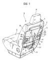
- a motor-car seat is generally indicated S and includes a salt or, in short, a "squab" C, a backrest B upstanding from its rear region, and a headrest element H at the top of the backrest.
- the backrest B is constituted essentially by three elements, that is: - a frame 1, usually of tubular metal, constituting the rigid framework of the backrest; the frame 1 is intended to be connected at its lower end (by known means not shown) to the squab C so as to be adjustable by pivoting forwards and backwards and is also provided with support members for the headrest H which enable the height of the latter to be adjusted selectively, - a mass of padding 2 of spongy material (for example soft polyurethane foam), which covers the outside of the frame 1 and in turn has an outer covering of fabric, leather, artificial leather or the like, and - a spring structure interposed between the frame 1 and the padding 2 in order to support the mass of padding 2 on the frame 1 in a resiliently yielding manner.
- a frame 1 usually of tubular metal, constituting the rigid framework of the backrest
- the frame 1 is intended to be connected at its lower end (by known means not shown) to the squab C so as to be adjustable by pivoting forward
- one or more movable cross members 3 may be interposed between the frame 1 and the mass of padding 2, their positions being variable selectively by the operation of a control device 4 in order selectively to modify the vertical profile of the backrest B to achieve a better fit against the back of the seat occupant.
- the main characteristic of the backrest according to the invention is the presence of a strip support member or band element 5 of generally arcuate shape with its concavity facing towards the front face of the backrest, the support member being arranged transverse the frame 1 in a position such as to support the lumbar region of the back of the seat occupant.
- This expression is intended to indicate the fact that the member 5 is located approximately in the middle (slightly below the middle) of the vertical extent of the backrest B. The position is thus such that the member 5 is located at approximately the same height as the lumbar region of the back of the seat occupant.
- the member 5 is butterfly- (or hourglass-) shaped in the sense that it includes a central portion which is not very deep but the depth gradually increases towards its ends 6 which face the sides of the frame 1.
- each of the ends 6 of the member 5 is supported resiliently on the frame 1, for example by means of a set of springs 61 to 63.
- the supporting set may include a central spring 62 arranged horizontally and a pair of inner springs 61, 62 one oriented upwardly and the other downwardly in a generally V-shaped arrangement which converges towards the point of attachment of the central spring 62 to the member 5, usually in correspondence with a bracket projecting from the rear surface thereof.
- the three springs 61 to 63 whose opposite ends from the element 5 are fixed to the frame 1 (more precisely to one of the two vertical tubular uprights of the frame), therefore act along a substantially horizontal resultant which is coextensive with the main axis of the member 5.
- a support system of the type described should not, however, be considered essential for the realisation of the invention.
- a single spring 61 may be used for each end of the member 5 ( Figures 2 to 7).
- the lumbar support member 5 is preferably constituted by two symmetrical parts 51, 52 connected by hinge bodies 7 aligned along a central vertical axis extending in the central vertical plane of the seat.
- Figures 2 to 7 show schematically the positions assumed by the two parts 51 and 52 of the member 5 when the seat S is occupied by a small person ( Figures 2 and 3), and average-sized person ( Figure 4 and 5), and a person with large corporal dimensions ( Figures 6 and 7), respectively.
- the centre of the butterfly-shaped lumbar support 5 assumes different angles according to the different corporal dimensions.
- the member 5 which may even be the only support member in the backrest, it is therefore possible to offer the seat occupant adequate lumbar support, and thus an excellent degree of comfort, ensuring very good overall vertical restraint of the back against the lateral forces which arise during movements of the vehicle as a results of transverse accelerations (for example on bends).
- the lumbar support member 5 is preferably made of intrinsically rigid material in the sense that, unlike the springs used in the spring structures of seats currently produced, this element (or its component parts) cannot deform resiliently to any appreciable extent.
- the parts 51, 52 may be pressed from sheet metal or moulded from rigid plastics material.
- the padding mass 2 preferably has two recesses (grooves) 8, which are also symmetrical, in its rear face which will be turned towards that member 5 for facilitating the insertion of the member 5 in its assembled position and its retention in that position during normal use.
- each end 6 of the strip member of band element is supported on the frame 1 by two substantially-inextensible elements shown in most of the drawings in the form of two pieces of iron rod or wire 100.
- each of the two symmetrical parts 51, 52 constituting the element 5, however, can pivot generally about an approximately vertical axis or locus of an axis corresponding to the axis of the respective vertical arm of the frame 1 to which the part is connected.
- This pivoting movement obviously involves a variation in the distance between the facing inner ends of the parts 51, 52. These can thus move relative to each other, correspondingly changing the profile of the element 5 (and of the portion of padding superposed thereon - and hence of the backrest as a whole) so that it becomes adapted precisely to the anthropometric characteristics of the seat occupant.
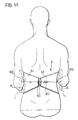
- Figures 8 to 13 show schematically the positions assumed by the two parts 51 and 52 of the element 5 when the seat S is occupied by a small person ( Figures 8 and 11), an average-sized person (Fig.ures 9 and 12), and a large person ( Figures 10 and 13) respectively.
- the butterfly-shaped lumbar support 5 assumes different profiles in different conditions in dependence on the size of the seat occupant.
- the element 5 which may even be the only support element present in the backrest, it is thus possible to afford the seat occupant adequate lumbar support and therefore an excellent degree of comfort, ensuring very good overall vertical restraint of the back against the lateral forces which arise during movements of the vehicle resulting from transverse accelerations (for example, on bends).
- the lumbar support element 5 is preferably made of a material which is intrinsically rigid in the sense that, unlike the springs used in the spring structures of seats currently produced, the parts 51, 52 are made of a rigid material such as pressed sheet metal or rigid moulded resilient material.
- the parts 51 and 52 are hinged to each other so that they can bend as a whole under the pressure of the back of the seat occupant S, whilst their facing inner ends simultaneously move apart of together as a result of the pressure exerted by the occupant leaning on the backrest.
- the element 5 can open out if the seat occupant has a wide back or, on the other hand, can close up if the occupant has a small waist.
- the element 5 as a whole must have a dual capacity for movement or profile adjustment, represented by the greater or lesser concavity of the profile defined jointly by the two parts 51, 52 (relative inclination) and by their greater or lesser separation (relative spacing) in order better to accommodate wide or narrow backs.
- To this capacity for movement may advantageously be added a capacity to perform a rocking movement about a horizontal axis so that the element 5 can adapt itself to vertebral columns with lumbar curves which are high up or low down.
- a tie rod 103 with two associated springs 104 extends between the two parts 51, 52, however, again through apertures 101.
- Each of the springs 104 acts under compression between an enlarged end 105 of the tie rod 103 and a corresponding return or flange 106 of the respective part 51, 52, in which the aperture 101 is provided.
- springs 102, 104 may, to advantage, be replaced by other functionally equivalent elements, for example, a rubber ring 107 which connects the two inner ends of the parts 51, 52 resiliently according to the solution which will be referred to more explicitly below.
- FIG. 16 A further development of the invention, to which Figures 16 to 22 relate specifically, provides for the use of a positive adjustment system for the element 5.
- this is a kinematic mechanism which can move the two parts 51 and 52 away from and towards each other so as to achieve the best adjustment for backs of different widths.
- the tie rod 103 on which the springs 104 are fitted assumes the character of an actual shaft which can be rotated about its principle axis (which extends horizontally, transverse the seat S). This is achieved by the positive operation of a knob 108 projecting from one side of the seat S.
- this manual operation may be replaced by automatic operation, for example, with the provision of an electric motor which can rotate the tie rod-shaft 103.
- two cams or similar eccentric bodies 109 may be mounted on its ends and, as a result of the rotation of the shaft 103 (see in particular the side view of Figure 17), these urge the parts 51, 52 forwards by a distance which can be adjusted selectively by means of the knob 108.
- Holes 111 through which ties 112 pass are provided in the cross member 110.
- the ties 112 act as traction cables acting between the cross member 110 (which is substantially rigid) and the parts 51, 52 so as to modify their orientation positively.
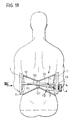
- the ties 112 can be operated selectively by a biasing system (of known type) controlled by a knob 113 ( Figures 18 and 19).
- the tension exerted on the ties 112 causes the parts 51 and 52 to open out so as gradually to widen the profile of the backrest.
- the parts 51, 52 open out so as to reduce the transverse restraint of the seat.
- the support rods or wires 100 may, to advantage, assume the profiles of L-shaped springs in order to fulfil the dual role of supporting the element 5 and biasing the parts 51, 52 together.
- Figures 23 to 26 provides for the use of an operating system which combines elements of an alternative solution with some of the aspects described above.
- this further variant aims to simplify the mechanism for moving the band-like lumbar support 5.
- the tie 115 is anchored at a first end 115a to a fixed point on one of the vertical uprights of the frame 1 (for example, the upright on the right-hand side of the seat with reference to Figures 23 to 26), extends generally around the back of the parts 51, 52, for example, through guide formations 116 (which may also be present in the other embodiments), projecting from the rear faces of the parts 51, 52, to form a loop around the opposite upright 1, and its remaining pass 117 then returns towards the tensioning element 113.
Landscapes
- Engineering & Computer Science (AREA)
- Aviation & Aerospace Engineering (AREA)
- Transportation (AREA)
- Mechanical Engineering (AREA)
- Chair Legs, Seat Parts, And Backrests (AREA)
Applications Claiming Priority (4)
| Application Number | Priority Date | Filing Date | Title |
|---|---|---|---|
| IT6781589 | 1989-09-28 | ||
| IT8967815A IT1233906B (it) | 1989-09-28 | 1989-09-28 | Schienale per sedili, particolarmente sedili automobilistici |
| IT67270A IT1240185B (it) | 1990-04-11 | 1990-04-11 | Schienale per sedili, particolarmente sedili automobilistici. |
| IT6727090 | 1990-04-11 |
Publications (2)
| Publication Number | Publication Date |
|---|---|
| EP0420824A1 true EP0420824A1 (de) | 1991-04-03 |
| EP0420824B1 EP0420824B1 (de) | 1994-01-05 |
Family
ID=26329745
Family Applications (1)
| Application Number | Title | Priority Date | Filing Date |
|---|---|---|---|
| EP90830404A Expired - Lifetime EP0420824B1 (de) | 1989-09-28 | 1990-09-18 | Eine Rückenlehne für einen Sitz, insbesondere einen Kraftfahrzeugsitz |
Country Status (5)
| Country | Link |
|---|---|
| EP (1) | EP0420824B1 (de) |
| DE (1) | DE69005766T2 (de) |
| ES (1) | ES2047905T3 (de) |
| PL (1) | PL165770B1 (de) |
| RU (1) | RU2010736C1 (de) |
Cited By (16)
| Publication number | Priority date | Publication date | Assignee | Title |
|---|---|---|---|---|
| EP0563709A3 (de) * | 1992-03-24 | 1994-03-02 | Fiat Auto Spa | |
| WO1995021559A1 (en) * | 1994-02-10 | 1995-08-17 | Fisher-Price, Inc. | Adjustable seat back |
| EP0808746A3 (de) * | 1996-05-20 | 1998-08-19 | LEAR CORPORATION ITALIA S.p.A. | Lendenstütze für die Rückenlehne eines Kraftfahrzeugsitzes |
| US6994399B2 (en) * | 2001-11-28 | 2006-02-07 | L&P Swiss Holding Company | Seat back suspension arrangement |
| WO2007030893A1 (en) * | 2005-09-16 | 2007-03-22 | Robert Andrew Crosbie | Back support for a chair |
| US7201446B2 (en) * | 2001-07-11 | 2007-04-10 | Alfmeier Corporation | Integrated adjustable lumbar support and trim attachment system |
| US7328950B2 (en) | 2005-05-18 | 2008-02-12 | Schukra Of North America, Ltd. | Dual hinge belt lumbar |
| US7425036B2 (en) | 2005-08-23 | 2008-09-16 | Schukra Of North America, Ltd. | Comfort belt spring pulley |
| US7874616B2 (en) | 2008-09-18 | 2011-01-25 | Lear Corporation | Horizontal lumbar suspension for vehicle seats |
| US8313143B2 (en) | 2005-03-01 | 2012-11-20 | Haworth, Inc. | Chair back with lumbar and pelvic supports |
| US9193287B2 (en) | 2012-09-13 | 2015-11-24 | Leggett & Platt Canada Co. | Lumbar support system |
| US9193280B2 (en) | 2012-09-13 | 2015-11-24 | Leggett & Platt Canada Co. | Lumbar support system |
| US9199565B2 (en) | 2012-09-13 | 2015-12-01 | Leggett & Platt Canada Co. | Lumbar support system |
| US10427569B2 (en) | 2015-01-26 | 2019-10-01 | Kongsberg Automotive, Inc. | Adjustment mechanism for a seat |
| US10632882B2 (en) | 2012-09-13 | 2020-04-28 | Leggett & Platt Canada Co. | Lumbar support system |
| CN116587934A (zh) * | 2023-04-11 | 2023-08-15 | 成都赛力斯科技有限公司 | 一种汽车座椅形变控制方法、装置和汽车 |
Families Citing this family (10)
| Publication number | Priority date | Publication date | Assignee | Title |
|---|---|---|---|---|
| IT1249658B (it) * | 1991-06-11 | 1995-03-09 | Fiat Auto Spa | Elemento di sopporto dorsale per sedili, particolarmente sedili automobilistici. |
| IT225507Y1 (it) * | 1991-10-18 | 1996-11-18 | Clerprem Spa | Elemento di supporto per sedili utilizzabile ad esempio quale elemento di supporto lombare per schienali di sedili automobilistici |
| IT1250850B (it) * | 1991-10-31 | 1995-04-21 | Fiat Auto Spa | Schienale per sedili, particolarmente sedili automobilistici. |
| IT1257058B (it) * | 1992-07-27 | 1996-01-05 | Fiat Auto Spa | Elemento di sopporto dorsale persedili, particolarmente sedili automobilistici. |
| GB2335844A (en) * | 1998-03-27 | 1999-10-06 | Youngflex Ag | Seat assembly providing adjustable lumbar support |
| RU2210510C1 (ru) * | 2002-01-08 | 2003-08-20 | Санкт-Петербургский государственный аграрный университет | Сиденье оператора строительной машины |
| WO2006105989A1 (de) | 2005-04-08 | 2006-10-12 | Alfmeier Präzision AG Baugruppen und Systemlösungen | Fahrzeugsitz mit lordosenstütze |
| US7780233B2 (en) | 2005-06-02 | 2010-08-24 | Schukra Of North America, Ltd. | Belt extension apparatus |
| US8439441B2 (en) | 2010-09-29 | 2013-05-14 | Lear Corporation | Adjustable lumbar assembly for vehicle seats |
| US9604560B1 (en) | 2015-11-13 | 2017-03-28 | Kongsberg Automotive, Inc. | Assembly for adjusting a lumbar region of a seat |
Citations (4)
| Publication number | Priority date | Publication date | Assignee | Title |
|---|---|---|---|---|
| EP0109572A1 (de) * | 1982-10-25 | 1984-05-30 | International Positioning Systems, Ltd. | Vorrichtung zum Stützen und Positionieren des menschlichen Körpers und Verfahren zum deren Einstellen |
| EP0312506A1 (de) * | 1987-10-16 | 1989-04-19 | FIAT AUTO S.p.A. | Einstellbare Rückensitzlehne für Kraftfahrzeuge |
| EP0322535A1 (de) * | 1987-12-28 | 1989-07-05 | Wickes Manufacturing Company | Verstellbare Lendenstütze |
| EP0328137A2 (de) * | 1988-02-12 | 1989-08-16 | Piero Marchino | Feder- und Umklammerungselement für einen Sitz und/oder eine Rückenlehne und Sitz, der mit diesem Element ausgerüstet ist |
-
1990
- 1990-09-18 DE DE90830404T patent/DE69005766T2/de not_active Expired - Fee Related
- 1990-09-18 ES ES90830404T patent/ES2047905T3/es not_active Expired - Lifetime
- 1990-09-18 EP EP90830404A patent/EP0420824B1/de not_active Expired - Lifetime
- 1990-09-27 RU SU904831045A patent/RU2010736C1/ru active
- 1990-09-28 PL PL90287108A patent/PL165770B1/pl not_active IP Right Cessation
Patent Citations (4)
| Publication number | Priority date | Publication date | Assignee | Title |
|---|---|---|---|---|
| EP0109572A1 (de) * | 1982-10-25 | 1984-05-30 | International Positioning Systems, Ltd. | Vorrichtung zum Stützen und Positionieren des menschlichen Körpers und Verfahren zum deren Einstellen |
| EP0312506A1 (de) * | 1987-10-16 | 1989-04-19 | FIAT AUTO S.p.A. | Einstellbare Rückensitzlehne für Kraftfahrzeuge |
| EP0322535A1 (de) * | 1987-12-28 | 1989-07-05 | Wickes Manufacturing Company | Verstellbare Lendenstütze |
| EP0328137A2 (de) * | 1988-02-12 | 1989-08-16 | Piero Marchino | Feder- und Umklammerungselement für einen Sitz und/oder eine Rückenlehne und Sitz, der mit diesem Element ausgerüstet ist |
Cited By (19)
| Publication number | Priority date | Publication date | Assignee | Title |
|---|---|---|---|---|
| EP0563709A3 (de) * | 1992-03-24 | 1994-03-02 | Fiat Auto Spa | |
| WO1995021559A1 (en) * | 1994-02-10 | 1995-08-17 | Fisher-Price, Inc. | Adjustable seat back |
| EP0808746A3 (de) * | 1996-05-20 | 1998-08-19 | LEAR CORPORATION ITALIA S.p.A. | Lendenstütze für die Rückenlehne eines Kraftfahrzeugsitzes |
| US7201446B2 (en) * | 2001-07-11 | 2007-04-10 | Alfmeier Corporation | Integrated adjustable lumbar support and trim attachment system |
| US6994399B2 (en) * | 2001-11-28 | 2006-02-07 | L&P Swiss Holding Company | Seat back suspension arrangement |
| US9538849B2 (en) | 2005-03-01 | 2017-01-10 | Haworth, Inc. | Chair back with lumbar and pelvic supports |
| US8313143B2 (en) | 2005-03-01 | 2012-11-20 | Haworth, Inc. | Chair back with lumbar and pelvic supports |
| US8845024B2 (en) | 2005-03-01 | 2014-09-30 | Haworth, Inc. | Chair back with lumbar and pelvic supports |
| US7328950B2 (en) | 2005-05-18 | 2008-02-12 | Schukra Of North America, Ltd. | Dual hinge belt lumbar |
| US7425036B2 (en) | 2005-08-23 | 2008-09-16 | Schukra Of North America, Ltd. | Comfort belt spring pulley |
| WO2007030893A1 (en) * | 2005-09-16 | 2007-03-22 | Robert Andrew Crosbie | Back support for a chair |
| US7874616B2 (en) | 2008-09-18 | 2011-01-25 | Lear Corporation | Horizontal lumbar suspension for vehicle seats |
| US9193280B2 (en) | 2012-09-13 | 2015-11-24 | Leggett & Platt Canada Co. | Lumbar support system |
| US9199565B2 (en) | 2012-09-13 | 2015-12-01 | Leggett & Platt Canada Co. | Lumbar support system |
| US9193287B2 (en) | 2012-09-13 | 2015-11-24 | Leggett & Platt Canada Co. | Lumbar support system |
| US9764670B2 (en) | 2012-09-13 | 2017-09-19 | Leggett & Platt Canada Co. | Lumbar support system |
| US10632882B2 (en) | 2012-09-13 | 2020-04-28 | Leggett & Platt Canada Co. | Lumbar support system |
| US10427569B2 (en) | 2015-01-26 | 2019-10-01 | Kongsberg Automotive, Inc. | Adjustment mechanism for a seat |
| CN116587934A (zh) * | 2023-04-11 | 2023-08-15 | 成都赛力斯科技有限公司 | 一种汽车座椅形变控制方法、装置和汽车 |
Also Published As
| Publication number | Publication date |
|---|---|
| ES2047905T3 (es) | 1994-03-01 |
| PL165770B1 (en) | 1995-02-28 |
| EP0420824B1 (de) | 1994-01-05 |
| PL287108A1 (en) | 1991-05-06 |
| DE69005766D1 (de) | 1994-02-17 |
| DE69005766T2 (de) | 1994-04-28 |
| RU2010736C1 (ru) | 1994-04-15 |
Similar Documents
| Publication | Publication Date | Title |
|---|---|---|
| EP0420824B1 (de) | Eine Rückenlehne für einen Sitz, insbesondere einen Kraftfahrzeugsitz | |
| US5026116A (en) | Adjustable backrest for the seats of vehicles, particularly cars | |
| EP0714808B1 (de) | Sitz mit verstellbarer Lendenstütze | |
| EP0328137B1 (de) | Feder- und Umklammerungselement für einen Sitz und/oder eine Rückenlehne und Sitz, der mit diesem Element ausgerüstet ist | |
| EP0926969B1 (de) | Rückenlehne für einen sitz | |
| EP1608533B1 (de) | Sitz mit einstellbarem stützsystem | |
| EP2359717B1 (de) | Rückenlehne für einen stuhl | |
| JPH08502187A (ja) | 可調節型の腰支持具 | |
| US3627379A (en) | Backrest for a seat especially of a motor vehicle | |
| JP2000517269A (ja) | ヘッドレストを備えた車両の座席 | |
| EP1966002A1 (de) | Autositz | |
| EP0113645B1 (de) | Kopfstütze für Kraftfahrzeugsitze | |
| WO2011029199A1 (en) | Pelvic and lumbar support system | |
| EP0563709B1 (de) | Sitz mit Lendenstütze, insbesondere für Kraftfahrzeuge | |
| US5468048A (en) | Seat back with adjustable support | |
| JPH0775608A (ja) | 車両用シート | |
| EP0808746A2 (de) | Lendenstütze für die Rückenlehne eines Kraftfahrzeugsitzes | |
| JP2000175761A (ja) | 車両用シートクッション | |
| JP2917287B2 (ja) | シートバック | |
| JPH0682949U (ja) | 車両用座席構造 | |
| KR200159427Y1 (ko) | 수평조절식 헤드 레스트 | |
| JP7635662B2 (ja) | シート装置 | |
| JPH11253268A (ja) | 車両用シート | |
| JP7052693B2 (ja) | 車両シート構造 | |
| JP7200050B2 (ja) | シートバック |
Legal Events
| Date | Code | Title | Description |
|---|---|---|---|
| PUAI | Public reference made under article 153(3) epc to a published international application that has entered the european phase |
Free format text: ORIGINAL CODE: 0009012 |
|
| AK | Designated contracting states |
Kind code of ref document: A1 Designated state(s): DE ES FR GB SE |
|
| 17P | Request for examination filed |
Effective date: 19910222 |
|
| 17Q | First examination report despatched |
Effective date: 19920917 |
|
| GRAA | (expected) grant |
Free format text: ORIGINAL CODE: 0009210 |
|
| AK | Designated contracting states |
Kind code of ref document: B1 Designated state(s): DE ES FR GB SE |
|
| REF | Corresponds to: |
Ref document number: 69005766 Country of ref document: DE Date of ref document: 19940217 |
|
| REG | Reference to a national code |
Ref country code: ES Ref legal event code: FG2A Ref document number: 2047905 Country of ref document: ES Kind code of ref document: T3 |
|
| ET | Fr: translation filed | ||
| PLBE | No opposition filed within time limit |
Free format text: ORIGINAL CODE: 0009261 |
|
| STAA | Information on the status of an ep patent application or granted ep patent |
Free format text: STATUS: NO OPPOSITION FILED WITHIN TIME LIMIT |
|
| 26N | No opposition filed | ||
| EAL | Se: european patent in force in sweden |
Ref document number: 90830404.1 |
|
| REG | Reference to a national code |
Ref country code: GB Ref legal event code: IF02 |
|
| PGFP | Annual fee paid to national office [announced via postgrant information from national office to epo] |
Ref country code: DE Payment date: 20030821 Year of fee payment: 14 |
|
| PG25 | Lapsed in a contracting state [announced via postgrant information from national office to epo] |
Ref country code: DE Free format text: LAPSE BECAUSE OF NON-PAYMENT OF DUE FEES Effective date: 20050401 |
|
| PGFP | Annual fee paid to national office [announced via postgrant information from national office to epo] |
Ref country code: ES Payment date: 20060802 Year of fee payment: 17 |
|
| PGFP | Annual fee paid to national office [announced via postgrant information from national office to epo] |
Ref country code: GB Payment date: 20060811 Year of fee payment: 17 |
|
| PGFP | Annual fee paid to national office [announced via postgrant information from national office to epo] |
Ref country code: SE Payment date: 20060831 Year of fee payment: 17 |
|
| PG25 | Lapsed in a contracting state [announced via postgrant information from national office to epo] |
Ref country code: SE Free format text: LAPSE BECAUSE OF NON-PAYMENT OF DUE FEES Effective date: 20070919 |
|
| EUG | Se: european patent has lapsed | ||
| GBPC | Gb: european patent ceased through non-payment of renewal fee |
Effective date: 20070918 |
|
| REG | Reference to a national code |
Ref country code: FR Ref legal event code: ST Effective date: 20080531 |
|
| PG25 | Lapsed in a contracting state [announced via postgrant information from national office to epo] |
Ref country code: FR Free format text: LAPSE BECAUSE OF NON-PAYMENT OF DUE FEES Effective date: 20071001 |
|
| PGFP | Annual fee paid to national office [announced via postgrant information from national office to epo] |
Ref country code: FR Payment date: 20060929 Year of fee payment: 17 |
|
| PG25 | Lapsed in a contracting state [announced via postgrant information from national office to epo] |
Ref country code: GB Free format text: LAPSE BECAUSE OF NON-PAYMENT OF DUE FEES Effective date: 20070918 |
|
| REG | Reference to a national code |
Ref country code: ES Ref legal event code: FD2A Effective date: 20070919 |
|
| PG25 | Lapsed in a contracting state [announced via postgrant information from national office to epo] |
Ref country code: ES Free format text: LAPSE BECAUSE OF NON-PAYMENT OF DUE FEES Effective date: 20070919 |