EP0421145B1 - Machine d'impression lithographique - Google Patents
Machine d'impression lithographique Download PDFInfo
- Publication number
- EP0421145B1 EP0421145B1 EP19900117234 EP90117234A EP0421145B1 EP 0421145 B1 EP0421145 B1 EP 0421145B1 EP 19900117234 EP19900117234 EP 19900117234 EP 90117234 A EP90117234 A EP 90117234A EP 0421145 B1 EP0421145 B1 EP 0421145B1
- Authority
- EP
- European Patent Office
- Prior art keywords
- rubber cover
- cylinder
- blanket
- rubber
- layer
- Prior art date
- Legal status (The legal status is an assumption and is not a legal conclusion. Google has not performed a legal analysis and makes no representation as to the accuracy of the status listed.)
- Expired - Lifetime
Links
- 238000007639 printing Methods 0.000 title claims description 101
- 229920001971 elastomer Polymers 0.000 claims description 169
- 239000005060 rubber Substances 0.000 claims description 169
- 239000000463 material Substances 0.000 claims description 76
- 238000005096 rolling process Methods 0.000 claims description 11
- 238000010276 construction Methods 0.000 claims description 6
- 239000006260 foam Substances 0.000 claims description 6
- 239000012530 fluid Substances 0.000 claims description 3
- 239000002861 polymer material Substances 0.000 claims description 3
- 239000007787 solid Substances 0.000 claims description 3
- 238000011144 upstream manufacturing Methods 0.000 claims 1
- 239000002759 woven fabric Substances 0.000 claims 1
- 230000002093 peripheral effect Effects 0.000 description 15
- 239000002184 metal Substances 0.000 description 10
- 229910052751 metal Inorganic materials 0.000 description 10
- 238000012546 transfer Methods 0.000 description 10
- 230000001427 coherent effect Effects 0.000 description 8
- 238000007645 offset printing Methods 0.000 description 8
- 230000000694 effects Effects 0.000 description 7
- 230000007423 decrease Effects 0.000 description 4
- 230000006835 compression Effects 0.000 description 3
- 238000007906 compression Methods 0.000 description 3
- 244000043261 Hevea brasiliensis Species 0.000 description 2
- PXHVJJICTQNCMI-UHFFFAOYSA-N Nickel Chemical compound [Ni] PXHVJJICTQNCMI-UHFFFAOYSA-N 0.000 description 2
- 230000002411 adverse Effects 0.000 description 2
- 239000004744 fabric Substances 0.000 description 2
- 229920003052 natural elastomer Polymers 0.000 description 2
- 229920001194 natural rubber Polymers 0.000 description 2
- 230000010355 oscillation Effects 0.000 description 2
- 229920000642 polymer Polymers 0.000 description 2
- 229920003051 synthetic elastomer Polymers 0.000 description 2
- 239000000853 adhesive Substances 0.000 description 1
- 230000001070 adhesive effect Effects 0.000 description 1
- 238000013459 approach Methods 0.000 description 1
- 238000004891 communication Methods 0.000 description 1
- 238000013461 design Methods 0.000 description 1
- 238000000034 method Methods 0.000 description 1
- 229910052759 nickel Inorganic materials 0.000 description 1
- 239000011343 solid material Substances 0.000 description 1
- 238000005507 spraying Methods 0.000 description 1
- 239000005061 synthetic rubber Substances 0.000 description 1
- 239000002699 waste material Substances 0.000 description 1
Images


Classifications
-
- B—PERFORMING OPERATIONS; TRANSPORTING
- B41—PRINTING; LINING MACHINES; TYPEWRITERS; STAMPS
- B41N—PRINTING PLATES OR FOILS; MATERIALS FOR SURFACES USED IN PRINTING MACHINES FOR PRINTING, INKING, DAMPING, OR THE LIKE; PREPARING SUCH SURFACES FOR USE AND CONSERVING THEM
- B41N6/00—Mounting boards; Sleeves Make-ready devices, e.g. underlays, overlays; Attaching by chemical means, e.g. vulcanising
-
- B—PERFORMING OPERATIONS; TRANSPORTING
- B41—PRINTING; LINING MACHINES; TYPEWRITERS; STAMPS
- B41F—PRINTING MACHINES OR PRESSES
- B41F27/00—Devices for attaching printing elements or formes to supports
-
- B—PERFORMING OPERATIONS; TRANSPORTING
- B41—PRINTING; LINING MACHINES; TYPEWRITERS; STAMPS
- B41F—PRINTING MACHINES OR PRESSES
- B41F30/00—Devices for attaching coverings or make-ready devices; Guiding devices for coverings
- B41F30/04—Devices for attaching coverings or make-ready devices; Guiding devices for coverings attaching to transfer cylinders
-
- B—PERFORMING OPERATIONS; TRANSPORTING
- B41—PRINTING; LINING MACHINES; TYPEWRITERS; STAMPS
- B41N—PRINTING PLATES OR FOILS; MATERIALS FOR SURFACES USED IN PRINTING MACHINES FOR PRINTING, INKING, DAMPING, OR THE LIKE; PREPARING SUCH SURFACES FOR USE AND CONSERVING THEM
- B41N10/00—Blankets or like coverings; Coverings for wipers for intaglio printing
Definitions
- the present invention relates to an offset printing machine.
- the smearing of the printed image is also caused by the fact that it slides back and forth between the surfaces at the printing nip where the printed image is transferred to the rubber blanket.
- the surfaces thus slide against one another, which leads to smearing of the printed image if the speed of the blanket surface is either greater or less than the speed of the surface which transfers the printed image to the blanket.
- the object of the present invention is to improve the print quality achieved by an offset printing press by eliminating or at least minimizing the smear effect in printed images.
- the offset printing machine comprises a blanket cylinder on which there is a blanket which applies the printed image to the sheet material.
- a color transfer surface on the plate cylinder transfers the print image to the sheet material.
- the ink-transferring surface on the plate cylinder and the blanket are in rolling contact with one another at the printing gap which is formed by the plate and the blanket cylinder.
- the blanket is in the form of a tube that has contiguous, gap-free exterior and interior surfaces.
- the blanket is removably mounted on the outer peripheral surface of the blanket cylinder.
- the outer surface of the rubber blanket is in rolling contact with the ink-transferring surface on the plate cylinder at the resulting pressure gap. Since the outer circumferential surface of the blanket is coherent and gap-free, a bumpless and vibration-free rolling contact is achieved between the blanket and the ink-transferring surface of the plate cylinder, thereby causing the transfer of a printed image to the blanket without smearing the printed image.
- the rubber blanket is at least partially made of a compressible material which is pressed together by the plate cylinder at the printing nip formed by the printing cylinder and rubber blanket cylinder.
- the outer surface of the rubber blanket has a circumferential speed which essentially corresponds to that at locations immediately in front of, at and behind the pressure nip. This prevents a slipping effect between the surfaces of the printing plate and the rubber blanket in front of, at and behind the printing nip, thereby avoiding smearing of the printed image.
- the solid inner layer of material absorbs the tensile stress of the blanket cylinder, thereby establishing a firm pressure relationship between the blanket and the blanket cylinder.
- This pressure relationship fixes the blanket on the blanket cylinder so that there is no relative movement while the machine is running.
- the printing press comprises means for executing a radial expansion the tubular blanket on the blanket cylinder to relieve the pressure relationship between the blanket and the blanket cylinder. When the pressure relationship is released, the blanket is manually removed from the blanket cylinder in the axial direction. In addition, the blanket must be stretched radially outward to axially apply the blanket to the blanket cylinder.
- the press has appropriate means to perform this function.
- a portion of the frame that is adjacent to an axial end of the blanket cylinder can be cleared out of the way .
- the tubular rubber blanket can be passed axially through the opening in the frame created by clearing the frame member out of the way.
- the interior of the cylinder In order to stretch the rubber blanket so that it can be applied to the cylinder, the interior of the cylinder must be supplied with compressed air. There are passages between the outer peripheral surface and the inside of the blanket cylinder. Compressed air conducted into the inside of the blanket cylinder is thus in communication with the inside of the blanket, so that the blanket is stretched on the blanket cylinder during application. After the blanket is placed on the outer circumference of the blanket cylinder, the compressed air can be removed. The blanket then contracts around the blanket cylinder and fits tightly and encompasses the circumference of the cylinder over the axial width of the blanket and in the circumferential direction of the inner surface of the blanket. This pressure relationship between the rubber blanket and the rubber blanket cylinder can be eliminated by supplying the interior of the rubber blanket cylinder with compressed air again, so that the rubber blanket can be removed manually from the cylinder.
- the lithographic printing machine 10 prints on opposite sides of a sheet of sheet material 12.
- the lithographic printing machine 10 comprises identical lower and upper blanket cylinders 14, 16.
- the blankets 18, 20 are mounted on the blanket cylinders 14, 16 and transfer the printed images to the opposite sides of the Web 12.
- the upper and lower plate cylinders 22, 24 carry printing plates which are in rolling contact with the rubber blankets 18, 20 at the printing nips 26, 28.
- the printed images are applied to the blankets 18, 20 by means of the printing plates on the plate cylinders 22, 24. These printed images are in turn applied to opposite sides of the web 12 using the rubber blankets 18, 20.
- the diameter of the blanket 18 and the diameter of the blanket cylinder 14 can be minimized.
- a printed image can thus be applied to the surface 40 of the rubber blanket over the entire area of the surface 40.
- the printed image can extend over an area in which a gap has previously been formed in the surface of known blanket cylinders.
- the rubber blanket 18 is provided with a cylindrical outer surface 40 which is coherent and free of gaps, which reduces waste which arises during the printing process. In a specific embodiment of the invention, approximately 6.35 mm (0.25 inches) are saved with each revolution of the blanket cylinder 14.
- the rubber blanket 18 consists at least partially of a compressible material. When a force is applied to the compressible material of the rubber blanket 18, the volume of the compressible material decreases. The material of the rubber blanket 18 is compressed by the rigid plate cylinder 22 at the pressure nip 26. Since the rubber blanket consists at least partially of compressible material, the rubber blanket 18 yields radially inward without deforming the rubber blanket radially outward at the pressure gap 26.
- the peripheral speed of the rubber blanket is the same at all points immediately in front of the printing gap 26, at the printing gap and immediately behind the printing gap formed by the blanket cylinder 18 and plate cylinder 22. Since the speed of dots on the surface 40 of the blanket on the opposite sides of the printing nip 26 and in the middle of the printing nip is the same, the surface 40 of the blanket cylinder and the surface 42 of the printing plate on the plate cylinder 22 do not slide against each other at the printing nip. This prevents smearing of the printed image when the printing plate is applied to the plate cylinder 22 on the rubber blanket 18.
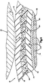
- the blanket 18 is made of a non-compressible material, e.g. a blanket 18a in FIG. 2 would give way to the non-compressible material of the blanket radially outward and laterally due to a pressure exerted on the blanket by a pressure plate on the plate cylinder 22a in the circumferential direction, as schematically illustrated in FIG. 2.
- the non-compressible material of the rubber blanket 18a which is displaced by the fact that the rubber blanket yields at the pressure gap 26, forms arches 46a and 48a on opposite sides of the pressure gap 26a.
- the curvatures 46a and 48a are formed because the volume of the non-compressible material from which the rubber blanket 18a is made remains unchanged, even though the non-compressible material yields at the pressure gap 26a. Therefore, the volume of the material that is displaced from the pressure plate of the plate cylinder 22 corresponds to the volume of the material of the bulges 46a and 48a.
- the volume of the material displaced from the printing plate on the plate cylinder 22a corresponds to the volume of the overlapping portions of the contours of the cylindrical outer surface 40a of the rubber blanket 18a and the cylindrical outer surface 42a of the printing plate on the plate cylinder 22a. This volume of material is located between the curved plane - as indicated by the dashed line 50a in FIG. 2 - and the curved outer surface 42a of the printing plate on the plate cylinder 22a and extends over the axial extent of the plate and blanket cylinders.
- the speed of a dot on the surface of the non-compressible material of the blanket 18a (Fig. 2) varies as the dot moves from one side of the nip 26a to the opposite side of the nip.
- the material is accelerated to the extent and the peripheral speed increases as the material in the arch 46a moves into the pressure gap 36a.
- the pressure gap 26a is left and the curvature 48a is moved in, the non-compressible material loses speed and the peripheral speed decreases.
- a point 52a on the surface of the dome 46a moves slower than a point 54a in the center of the pressure gap 26a.
- the situation is similar with a point 56a on the surface of the curvature 48a which moves more slowly than the point 54a in the middle of the gap 26a.
- the magnitude of the difference in the peripheral speed of the non-compressible material of the blanket 18a at the bulges 46a and 48a and the center of the pressure gap 26a depends on the degree of yield of the non-compressible material of the rubber blanket cylinder at the pressure gap.
- the peripheral speed of the non-compressible blanket cylinder material moving through the nip 26a (Fig. 2) first increases and then decreases, the smear effect occurs on printed images caused by the sliding of the outer surface 40a of the rubber blanket 18a against the outer surface 42a of the printing plate on the Plate cylinder 22a is caused.
- the surface 40a of the blanket 18a and the surface 42a of the printing plate on the plate cylinder 22a have the same speed at locations distant from the printing nip 26a. If - during the rotational movement of the rubber blanket 18a in the opposite direction (as shown in FIG. 2) - a point on the surface 40a approaches the arch 46a, the speed of the point on the surface of the rubber blanket 18 reduces to a peripheral speed, which is less than the peripheral speed of the printing plate on the plate cylinder 22a.
- the speed of the point increases to a speed which is greater than the peripheral speed of the printing plate the plate cylinder 22a.
- the speed of movement of the point decreases as this point moves away from the center of the pressure gap 26a and towards a point on the bulge 48a.
- the speed of a point on the surface of the bulge 48a is less than the peripheral speed of the printing plate on the plate cylinder 22a.
- the rubber blanket 18 in FIG. 1 is configured differently than the rubber blanket 18a in FIG. 2.
- the rubber blanket 18a in FIG. 2 consists of a non-compressible material.
- the rubber blanket 18 of FIG. 1 consists at least partially of a compressible material. For this reason, the rubber blanket 18 of FIG. 1 does not deform in the manner shown schematically in FIG. 2.
- the rubber blanket 18 has a hollow tubular construction.
- the tubular rubber blanket 18 is firmly connected to the rubber blanket cylinder 14 and rotates with the rubber blanket cylinder under the influence of the drive unit 38.
- the tubular rubber blanket 18 can, however, be removed from the rubber blanket cylinder 14 and replaced, as will be explained further below.
- the tubular rubber blanket 18 can have various design options, in this exemplary embodiment according to the invention it is constructed in multiple layers.
- the blanket 18 includes a cylindrical outer layer 66 (Fig. 3) on which the soft coherent outer surface 40 of the blanket is attached.
- the cylindrical outer layer 66 consists of an elastically yielding and non-compressible polymer material, such as. B. made of natural rubber or synthetic rubber.
- a second cylindrical layer / intermediate cylindrical layer 68 (FIG. 3) is arranged radially within the outer layer 66.
- the intermediate layer 68 has a cylindrical outer surface 70 which is attached to a cylindrical inner surface 72 of the outer layer 66.
- the intermediate cylindrical layer 68 is made of an elastically compressible polymeric material, such as e.g. made from natural rubber or from artificial rubber.
- a third cylindrical layer 74 is arranged radially within the second layer 68.
- the third layer 74 has a cylindrical outer surface 76 which bears against a cylindrical inner surface 78 of the second layer and is fixedly connected thereto.
- the third layer 74 may be made of a different material, in the illustrated embodiment of the invention the third layer is made of the same non-compressible material as the outer layer 66.
- the third layer 74 is fixedly connected to a hollow rigid metal inner layer which comprises a bearing bush 80 which is fixedly connected to the blanket cylinder 14.
- a cylindrical inner surface 82 of the third layer 74 is fixedly connected to a cylindrical outer surface 84 of the bush 80.
- a cylindrical inner surface 86 of the bush 80 bears against a cylindrical outer surface 88 of the cylinder 14.
- the sleeve 80 is made of nickel and is releasably connected to the blanket cylinder 14 so that the entire blanket 18 can be pushed axially onto the rigid metal blanket cylinder 14 (FIG. 1) and / or removed from the metal blanket cylinder. Due to this construction, the rubber blanket 18 can be replaced after a certain period of use.
- the bushing 80 is applied under tension to the blanket cylinder 14 in order to establish a firm pressure relationship between the blanket 18 and the blanket cylinder 14. Due to this pressure relationship, the blanket 18 is attached to the blanket cylinder 14, so that no re during printing press operation relative movement between the blanket and blanket cylinder results.
- the printing machine includes means for radial expansion of the tubular blanket on the blanket cylinder to relieve the pressure relationship between blanket 18 and blanket cylinder 14, as will be described below. When the pressure relationship is released, the blanket 18 can be manually removed from the blanket cylinder 14 in the axial direction. Likewise, the bushing 80 must be stretched radially or stretched radially outward in order to move the rubber blanket 18 onto the rubber blanket cylinder 14.
- the printing press has means for performing this function, as will be described further below.
- the cylindrical outer layer 66 consists of a non-compressible material.
- the volume enclosed by the surface 40 of the outer layer is reduced by the volume located in the space between the cylindrical outer surface 88 and surface 40 of the deformed outer layer 66. Since the outer layer 66 is made of a non-compressible material, the volume of the outer layer itself does not change when the outer layer is elastically deformed by the plate cylinder 22 as shown in FIG. 4.
- the outer layer 66 deforms without bulging radially outward on opposite sides of the pressure gap 26, similarly to the case with the rubber blanket 18a shown in FIG. 2.
- no bulges corresponding to the bulges 46a and 48a form in the outer layer 66 when the outer layer 66 of the rubber blanket 18 is deformed by the pressure plate on the plate cylinder 22 (FIG. 4).
- the velocity is substantially at locations on the surface 40 of the outer layer that are immediately in front of the pressure gap 26, in the middle of the pressure gap and immediately behind the pressure gap is equal to the speed of the surface of the printing plate on the plate cylinder 22.
- This leads to a soft rolling contact between the blanket 18 and the printing plate on the plate cylinder 22 at the printing nip 26, without this leading to the slipping effect between the surfaces 40 and 42.
- This promotes the transfer of a print image from the printing plate on the plate cylinder 22 to the blanket 18 without the print image being smeared.
- the compressible second or intermediate layer 68 consists of a compliant, bubble-containing foam.
- the bubbles lose size or disappear entirely.
- the volume of the compressible material that forms the second layer 68 is reduced.
- the tubular rubber blanket 18 and the rubber blanket cylinder 14 take up a relatively large first volume, which is enclosed by the continuous cylindrical outer surface 40 of the outer layer 66 becomes.
- the intermediate layer 68 contains relatively large bubbles and occupies a relatively large first volume / initial volume.
- the rubber blanket 18 is placed on the printing plate on the plate cylinder 22 (FIG. 4)
- the outer layer 66 of the rubber blanket 18 is deformed radially inwards. Due to the deformation of the tubular outer layer 66, the rubber blanket 18 takes up a volume which is smaller than the original or undeformed volume.
- the total volume of the outer layer 66 remains constant, and the outer layer does not bulge outward next to opposite sides of the pressure gap 26 as in the case of the rubber blanket 14a illustrated in FIG. 2.
- the intermediate layer 68 of the rubber blanket 18 is compressed to a volume that is smaller than the initial volume of the layer 68.
- the difference between the initial volume of the second layer 68 (FIG. 3) and the compressed volume of the second layer (FIG. 4) corresponds to the volume between the cylindrical outer surface 88 in FIG. 4 and the outer surface 40 of the outer layer 66. Therefore, it takes place reducing the volume of space occupied by the blanket 18 by compressing the second layer 68, and only the outer layer 66 is deformed radially inward.
- the rubber blanket 18 can be designed differently than illustrated in the embodiment of FIGS. 3 and 4.
- a deformable fabric or non-stretch material may be provided between layers 66, 68 and 74 or in each of these layers. The number of layers could be increased as well as reduced.
- the compressible second layer 68 is preferably formed from a polymer foam having uniform stiffness, the second layer could be formed from cylindrical inner and outer portions of bubble-containing foam of different stiffness.
- the compressible intermediate layer 68 could also be made of a material other than foam, e.g. from a resiliently deformable network or fabric.
- the rubber blanket 18 is formed by spraying adhesive onto the cylindrical outer surface 84 of the metal bushing 80. Preformed strips of material are then wrapped in layers around the bushing. The strips comprise strips of the non-compressible material of the outer layer 66, the compressible material of the second layer 68 and the non-compressible material of the third layer 74. The rubber material of the strips is then vulcanized onto it so that a solid body is formed which contacts the metal bushing 80 surrounds.
- the blanket 18 could be formed as a flat planar material part, which is then wrapped around the sleeve 80 and adheres to it. In this case, the opposite ends of the material part would abut.
- the blanket 20 has the same construction.
- the blanket 20 cooperates with the printing plate on the plate cylinder 24 at the printing nip 28 in the same way as the rubber blanket 18 with the printing plate on the plate cylinder 22 at the printing nip 26.
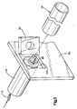
- the portion 94 of the frame is brought from the closed state to the open state illustrated in FIG. 5. This creates an opening 102 in the frame 96 through which the rubber blanket 18 can be passed.
- the movable section 94 of the frame is pivotably mounted about a vertical axis by means of a joint (not shown) which connects the movable section 94 and the frame 96 to one another.
- the movable section 94 could - if desired - also be stored in another way.
- the end of the blanket cylinder 14 opposite the side frame 96 supports the entire weight of the blanket cylinder.
- a relatively strong bearing arrangement can be provided in the opposite side frame, or a counterweight can be connected to the end of the blanket cylinder 14 opposite the side frame 96.
- a rubber blanket 18 can be manually removed from the rubber blanket cylinder 14 through the opening 102 in the axial direction. A new blanket 18 is then axially aligned with the blanket cylinder 14 and pushed onto the blanket cylinder. Once the new blanket 18 has been slid onto the blanket cylinder 14, the movable section 94 of the side frame is returned to the closed condition and brought into contact with the bearing 98 to support the blanket cylinder for rotation about its horizontal central axis.
- the blanket cylinder could pivot at one end about a hinge such that it could be pivoted to a position in which the blanket could be removed from the blanket cylinder.
- the blanket 18 and the blanket cylinder 14 are connected to one another via a tight fit between the cylindrical metal bushing 80 (FIG. 3) on the inside of the blanket 18 and the outer circumference of the metal blanket cylinder 14.
- the inner surface 86 (FIG. 3) of the cylindrical sleeve 80 has a uniform diameter that is slightly smaller than the uniform diameter of the cylindrical outer surface 88 on the outside of the metal blanket cylinder 14.
- the required fit between the bushing 80 and the blanket cylinder 14 must be sufficient for the blanket 18 to lie firmly around the outer circumference of the blanket cylinder while the machine is running so that the blanket does not slip relative to the blanket cylinder.
- the blanket cylinder 14 is thus provided with radially extending passages 106 (FIG. 3).
- the radially extending passages 106 are equally spaced apart on a plurality of radial planes which extend in the blanket cylinder 14 over its entire length.
- the blanket cylinder 14 is hollow and connected to a fluid source under pressure via a line 110 (FIG. 5).
- the compressed air conducted through line 110 into the inside of the blanket cylinder 14 flows through the passages 106 to the outside (FIG. 3) and presses against the inner surface 86 of the metal bushing 80. Because of the compressed air, the metal bushing 80 elastically expands in the circumferential direction by an amount, which is sufficient to push the blanket 18 manually onto the blanket cylinder 14 with a minimum of effort.
- the interior of the blanket cylinder 14 is vented to the atmosphere.
- the bushing 80 and the blanket 18 then contract to firmly grip the cylindrical outer surface 88 of the blanket cylinder 14.
- the sleeve 80 is then held under tension by the blanket cylinder 14.
- compressed air of approximately 413.7 KPa (60 psi) is required to cause the bushing to expand.
- the amount of compressed air required for the elastic expansion of the sleeve 80 can of course vary depending on the radial thickness of the sleeve 80, the material from which the sleeve is made and the fit between the sleeve and the blanket cylinder 14.
- the aim of the present invention is to improve the print quality achieved with an offset printing press by eliminating or at least reducing the smear effect in printed images applied to sheet material 12 by the printing press.
- the printing press comprises a blanket cylinder 14 which carries a blanket 18 which transfers the printed image to the sheet material.
- An ink-transferring surface on the plate cylinder 22 transfers the print image to the rubber blanket 18.
- the ink-transferring surface and the rubber blanket are in rolling contact with one another at the pressure gap formed between the two cylinders.
- the rubber blanket 18 has an outer peripheral surface 40 which has no axially extending gap.
- the outer surface 40 of the tube is in rolling contact at the pressure gap 26 with an ink-transferring surface on the plate cylinder 22 at the pressure gap 26. Since the outer peripheral surface 40 of the rubber blanket 18 is coherent and free of gaps, a soft and vibration-free rolling contact is achieved between the ink-transferring surface of the plate cylinder and the rubber blanket, thereby enabling the transfer of a print image to the rubber blanket without smearing the print image.
- the rubber blanket 18 is at least partially made of a compressible material which is pressed together at the pressure gap 26 by the pressure plate.
- the outer surface 40 of the rubber blanket 18 has a peripheral speed which is essentially that at positions immediately in front of the pressure nip 26, at the pressure nip and immediately behind that Pressure gap corresponds. This prevents slippage between the ink-transferring surface of the plate cylinder and the rubber blanket in front of, on and behind the printing nip in order to avoid smearing of the printed image.
- the rubber blanket 18 is a tube with a cylindrical outer layer 66 made of non-compressible material and a cylindrical intermediate layer 68 made of compressible material.
- the outer layer 66 of the rubber blanket 18 can be deformed to compress the intermediate layer 68 of the rubber blanket.
- the intermediate layer 68 of the rubber blanket contains a plurality of bubbles which are relatively large before the compression of the intermediate layer of the rubber blanket and which are relatively small in a part of the intermediate layer of the rubber blanket which is compressed by deforming the outer layer of the rubber blanket.
- the rubber blanket 18 is manually pushed onto the rubber blanket cylinder 14 from one axial end.
- a section of the frame lying next to an axial end of the blanket cylinder can preferably be cleared out of the way.
- the tubular rubber blanket 18 is pushed axially through the frame 96 onto the rubber blanket cylinder 14, which is aligned with the rubber blanket.
- the interior of the cylinder must be supplied with compressed air. Passages 106 to the cylindrical outer surface 88 of the blanket cylinder 14 communicate with the interior of the blanket cylinder.
- the compressed air inside of the blanket cylinder 14 communicates with the inside of the blanket 18 to stretch the blanket when applied to the blanket cylinder.
- the compressed air can be removed.
- the rubber blanket 18 contracts around the rubber blanket cylinder 14, lies firmly against it and encloses the rubber blanket cylinder circumference over the axial width of the rubber blanket and in the circumferential direction over the inner surface 86 of the rubber blanket 18.
- compressible In the associated US priority application, the term “compressible” was used, which was translated here as “compressible”, compressible being understood to mean in particular compressible.
Landscapes
- Printing Plates And Materials Therefor (AREA)
- Supply, Installation And Extraction Of Printed Sheets Or Plates (AREA)
- Rotary Presses (AREA)
Claims (16)
qu'un châssis (96) de support du cylindre porte-cliché (22, 24) et du cylindre de blanchet (14, 16) est prévu, ce châssis (96) comprenant une partie (94) qui peut être déplacée d'une position de support, dans laquelle elle est orientée en direction axiale vers le cylindre de blanchet (14,16), à une position d'ouverture dans laquelle elle est éloignée du cylindre de blanchet (14,16) de manière à conférer à ce châssis (96) une ouverture (102), le moyen formant blanchet (18, 20) pouvant être introduit par l'ouverture (102) du châssis (96) et être mis en appui sur le cylindre de blanchet (14,16), lorsque cette partie (94) du châssis (96) se trouve en position d'ouverture.
Priority Applications (1)
| Application Number | Priority Date | Filing Date | Title |
|---|---|---|---|
| DE9018111U DE9018111U1 (de) | 1989-10-05 | 1990-09-07 | Lithographische Druckmaschine |
Applications Claiming Priority (2)
| Application Number | Priority Date | Filing Date | Title |
|---|---|---|---|
| US41758789A | 1989-10-05 | 1989-10-05 | |
| US417587 | 1989-10-05 |
Publications (4)
| Publication Number | Publication Date |
|---|---|
| EP0421145A2 EP0421145A2 (fr) | 1991-04-10 |
| EP0421145A3 EP0421145A3 (en) | 1991-09-25 |
| EP0421145B1 true EP0421145B1 (fr) | 1993-12-08 |
| EP0421145B2 EP0421145B2 (fr) | 1999-06-16 |
Family
ID=23654585
Family Applications (1)
| Application Number | Title | Priority Date | Filing Date |
|---|---|---|---|
| EP19900117234 Expired - Lifetime EP0421145B2 (fr) | 1989-10-05 | 1990-09-07 | Machine offset |
Country Status (7)
| Country | Link |
|---|---|
| EP (1) | EP0421145B2 (fr) |
| JP (1) | JP2569213B2 (fr) |
| CN (1) | CN1026876C (fr) |
| CA (1) | CA2026954C (fr) |
| DE (1) | DE59003784D1 (fr) |
| ES (1) | ES2048915T5 (fr) |
| HK (1) | HK95394A (fr) |
Cited By (12)
| Publication number | Priority date | Publication date | Assignee | Title |
|---|---|---|---|---|
| EP0514344A1 (fr) * | 1991-05-14 | 1992-11-19 | Heidelberg Harris Inc. | Blanchet d'impression tubulaire sans fente |
| GB2273464A (en) * | 1992-12-16 | 1994-06-22 | Heidelberger Druckmasch Ag | Eliminating gutter crash in offset perfectors. |
| JPH06297687A (ja) * | 1993-03-09 | 1994-10-25 | Man Roland Druckmas Ag | 間接的な印刷方法のための印刷機 |
| US5535674A (en) * | 1994-06-24 | 1996-07-16 | Heidelberger Druckmaschinen Ag | Distortion-reduced lithographic printing press |
| US5654100A (en) * | 1992-09-11 | 1997-08-05 | Man Roland Druckmaschinen Ag | Offset rubber-blanket sleeve |
| US5784957A (en) * | 1993-11-05 | 1998-07-28 | Man Roland Druckmaschinen Ag | Printing mechanism and means for cooling transfer and form cylinders |
| US5974973A (en) * | 1997-05-16 | 1999-11-02 | Heidelberger Druckmaschinen Ag | Base carrier sleeve for rotary printing machines |
| US6080258A (en) * | 1997-05-16 | 2000-06-27 | Heidelberger Druckmaschinen Ag | Method for producing cylindrical coating carriers |
| WO2002038971A1 (fr) * | 2000-11-07 | 2002-05-16 | Bobotex Hans Ladwig Gmbh & Co. Kg | Bande d'enroulement pour un rouleau |
| US6640705B1 (en) | 1999-05-10 | 2003-11-04 | Man Roland Druckmaschinen Ag | Rotary printing machine with a plate cylinder, a transfer cylinder and an impression cylinder |
| GB2390059A (en) * | 2002-06-27 | 2003-12-31 | Roland Man Druckmasch | Rubber cylinder sleeve for offset printing presses |
| US7013805B2 (en) | 2002-12-10 | 2006-03-21 | Man Roland Druckmaschinen Ag | Rubber cylinder sleeve for offset presses |
Families Citing this family (21)
| Publication number | Priority date | Publication date | Assignee | Title |
|---|---|---|---|---|
| US6374734B1 (en) | 1989-10-05 | 2002-04-23 | Heidelberger Druckmaschinen Ag | Tubular printing blanket |
| FR2660895B1 (fr) * | 1990-04-12 | 1994-10-28 | Rollin Sa | Cylindre revetu d'un blanchet d'impression. |
| US5352507A (en) * | 1991-04-08 | 1994-10-04 | W. R. Grace & Co.-Conn. | Seamless multilayer printing blanket |
| DE4217793C1 (de) * | 1992-05-29 | 1993-12-09 | Roland Man Druckmasch | Offset-Gummituch und Verfahren zu dessen Herstellung |
| US5245923A (en) * | 1992-07-07 | 1993-09-21 | Heidelberg Harris Inc. | Printing press with movable printing blanket |
| US5215013A (en) * | 1992-07-07 | 1993-06-01 | Heidelberg Harris Inc. | Printing blanket with noise attenuation |
| US5347927A (en) * | 1993-05-04 | 1994-09-20 | W. R. Grace & Co.-Conn. | Anisotropic endless printing element and method for making the same |
| DE4430693B4 (de) † | 1994-08-30 | 2005-12-22 | Man Roland Druckmaschinen Ag | Antriebe für eine Rollenrotations-Offsetdruckmaschine |
| JP2832157B2 (ja) † | 1995-02-16 | 1998-12-02 | 住友ゴム工業株式会社 | 印刷用ブランケット |
| US6073558A (en) * | 1998-07-20 | 2000-06-13 | Heidelberger Druckmaschinen Ag | Printing press having blanket cylinder with filler bar and blanket |
| DE102004011882A1 (de) * | 2003-12-16 | 2005-07-21 | Koenig & Bauer Ag | Druckwerk für eine Druckmaschine ohne Feuchtwerk sowie Drucktuch |
| KR100628274B1 (ko) * | 2004-11-04 | 2006-09-27 | 엘지.필립스 엘시디 주식회사 | 인쇄롤용 블랭킷 |
| CN101208201B (zh) | 2005-03-30 | 2011-10-05 | 高斯国际美洲公司 | 具有自动装版的卷筒纸胶印印刷机 |
| CN101495313B (zh) | 2005-03-30 | 2011-11-09 | 高斯国际美洲公司 | 具有胶印滚筒脱开支撑表面的印刷单元 |
| JP4740314B2 (ja) | 2005-03-30 | 2011-08-03 | ゴス インターナショナル アメリカス インコーポレイテッド | 枢着されたタッカを備えるウェブオフセット印刷機 |
| CN101631679B (zh) | 2005-03-30 | 2011-12-07 | 高斯国际美洲公司 | 悬臂式胶印滚筒提升机构 |
| JP4829291B2 (ja) | 2005-04-11 | 2011-12-07 | ゴス インターナショナル アメリカス インコーポレイテッド | 単一モータ駆動を用いて自動プレーティングを可能にする印刷ユニット |
| CN102658510A (zh) * | 2012-05-03 | 2012-09-12 | 上海欣展橡胶有限公司 | 一种齿形胶辊的制造工艺 |
| AU2013289853B2 (en) * | 2012-07-10 | 2016-12-01 | Orora Packaging Australia Pty Ltd | An apparatus and process |
| WO2021096484A1 (fr) | 2019-11-11 | 2021-05-20 | Hewlett-Packard Development Company, L.P. | Appareil d'apprêt |
| CN117962468B (zh) * | 2023-12-27 | 2026-01-13 | 河南锦上源包装材料有限公司 | 一种印刷总成和改变印刷纸行进方向的方法 |
Family Cites Families (10)
| Publication number | Priority date | Publication date | Assignee | Title |
|---|---|---|---|---|
| US1804139A (en) * | 1926-01-16 | 1931-05-05 | Frank W Adsit | Printing blanket for offset work |
| DE564221C (de) * | 1931-02-23 | 1932-11-15 | Edmond Uher Jun | Andruckkoerper fuer Druckereien |
| JPS527371A (en) * | 1975-07-08 | 1977-01-20 | Nippon Cement Co Ltd | Method for removing nitrogen oxides in gases |
| GB1581233A (en) * | 1976-06-02 | 1980-12-10 | Drg Uk Ltd | Printing press |
| DE3139494C2 (de) * | 1981-09-30 | 1983-11-10 | Herlitz Ag, 1000 Berlin | Walze |
| JPS59179345A (ja) * | 1983-03-29 | 1984-10-11 | モスタイプ・コ−ポレイシヨン | 取りはずし可能な印刷シリンダ用心棒組立 |
| JPS59209198A (ja) * | 1983-05-13 | 1984-11-27 | Sumitomo Rubber Ind Ltd | オフセツト印刷機用ブランケツト |
| DE3543704A1 (de) * | 1985-12-11 | 1987-06-19 | Md Papierfabrik Pasing Nicolau | Vorrichtung und verfahren zum bedrucken einer bahn |
| JPS6330165U (fr) * | 1986-08-12 | 1988-02-27 | ||
| DE3702889A1 (de) * | 1987-01-31 | 1988-08-11 | Roland Man Druckmasch | Vorrichtung zum aufbringen einer huelse auf einen druckwerkzylinder |
-
1990
- 1990-09-07 ES ES90117234T patent/ES2048915T5/es not_active Expired - Lifetime
- 1990-09-07 DE DE90117234T patent/DE59003784D1/de not_active Expired - Lifetime
- 1990-09-07 EP EP19900117234 patent/EP0421145B2/fr not_active Expired - Lifetime
- 1990-09-28 CN CN 90107916 patent/CN1026876C/zh not_active Expired - Lifetime
- 1990-10-04 CA CA 2026954 patent/CA2026954C/fr not_active Expired - Fee Related
- 1990-10-05 JP JP2266584A patent/JP2569213B2/ja not_active Expired - Lifetime
-
1994
- 1994-09-08 HK HK95394A patent/HK95394A/xx not_active IP Right Cessation
Cited By (13)
| Publication number | Priority date | Publication date | Assignee | Title |
|---|---|---|---|---|
| EP0514344A1 (fr) * | 1991-05-14 | 1992-11-19 | Heidelberg Harris Inc. | Blanchet d'impression tubulaire sans fente |
| US5654100A (en) * | 1992-09-11 | 1997-08-05 | Man Roland Druckmaschinen Ag | Offset rubber-blanket sleeve |
| GB2273464A (en) * | 1992-12-16 | 1994-06-22 | Heidelberger Druckmasch Ag | Eliminating gutter crash in offset perfectors. |
| JPH06297687A (ja) * | 1993-03-09 | 1994-10-25 | Man Roland Druckmas Ag | 間接的な印刷方法のための印刷機 |
| US5784957A (en) * | 1993-11-05 | 1998-07-28 | Man Roland Druckmaschinen Ag | Printing mechanism and means for cooling transfer and form cylinders |
| US5535674A (en) * | 1994-06-24 | 1996-07-16 | Heidelberger Druckmaschinen Ag | Distortion-reduced lithographic printing press |
| US5974973A (en) * | 1997-05-16 | 1999-11-02 | Heidelberger Druckmaschinen Ag | Base carrier sleeve for rotary printing machines |
| US6080258A (en) * | 1997-05-16 | 2000-06-27 | Heidelberger Druckmaschinen Ag | Method for producing cylindrical coating carriers |
| US6640705B1 (en) | 1999-05-10 | 2003-11-04 | Man Roland Druckmaschinen Ag | Rotary printing machine with a plate cylinder, a transfer cylinder and an impression cylinder |
| WO2002038971A1 (fr) * | 2000-11-07 | 2002-05-16 | Bobotex Hans Ladwig Gmbh & Co. Kg | Bande d'enroulement pour un rouleau |
| GB2390059A (en) * | 2002-06-27 | 2003-12-31 | Roland Man Druckmasch | Rubber cylinder sleeve for offset printing presses |
| FR2841496A1 (fr) | 2002-06-27 | 2004-01-02 | Roland Man Druckmasch | Fourreau de cylindre de blanchet pour machines a imprimer offset |
| US7013805B2 (en) | 2002-12-10 | 2006-03-21 | Man Roland Druckmaschinen Ag | Rubber cylinder sleeve for offset presses |
Also Published As
| Publication number | Publication date |
|---|---|
| DE59003784D1 (de) | 1994-01-20 |
| ES2048915T5 (es) | 1999-11-01 |
| EP0421145A2 (fr) | 1991-04-10 |
| JP2569213B2 (ja) | 1997-01-08 |
| CN1026876C (zh) | 1994-12-07 |
| HK95394A (en) | 1994-09-16 |
| ES2048915T3 (es) | 1994-04-01 |
| CN1050701A (zh) | 1991-04-17 |
| JPH03128247A (ja) | 1991-05-31 |
| EP0421145B2 (fr) | 1999-06-16 |
| CA2026954C (fr) | 1997-05-06 |
| EP0421145A3 (en) | 1991-09-25 |
| CA2026954A1 (fr) | 1991-04-06 |
Similar Documents
| Publication | Publication Date | Title |
|---|---|---|
| EP0421145B1 (fr) | Machine d'impression lithographique | |
| EP0581018B1 (fr) | Blanchet avec amortissement du bruit | |
| EP0586881B1 (fr) | Machine à imprimer rotative pour bandes en particulier des bandes en papier épaisses | |
| EP0549936B1 (fr) | Cylindre de transfert avec manchon échangeable, supporté entre deux parois latérales d'un élément d'impression | |
| EP0614838B1 (fr) | Douille de pression interchangeable | |
| EP0581019B1 (fr) | Blanchet pour machine à imprimer en offset | |
| DE4021895C2 (de) | Druckeinheit einer Offsetdruckmaschine zur Durchführung eines fliegenden Druckplattenwechsels | |
| EP0514344A1 (fr) | Blanchet d'impression tubulaire sans fente | |
| DE19804269A1 (de) | Vorrichtung zum Auftragen einer Flüssigkeit auf einen Bedruckstoffbogen, insbesondere Druck, oder Lackierwerk, in einer Bogenrotationsdruckmaschine | |
| EP1029672A1 (fr) | Procédé et dispositif pour ajuster la force de pressage entre des rouleaux d'une machine à imprimer | |
| DE68920395T2 (de) | Druckmaschinenwalzen. | |
| DE60031639T2 (de) | Offsetdruckwerk | |
| DE4039700C2 (de) | Rotations-Siebdruckmaschine mit einem Netzgewebe-Formzylinder | |
| EP0659585A1 (fr) | Blanchet d'impression à profil non-uniforme | |
| DE4133903C2 (fr) | ||
| EP0598268B1 (fr) | Installation pour compenser la flexion d'un cylindre porte-gravure à impression en creux | |
| EP1316423A1 (fr) | Rouleau tramé et méthode pour sa production et retraitement | |
| EP1136265A9 (fr) | Unité d'impression dans une machine d'impression | |
| EP2117843B1 (fr) | Procédé d'utilisation d'un dispositif de mouillage, dispositif de mouillage et dispositif d'impression | |
| DE9018111U1 (de) | Lithographische Druckmaschine | |
| DE102010001747B4 (de) | Schmitzring sowie ein Verfahren zum reversiblen Verändern eines Außenradius eines Schmitzrings | |
| DE29905660U1 (de) | Druckmaschine mit einer Reinigungseinrichtung zur Reinigung zweier Druckmaschinenzylinder | |
| EP2639064A1 (fr) | Unité d'impression flexographique | |
| EP0687562B1 (fr) | Méthode et appareil pour le montage de plaques d'impression flexibles | |
| EP1712354B1 (fr) | Unité d'impression d'une presse rotative |
Legal Events
| Date | Code | Title | Description |
|---|---|---|---|
| PUAI | Public reference made under article 153(3) epc to a published international application that has entered the european phase |
Free format text: ORIGINAL CODE: 0009012 |
|
| 17P | Request for examination filed |
Effective date: 19900907 |
|
| AK | Designated contracting states |
Kind code of ref document: A2 Designated state(s): CH DE ES FR GB IT LI NL SE |
|
| GBC | Gb: translation of claims filed (gb section 78(7)/1977) | ||
| PUAL | Search report despatched |
Free format text: ORIGINAL CODE: 0009013 |
|
| AK | Designated contracting states |
Kind code of ref document: A3 Designated state(s): CH DE ES FR GB IT LI NL SE |
|
| 17Q | First examination report despatched |
Effective date: 19921016 |
|
| GRAA | (expected) grant |
Free format text: ORIGINAL CODE: 0009210 |
|
| AK | Designated contracting states |
Kind code of ref document: B1 Designated state(s): CH DE ES FR GB IT LI NL SE |
|
| REF | Corresponds to: |
Ref document number: 59003784 Country of ref document: DE Date of ref document: 19940120 |
|
| ET | Fr: translation filed | ||
| ITF | It: translation for a ep patent filed | ||
| GBT | Gb: translation of ep patent filed (gb section 77(6)(a)/1977) |
Effective date: 19940217 |
|
| REG | Reference to a national code |
Ref country code: ES Ref legal event code: FG2A Ref document number: 2048915 Country of ref document: ES Kind code of ref document: T3 |
|
| PLBI | Opposition filed |
Free format text: ORIGINAL CODE: 0009260 |
|
| PLBI | Opposition filed |
Free format text: ORIGINAL CODE: 0009260 |
|
| 26 | Opposition filed |
Opponent name: MAN ROLAND DRUCKMASCHINEN AG Effective date: 19940902 |
|
| 26 | Opposition filed |
Opponent name: MAN ROLAND DRUCKMASCHINEN AG Effective date: 19940902 Opponent name: MITSUBISHI JUKOGYO KABUSHIKI KAISHA Effective date: 19940908 |
|
| NLR1 | Nl: opposition has been filed with the epo |
Opponent name: MAN ROLAND DRUCKMASCHINEN AG. |
|
| NLR1 | Nl: opposition has been filed with the epo |
Opponent name: MITSUBISHI JUKOGYO K.K. |
|
| EAL | Se: european patent in force in sweden |
Ref document number: 90117234.6 |
|
| APAC | Appeal dossier modified |
Free format text: ORIGINAL CODE: EPIDOS NOAPO |
|
| APAA | Appeal reference recorded |
Free format text: ORIGINAL CODE: EPIDOS REFN |
|
| APAC | Appeal dossier modified |
Free format text: ORIGINAL CODE: EPIDOS NOAPO |
|
| PLAW | Interlocutory decision in opposition |
Free format text: ORIGINAL CODE: EPIDOS IDOP |
|
| PLAW | Interlocutory decision in opposition |
Free format text: ORIGINAL CODE: EPIDOS IDOP |
|
| PUAH | Patent maintained in amended form |
Free format text: ORIGINAL CODE: 0009272 |
|
| STAA | Information on the status of an ep patent application or granted ep patent |
Free format text: STATUS: PATENT MAINTAINED AS AMENDED |
|
| 27A | Patent maintained in amended form |
Effective date: 19990616 |
|
| AK | Designated contracting states |
Kind code of ref document: B2 Designated state(s): CH DE ES FR GB IT LI NL SE |
|
| REG | Reference to a national code |
Ref country code: CH Ref legal event code: AEN Free format text: AUFRECHTERHALTUNG DES PATENTES IN GEAENDERTER FORM |
|
| NLR2 | Nl: decision of opposition | ||
| GBTA | Gb: translation of amended ep patent filed (gb section 77(6)(b)/1977) | ||
| ITF | It: translation for a ep patent filed | ||
| ET3 | Fr: translation filed ** decision concerning opposition | ||
| REG | Reference to a national code |
Ref country code: ES Ref legal event code: DC2A Kind code of ref document: T5 Effective date: 19990915 |
|
| REG | Reference to a national code |
Ref country code: GB Ref legal event code: IF02 |
|
| REG | Reference to a national code |
Ref country code: GB Ref legal event code: 732E |
|
| NLS | Nl: assignments of ep-patents |
Owner name: HEIDELBERG WEB SYSTEMS, INC. |
|
| APAH | Appeal reference modified |
Free format text: ORIGINAL CODE: EPIDOSCREFNO |
|
| REG | Reference to a national code |
Ref country code: FR Ref legal event code: TP |
|
| PGFP | Annual fee paid to national office [announced via postgrant information from national office to epo] |
Ref country code: ES Payment date: 20080926 Year of fee payment: 19 |
|
| PGFP | Annual fee paid to national office [announced via postgrant information from national office to epo] |
Ref country code: NL Payment date: 20080924 Year of fee payment: 19 |
|
| PGFP | Annual fee paid to national office [announced via postgrant information from national office to epo] |
Ref country code: SE Payment date: 20080929 Year of fee payment: 19 |
|
| PGFP | Annual fee paid to national office [announced via postgrant information from national office to epo] |
Ref country code: CH Payment date: 20090925 Year of fee payment: 20 Ref country code: GB Payment date: 20090929 Year of fee payment: 20 |
|
| PGFP | Annual fee paid to national office [announced via postgrant information from national office to epo] |
Ref country code: DE Payment date: 20090929 Year of fee payment: 20 |
|
| REG | Reference to a national code |
Ref country code: NL Ref legal event code: V1 Effective date: 20100401 |
|
| PGFP | Annual fee paid to national office [announced via postgrant information from national office to epo] |
Ref country code: IT Payment date: 20090928 Year of fee payment: 20 |
|
| EUG | Se: european patent has lapsed | ||
| PG25 | Lapsed in a contracting state [announced via postgrant information from national office to epo] |
Ref country code: NL Free format text: LAPSE BECAUSE OF NON-PAYMENT OF DUE FEES Effective date: 20100401 |
|
| REG | Reference to a national code |
Ref country code: CH Ref legal event code: PL |
|
| REG | Reference to a national code |
Ref country code: GB Ref legal event code: PE20 Expiry date: 20100906 |
|
| PG25 | Lapsed in a contracting state [announced via postgrant information from national office to epo] |
Ref country code: GB Free format text: LAPSE BECAUSE OF EXPIRATION OF PROTECTION Effective date: 20100906 |
|
| REG | Reference to a national code |
Ref country code: ES Ref legal event code: FD2A Effective date: 20110228 |
|
| PG25 | Lapsed in a contracting state [announced via postgrant information from national office to epo] |
Ref country code: SE Free format text: LAPSE BECAUSE OF NON-PAYMENT OF DUE FEES Effective date: 20090908 |
|
| PGFP | Annual fee paid to national office [announced via postgrant information from national office to epo] |
Ref country code: FR Payment date: 20091006 Year of fee payment: 20 |
|
| PG25 | Lapsed in a contracting state [announced via postgrant information from national office to epo] |
Ref country code: ES Free format text: LAPSE BECAUSE OF NON-PAYMENT OF DUE FEES Effective date: 20090908 |
|
| PG25 | Lapsed in a contracting state [announced via postgrant information from national office to epo] |
Ref country code: DE Free format text: LAPSE BECAUSE OF EXPIRATION OF PROTECTION Effective date: 20100907 |