EP0421720A2 - Suppression de transitoires dans des câbles - Google Patents
Suppression de transitoires dans des câbles Download PDFInfo
- Publication number
- EP0421720A2 EP0421720A2 EP90310755A EP90310755A EP0421720A2 EP 0421720 A2 EP0421720 A2 EP 0421720A2 EP 90310755 A EP90310755 A EP 90310755A EP 90310755 A EP90310755 A EP 90310755A EP 0421720 A2 EP0421720 A2 EP 0421720A2
- Authority
- EP
- European Patent Office
- Prior art keywords
- conductor
- cable
- characteristic impedance
- cathode
- conductive shield
- Prior art date
- Legal status (The legal status is an assumption and is not a legal conclusion. Google has not performed a legal analysis and makes no representation as to the accuracy of the status listed.)
- Granted
Links
- 230000001052 transient effect Effects 0.000 title claims description 15
- 230000001629 suppression Effects 0.000 title description 10
- 230000015556 catabolic process Effects 0.000 claims abstract description 26
- 238000003384 imaging method Methods 0.000 claims abstract description 15
- 239000004020 conductor Substances 0.000 claims description 47
- 230000008878 coupling Effects 0.000 claims description 11
- 238000010168 coupling process Methods 0.000 claims description 11
- 238000005859 coupling reaction Methods 0.000 claims description 11
- 230000000881 depressing effect Effects 0.000 claims description 3
- 238000000034 method Methods 0.000 abstract description 2
- 230000000994 depressogenic effect Effects 0.000 abstract 1
- 230000010355 oscillation Effects 0.000 description 5
- 238000001514 detection method Methods 0.000 description 3
- 230000008901 benefit Effects 0.000 description 2
- 230000005540 biological transmission Effects 0.000 description 2
- 238000009434 installation Methods 0.000 description 2
- 239000007787 solid Substances 0.000 description 2
- 230000002411 adverse Effects 0.000 description 1
- 230000009286 beneficial effect Effects 0.000 description 1
- 230000008033 biological extinction Effects 0.000 description 1
- 230000008859 change Effects 0.000 description 1
- 238000002591 computed tomography Methods 0.000 description 1
- 230000001186 cumulative effect Effects 0.000 description 1
- 238000013016 damping Methods 0.000 description 1
- 230000006866 deterioration Effects 0.000 description 1
- 238000010438 heat treatment Methods 0.000 description 1
- 230000003116 impacting effect Effects 0.000 description 1
- 238000003780 insertion Methods 0.000 description 1
- 230000037431 insertion Effects 0.000 description 1
- 238000009413 insulation Methods 0.000 description 1
- 238000004519 manufacturing process Methods 0.000 description 1
- 230000007246 mechanism Effects 0.000 description 1
- 230000003534 oscillatory effect Effects 0.000 description 1
- 230000009467 reduction Effects 0.000 description 1
- 230000001105 regulatory effect Effects 0.000 description 1
- WFKWXMTUELFFGS-UHFFFAOYSA-N tungsten Chemical compound [W] WFKWXMTUELFFGS-UHFFFAOYSA-N 0.000 description 1
- 229910052721 tungsten Inorganic materials 0.000 description 1
- 239000010937 tungsten Substances 0.000 description 1
Images


Classifications
-
- H—ELECTRICITY
- H05—ELECTRIC TECHNIQUES NOT OTHERWISE PROVIDED FOR
- H05K—PRINTED CIRCUITS; CASINGS OR CONSTRUCTIONAL DETAILS OF ELECTRIC APPARATUS; MANUFACTURE OF ASSEMBLAGES OF ELECTRICAL COMPONENTS
- H05K9/00—Screening of apparatus or components against electric or magnetic fields
- H05K9/0064—Earth or grounding circuit
-
- H—ELECTRICITY
- H05—ELECTRIC TECHNIQUES NOT OTHERWISE PROVIDED FOR
- H05G—X-RAY TECHNIQUE
- H05G1/00—X-ray apparatus involving X-ray tubes; Circuits therefor
- H05G1/08—Electrical details
-
- H—ELECTRICITY
- H05—ELECTRIC TECHNIQUES NOT OTHERWISE PROVIDED FOR
- H05G—X-RAY TECHNIQUE
- H05G1/00—X-ray apparatus involving X-ray tubes; Circuits therefor
- H05G1/08—Electrical details
- H05G1/26—Measuring, controlling or protecting
- H05G1/54—Protecting or lifetime prediction
Definitions
- the present invention relates to electrical apparatus, for example X-ray imaging apparatus, and more specifically to means of depressing transient current surges through such apparatus.
- the X-ray imaging apparatus includes a vacuum tube, having a cathode and anode, which emits X-rays during operation.
- the cathode comprises tungsten thermionic emitting source and focusing surfaces. Upon application of an applied potential the thermionically emitted electrons traverse the vacuum gap between the cathode and anode, impacting the anode thereby generating X-rays.
- the vacuum tube will break down, resulting in an abrupt drop in anode to cathode impedance and the passage of a large current through the tube. Over a period of time, repeated breakdowns cause a deterioration of the high voltage electrodes and a reduction in the ability of the X-ray tube to withstand the high bias voltage needed to produce X-rays.
- the tube's power source, or generator under normal operating conditions has the capability of regulating the flow of current between the anode and cathode, this control is lost during a breakdown.
- the X-ray tube and its associated imaging components are often located in one room and the high voltage power generator in another. These components are interconnected by high voltage cables which may be up to 100 feet in length.
- high voltage cables usually one shielded cable connects the cathode to a negative (with respect to ground) high voltage supply, and another shielded cable connects the anode to a positive (with respect to ground) high voltage supply.
- these cables serve as passive elements transferring power between the supplies and X-ray tube, but due to the characteristics of the cable reactance, the energy stored in them can be substantial.
- the high voltage cables actively participate in the event. Since the cables have significant capacitance and inductance, the breakdown initiates an oscillatory discharge between the anode and cathode cables which now are electrically connected through the low impedance path of the X-ray tube. High transient currents are limited only by the cables surge impedance rather than by limiting impedances of the power source.
- the electrical discharge, which results from the breakdown, has a periodically changing polarity and damages both the cathode and anode surfaces within the tube. The discharge eventually is extinguished, either by damping which results from resistive elements in the cables or by extinction of the discharge conducted through the gap during a zero current crossing of the oscillation. The resulting damage can greatly impair the ability of the X-ray tube to withstand normal voltages during subsequent operation.
- an X-ray imaging apparatus includes a vacuum tube having a cathode and anode for the production of an X-ray beam.
- the apparatus further includes a source for generating and maintaining a high voltage potential during the operation of the X-ray tube.
- the source preferably has separate high voltage power supplies for the anode and cathode of the tube.
- the X-ray tube is electrically connected to the source by high voltage cables, one connecting the anode power supply to the anode of the X-ray tube and another connecting the cathode power supply to the cathode of the X-ray tube.
- a resistive element is connected in series with the X-ray tube between the two cables and has a resistance equal to twice the characteristic impedance of the cables. The resistive element suppresses transient currents passing between the anode and cathode cables.
- a single cable is employed to couple the X-ray tube to the source of high voltage.
- the cathode is grounded and the cable contains a conductor which connects the anode to a positive high voltage supply.
- a resistive element is connected in series with the X-ray tube at the remote end of the cable from the high voltage supply and has a resistance equal to the characteristic impedance of the cable.
- Illustrative embodiments of the present invention seek to limit the current flow through an X-ray tube during a breakdown condition, enabling the X-ray tube to return to a dielectric condition required for further operation and/or to provide a mechanism between the X-ray tube and cables from the high voltage source so that the energy stored in the cables will not produce a damaging current io during the breakdown condition.
- an X-ray imaging apparatus is illustrated installed in two rooms of a building, such as a hospital or medical clinic.
- a high voltage generator 12 and an x-ray control console 14.
- the generator 12 typically includes separate positive and negative power supplies.
- a gantry arrangement 16 on which the X-ray tube assembly 18 and X-ray detection assembly 20 are mounted.
- the X-ray detection assembly 20 consists of a film holder and a video camera, or in the case of computed tomography an X-ray detector which converts X-ray intensity into electrical signals.
- Electrical cables, that transfer power and control signals, extend through a flexible conduit 26 and a rigid conduit 28 from the components mounted on the gantry 16 to the high voltage generator 12 and the control console 14.
- An X-ray transmissive table 22, for supporting a patient being examined, is positioned adjacent to the gantry 16.
- the table 22 is mounted on a support 24 in a manner that enables the table to slide between the X-ray tube assembly 18 and the X-ray detection assembly 20.
- FIG. 2 schematically illustrates the high voltage connection of the X-ray tube assembly 18 to the generator 12 by two cables 36 and 38.
- the high voltage generator 12 consists of several individual circuits for supplying different voltages and currents to assembly 18 and its X-ray emissive vacumm tube 30.
- the generator 12 includes separate positive and negative high voltage power supplies 42 and 44, which as their names imply produce positive and negative voltages, with respect to ground, at terminals 43 and 45, respectively.
- the potential difference between terminals 43 and 45 is 150,000 volts, for example.
- the high voltage generator 12 also includes a tube filament current supply and a grid bias voltage supply.
- the two high voltage cables 36 and 38 connected to the generator 12 have up to four center conductors surrounded by high voltage insulation and a grounded conductive shield 35 and 41 around the outer circumference.
- the center conductors 37 of the anode cable 36 are shorted together at the ends with one end of these conductors connected to terminal 43 of the positive high voltage power supply 42 and the other end connected to terminal 46 of the X-ray tube assembly 18.
- the cathode cable 38 includes a center conductor 39 connected at one end to terminal 45 of the negative high voltage supply to receive a common cathode potential.
- the other center conductors (not shown) of the cathode cable 38 carry current to one or more thermionic emitters in the X-ray vacuum tube 30 and in some cases supply a tube grid potential. Those center conductors of the cathode cable 38 not used in a given application are shorted to a common center conductor.
- the high voltage anode and cathode cables 36 and 38 extend 100 feet or more between the high voltage generator 12 and the X-ray tube 30 within assembly 18. According to transmission line theory, such lengthy cables scan be modeled as the summation of a series of infinitely small distributed inductances and capacitances, thereby having the ability to store substantial energy when an operating potential is supplied to the tube.
- the anode and cathode cables 36 and 38 have the same characteristic, or surge, impedance.
- the characteristic impedance of a high voltage cable is independent of its length and is equal to the inductance of the cable per unit length divided by the capacitance of the cable per unit length.
- the X-ray tube assembly 18 contains an X-ray tube 30 with an anode 32 and a cathode assembly 34 separated by a vacuum gap.
- the center conductor 39 of the high voltage cathode cable 38 is connected directly to the cathode assembly 34, thereby applying the potential from the negative high voltage power supply 44 to the cathode assembly.
- a transient suppression resistor 40 couples the center conductors 37 of the high voltage anode cable 36 to the anode 32 of the X-ray tube. This coupling applies the potential from the positive high voltage power supply 42 to the anode 32.
- the resistance of resistor 40 is substantially twice the characteristic impedance of the anode and cathode cables 36 and 38.
- the inductance of the resistor 40 must be significantly less than that of the cables (e.g. less than 0.01 milliHenrys), so as not to change the apparent characteristics of the anode cable 36 at the termination 46 in the X-ray tube assembly 18.
- the resistor 40 In a typical application with an applied operating potential of 150,000 volts between the anode 32 and the cathode assembly 34, the resistor 40 must be capable of continuously dissipating the heat generated by Joule heating (approximately 150 Watts including a safety factor), and must be capable of handling electrical transient currents of up to 1,500 amperes for at least 0.5 microseconds. In order to meet these requirements, resistor 40 in practice may consist of several resistors connected in series.
- a transient suppression resistor 50 is electrically connected in series between the high voltage cathode cable 38 and the cathode assembly 34.
- the resistance of the resistor 50 also is substantially twice the characteristic impedance of the high voltage anode and cathode cables 36 and 38.
- the cathode cable may be comprised of several individual conductors, electrically isolated from each other. In this case, additional transient suppression resistors must be provided for each of these conductors, with each resistor connected electrically in series between the high voltage cathode cable 38 and the corresponding component of the tube assembly 18.
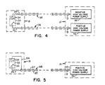
- Figure 4 illustrates a third embodiment in the present invention in which the high voltage anode cable 36 is electrically coupled to the anode 32 by a first series resistor 52 and the high voltage cathode cable 38 is electrically coupled to the cathode assembly 34 by a second series resistor 54.
- the sum of the resistance of resistors 52 and 54 is substantially equal to twice the characteristic impedance of the two high voltage cables, since during X-ray tube breakdown, they are electrically in series.
- a special case of the present invention utilizes a high voltage generator 12 which has a positive (with respect to ground) high voltage power supply 42, but does not include the negative power supply 44 of the previous embodiments.
- the positive high voltage power supply 42 is connected to a central conductor 57 of a high voltage cable 58 at the supply terminal 43.
- the central conductor 57 is coupled to the X-ray tube anode 32 by a series resistor 55 having a resistance substantially equal to the characteristic impedance of the high voltage cable 58.
- the cathode assembly 23 is held at essentially ground potential by a connection 56 to the grounded shield 59 of cable 58.
- resistor 55 may be varied in a manner similar to the embodiments in Figures 2-4. Specifically, resistor 55 can be connected to the cathode assembly 34 as part of connection 56, or separate resistors whose summed resistance equals the characteristic impedance of the cable 58 can be connected in at both the cathode and the anode.
- Each of the embodiments of the present invention places a resistance between the high voltage cable (or cables) and the X-ray tube.
- the value of this resistance is selected to optimally depress tube breakdown current.
- the number of high voltage cables determines the optimum value of the resistance.
- the optimum resistance is substantially twice the characteristic impedance of the two cables (36 and 38).
- the optimum transient depression resistance is equal to the characteristic impedance of the cable.
- transient depression resistive element e.g. resistor 40
- Both waveforms represent the tube breakdown through a high current arc between two sixty foot long high voltage anode and cathode cables 36 and 38 each having a characteristic impedance of 42 ohms and connected as shown in Figure 2.
- the waveform in Figure 6 illustrates the typical breakdown current oscillations that propagate between cables 36 and 38 through an X-ray tube assembly 18 without a resistor 40.
- a relatively small current flows through the tube from the anode 32 to the cathode assembly 34 (electrons flow from the cathode assembly 34 to the anode 32).
- Figure 7 depicts the breakdown current under the same conditions as represented in Figure 6, except for the insertion of an 84 ohm resistance between and in series with the high voltage cables 36 and 38 and the X-ray tube 30, as shown by the circuit of Figure 2.
- This resistance is twice the characteristic impedance (42 ohms) of the cables.
- the illustrative system of the present invention provides a twofold benefit by first reducing the peak current that flows through the X-ray tube 30 and secondly by preventing the oscillation between the high voltage cables. These benefits in turn, prolong the life of the X-ray tube.
- the resistive element should have a resistance which is substantially equal to twice the characteristic impedance of the cable when the anode and cathode voltage conductors are enclosed by separate shields.
- a transient suppression resistance substantially equal to the cable's characteristic impedance provides breakdown current protection. If a resistor cannot be found at the exact optimum resistance, a resistor having close to the optimum resistance can be employed.
- the instant transient suppression approach can be applied to other types of electronic devices.
- an electronic device such as a klystron, thyratron or even a solid state switch
- higher than normal currents may occur as a result of momentary device failure or a failure in an associated circuit component.
- the useful life of the electronic device can be severely curtailed, and may warrant the inclusion of the transient suppression suggested here.
- the voltage may not be particularly high, but impedance-matched current suppression would be especially effective.
Landscapes
- Engineering & Computer Science (AREA)
- Microelectronics & Electronic Packaging (AREA)
- Health & Medical Sciences (AREA)
- General Health & Medical Sciences (AREA)
- Toxicology (AREA)
- X-Ray Techniques (AREA)
Applications Claiming Priority (2)
| Application Number | Priority Date | Filing Date | Title |
|---|---|---|---|
| US417353 | 1989-10-05 | ||
| US07/417,353 US5008912A (en) | 1989-10-05 | 1989-10-05 | X-ray tube high voltage cable transient suppression |
Publications (3)
| Publication Number | Publication Date |
|---|---|
| EP0421720A2 true EP0421720A2 (fr) | 1991-04-10 |
| EP0421720A3 EP0421720A3 (en) | 1991-10-16 |
| EP0421720B1 EP0421720B1 (fr) | 1995-05-24 |
Family
ID=23653648
Family Applications (1)
| Application Number | Title | Priority Date | Filing Date |
|---|---|---|---|
| EP90310755A Expired - Lifetime EP0421720B1 (fr) | 1989-10-05 | 1990-10-02 | Suppression de transitoires dans des câbles |
Country Status (4)
| Country | Link |
|---|---|
| US (1) | US5008912A (fr) |
| EP (1) | EP0421720B1 (fr) |
| JP (1) | JP2599816B2 (fr) |
| DE (1) | DE69019663T2 (fr) |
Cited By (6)
| Publication number | Priority date | Publication date | Assignee | Title |
|---|---|---|---|---|
| EP0491519A1 (fr) * | 1990-12-18 | 1992-06-24 | General Electric Company | Système pour l'élimination du bruit transitoire d'un tube à rayons X |
| WO1992010921A1 (fr) * | 1990-12-06 | 1992-06-25 | Maxwell Laboratories, Inc. | Resistance de protection haute tension |
| EP0497517A1 (fr) * | 1991-01-30 | 1992-08-05 | General Electric Company | Méthode de purification d'un tube à vide pour le rayonnement des rayons X |
| US5229743A (en) * | 1990-12-06 | 1993-07-20 | Maxwell Laboratories, Inc. | High voltage protection resistor |
| EP0592164A1 (fr) * | 1992-10-06 | 1994-04-13 | Picker International, Inc. | Alimentations de puissance |
| WO2004064458A3 (fr) * | 2003-01-09 | 2004-09-16 | Siemens Ag | Alimentation haute tension pour un dispositif a rayons x |
Families Citing this family (10)
| Publication number | Priority date | Publication date | Assignee | Title |
|---|---|---|---|---|
| DE3929402A1 (de) * | 1989-09-05 | 1991-03-07 | Philips Patentverwaltung | Roentgeneinrichtung |
| DE19536247C2 (de) * | 1995-09-28 | 1999-02-04 | Siemens Ag | Röntgenröhre |
| US8571179B2 (en) * | 1999-11-10 | 2013-10-29 | Robert Beland | Computed tomography systems |
| US6738275B1 (en) * | 1999-11-10 | 2004-05-18 | Electromed Internationale Ltee. | High-voltage x-ray generator |
| US6452477B1 (en) | 2000-09-06 | 2002-09-17 | Marconi Medical Systems, Inc. | High voltage low inductance circuit protection resistor |
| US6882703B2 (en) * | 2002-07-31 | 2005-04-19 | Ge Medical Systems Global Technology Company, Llc | Electron source and cable for x-ray tubes |
| US7668295B2 (en) * | 2007-05-14 | 2010-02-23 | General Electric Co. | System and method for high voltage transient suppression and spit protection in an x-ray tube |
| KR101966794B1 (ko) * | 2017-07-12 | 2019-08-27 | (주)선재하이테크 | 전자 집속 개선용 엑스선관 |
| DE102024107501A1 (de) * | 2024-03-15 | 2025-09-18 | Esspen Gmbh | Röntgenröhre und Verfahren zum Betrieb einer Röntgenröhre |
| US12621919B2 (en) * | 2024-08-21 | 2026-05-05 | Fisica, Inc. | Short pulse X-ray generator |
Family Cites Families (21)
| Publication number | Priority date | Publication date | Assignee | Title |
|---|---|---|---|---|
| DE393871C (de) * | 1921-08-09 | 1924-04-16 | C H F Mueller Spezialfabrik Fu | Einrichtung zur Daempfung von UEberspannungswellen in Roentgenanlagen mit in die Zufuehrungsleitung eingeschalteten Widerstaenden |
| US1645643A (en) * | 1926-10-21 | 1927-10-18 | Herman Jakobsson | Nongrounded transmission line |
| US3069548A (en) * | 1958-12-17 | 1962-12-18 | Machlett Lab Inc | Protective circuits for electron tubes |
| US3197719A (en) * | 1961-02-13 | 1965-07-27 | Rca Corp | Impedance matching source to line for pulse frequencies without attenuating zero frequency |
| US3325645A (en) * | 1964-08-11 | 1967-06-13 | Picker X Ray Corp Waite Mfg | X-ray tube system with voltage and current control means |
| US3636355A (en) * | 1969-09-24 | 1972-01-18 | Cgr Medical Corp | Starting voltage suppressor circuitry for an x-ray generator |
| US3668465A (en) * | 1971-02-16 | 1972-06-06 | Seaco Computer Display Inc | Surge voltage protection for cathode ray tube drivers |
| DE2402125A1 (de) * | 1974-01-15 | 1975-07-24 | Siemens Ag | Gleichspannunguebertragungsanlage |
| DE2719373C2 (de) * | 1977-04-30 | 1982-10-21 | Philips Patentverwaltung Gmbh, 2000 Hamburg | Schaltungsanordnung eines Röntgengenerators mit einem durch ein Zeitsteuerglied gesteuerten elektronischen Schalter im Primärkreis eines Hochspannungs-Transformators |
| US4172269A (en) * | 1977-12-19 | 1979-10-23 | North American Philips Corporation | Circuit for overshoot supression in X-ray generators |
| DE2802451A1 (de) * | 1978-01-20 | 1979-07-26 | Siemens Ag | Roentgendiagnostikgenerator |
| DE2917636A1 (de) * | 1979-05-02 | 1980-11-13 | Philips Patentverwaltung | Roentgengenerator |
| US4288700A (en) * | 1979-10-22 | 1981-09-08 | General Electric Company | Cable handling device for diagnostic x-ray apparatus |
| JPS6025341A (ja) * | 1983-07-22 | 1985-02-08 | Hitachi Ltd | 遠隔監視装置 |
| JPS61263100A (ja) * | 1985-05-17 | 1986-11-21 | Hitachi Ltd | X線装置の電流測定装置 |
| JPS634599A (ja) * | 1986-06-25 | 1988-01-09 | Toshiba Corp | X線装置 |
| DE3639088A1 (de) * | 1986-11-14 | 1988-05-26 | Siemens Ag | Schaltungsanordnung mit einem schutzwiderstand zur strombegrenzung bei roentgenstrahlern |
| US4704630A (en) * | 1986-11-18 | 1987-11-03 | Rca Corporation | Wide bandwidth display driver apparatus |
| JPH0616479Y2 (ja) * | 1987-12-25 | 1994-04-27 | 横河メディカルシステム株式会社 | X線発生装置 |
| DE8807359U1 (de) * | 1988-06-06 | 1989-10-12 | Siemens AG, 1000 Berlin und 8000 München | Röntgenstrahler |
| DE3929402A1 (de) * | 1989-09-05 | 1991-03-07 | Philips Patentverwaltung | Roentgeneinrichtung |
-
1989
- 1989-10-05 US US07/417,353 patent/US5008912A/en not_active Expired - Lifetime
-
1990
- 1990-10-02 DE DE69019663T patent/DE69019663T2/de not_active Expired - Fee Related
- 1990-10-02 EP EP90310755A patent/EP0421720B1/fr not_active Expired - Lifetime
- 1990-10-04 JP JP2265314A patent/JP2599816B2/ja not_active Expired - Fee Related
Cited By (8)
| Publication number | Priority date | Publication date | Assignee | Title |
|---|---|---|---|---|
| WO1992010921A1 (fr) * | 1990-12-06 | 1992-06-25 | Maxwell Laboratories, Inc. | Resistance de protection haute tension |
| US5229743A (en) * | 1990-12-06 | 1993-07-20 | Maxwell Laboratories, Inc. | High voltage protection resistor |
| EP0491519A1 (fr) * | 1990-12-18 | 1992-06-24 | General Electric Company | Système pour l'élimination du bruit transitoire d'un tube à rayons X |
| EP0497517A1 (fr) * | 1991-01-30 | 1992-08-05 | General Electric Company | Méthode de purification d'un tube à vide pour le rayonnement des rayons X |
| EP0592164A1 (fr) * | 1992-10-06 | 1994-04-13 | Picker International, Inc. | Alimentations de puissance |
| US5347571A (en) * | 1992-10-06 | 1994-09-13 | Picker International, Inc. | X-ray tube arc suppressor |
| WO2004064458A3 (fr) * | 2003-01-09 | 2004-09-16 | Siemens Ag | Alimentation haute tension pour un dispositif a rayons x |
| US7110499B2 (en) | 2003-01-09 | 2006-09-19 | Siemens Aktiengesellschaft | High-voltage supply for an X-ray device |
Also Published As
| Publication number | Publication date |
|---|---|
| DE69019663D1 (de) | 1995-06-29 |
| JPH03171597A (ja) | 1991-07-25 |
| EP0421720A3 (en) | 1991-10-16 |
| DE69019663T2 (de) | 1996-03-07 |
| US5008912A (en) | 1991-04-16 |
| EP0421720B1 (fr) | 1995-05-24 |
| JP2599816B2 (ja) | 1997-04-16 |
Similar Documents
| Publication | Publication Date | Title |
|---|---|---|
| US5008912A (en) | X-ray tube high voltage cable transient suppression | |
| US5132999A (en) | Inductive x-ray tube high voltage transient suppression | |
| EP0592164B1 (fr) | Alimentations de puissance | |
| US5056125A (en) | Discharge module for X-ray cable | |
| US7668295B2 (en) | System and method for high voltage transient suppression and spit protection in an x-ray tube | |
| US5159697A (en) | X-ray tube transient noise suppression system | |
| US3808559A (en) | Modulator system | |
| US5077770A (en) | High voltage capacitance discharge system for x-ray tube control circuits | |
| EP0009409A1 (fr) | Protection contre les décharges disruptives dans les tubes à rayons cathodiques | |
| US20080089482A1 (en) | X-ray apparatus | |
| JPS5854600A (ja) | X−線発生器 | |
| US5159618A (en) | X-ray tube enclosure with resistive coating | |
| US4559640A (en) | X-Ray tube cathode multiple polarization device and a radiation source incorporating such a device | |
| US3938001A (en) | Protection circuit for electron gun | |
| JPH10106793A (ja) | パルスx線装置 | |
| US3921078A (en) | Breakdown protection for field emission electron gun | |
| US20060078088A1 (en) | X-ray Tube Cathode Overvoltage Transient Supression Apparatus | |
| US4600859A (en) | Cathode ray tube protection systems | |
| US20250120004A1 (en) | Cathode supply assembly | |
| JPH0616479Y2 (ja) | X線発生装置 | |
| JP3357553B2 (ja) | 高電圧発生fegタンク | |
| KR0138973Y1 (ko) | 정전기를 방지하는 음극선관 | |
| Kerns et al. | Spark-Gap-Trigger Amplifier | |
| JPS60167630A (ja) | 大電力イオン源装置の電源システム | |
| JPH11122948A (ja) | 高周波インバータ装置 |
Legal Events
| Date | Code | Title | Description |
|---|---|---|---|
| PUAI | Public reference made under article 153(3) epc to a published international application that has entered the european phase |
Free format text: ORIGINAL CODE: 0009012 |
|
| AK | Designated contracting states |
Kind code of ref document: A2 Designated state(s): DE FR GB NL |
|
| PUAL | Search report despatched |
Free format text: ORIGINAL CODE: 0009013 |
|
| AK | Designated contracting states |
Kind code of ref document: A3 Designated state(s): DE FR GB NL |
|
| 17P | Request for examination filed |
Effective date: 19911220 |
|
| 17Q | First examination report despatched |
Effective date: 19930225 |
|
| GRAA | (expected) grant |
Free format text: ORIGINAL CODE: 0009210 |
|
| AK | Designated contracting states |
Kind code of ref document: B1 Designated state(s): DE FR GB NL |
|
| ET | Fr: translation filed | ||
| REF | Corresponds to: |
Ref document number: 69019663 Country of ref document: DE Date of ref document: 19950629 |
|
| PLBE | No opposition filed within time limit |
Free format text: ORIGINAL CODE: 0009261 |
|
| STAA | Information on the status of an ep patent application or granted ep patent |
Free format text: STATUS: NO OPPOSITION FILED WITHIN TIME LIMIT |
|
| 26N | No opposition filed | ||
| REG | Reference to a national code |
Ref country code: GB Ref legal event code: IF02 |
|
| PGFP | Annual fee paid to national office [announced via postgrant information from national office to epo] |
Ref country code: NL Payment date: 20030919 Year of fee payment: 14 |
|
| PGFP | Annual fee paid to national office [announced via postgrant information from national office to epo] |
Ref country code: GB Payment date: 20030924 Year of fee payment: 14 |
|
| PGFP | Annual fee paid to national office [announced via postgrant information from national office to epo] |
Ref country code: FR Payment date: 20031020 Year of fee payment: 14 |
|
| PGFP | Annual fee paid to national office [announced via postgrant information from national office to epo] |
Ref country code: DE Payment date: 20031201 Year of fee payment: 14 |
|
| PG25 | Lapsed in a contracting state [announced via postgrant information from national office to epo] |
Ref country code: GB Free format text: LAPSE BECAUSE OF NON-PAYMENT OF DUE FEES Effective date: 20041002 |
|
| PG25 | Lapsed in a contracting state [announced via postgrant information from national office to epo] |
Ref country code: NL Free format text: LAPSE BECAUSE OF NON-PAYMENT OF DUE FEES Effective date: 20050501 |
|
| PG25 | Lapsed in a contracting state [announced via postgrant information from national office to epo] |
Ref country code: DE Free format text: LAPSE BECAUSE OF NON-PAYMENT OF DUE FEES Effective date: 20050503 |
|
| GBPC | Gb: european patent ceased through non-payment of renewal fee |
Effective date: 20041002 |
|
| PG25 | Lapsed in a contracting state [announced via postgrant information from national office to epo] |
Ref country code: FR Free format text: LAPSE BECAUSE OF NON-PAYMENT OF DUE FEES Effective date: 20050630 |
|
| NLV4 | Nl: lapsed or anulled due to non-payment of the annual fee |
Effective date: 20050501 |
|
| REG | Reference to a national code |
Ref country code: FR Ref legal event code: ST |