EP0422446A2 - Equipement pour véhicule à moteur - Google Patents
Equipement pour véhicule à moteur Download PDFInfo
- Publication number
- EP0422446A2 EP0422446A2 EP90118449A EP90118449A EP0422446A2 EP 0422446 A2 EP0422446 A2 EP 0422446A2 EP 90118449 A EP90118449 A EP 90118449A EP 90118449 A EP90118449 A EP 90118449A EP 0422446 A2 EP0422446 A2 EP 0422446A2
- Authority
- EP
- European Patent Office
- Prior art keywords
- cover
- housing
- equipment according
- articulated
- equipment
- Prior art date
- Legal status (The legal status is an assumption and is not a legal conclusion. Google has not performed a legal analysis and makes no representation as to the accuracy of the status listed.)
- Granted
Links
Images

Classifications
-
- B—PERFORMING OPERATIONS; TRANSPORTING
- B60—VEHICLES IN GENERAL
- B60J—WINDOWS, WINDSCREENS, NON-FIXED ROOFS, DOORS, OR SIMILAR DEVICES FOR VEHICLES; REMOVABLE EXTERNAL PROTECTIVE COVERINGS SPECIALLY ADAPTED FOR VEHICLES
- B60J3/00—Antiglare equipment associated with windows or windscreens; Sun visors for vehicles
- B60J3/02—Antiglare equipment associated with windows or windscreens; Sun visors for vehicles adjustable in position
- B60J3/0204—Sun visors
- B60J3/0278—Sun visors structure of the body
- B60J3/0282—Sun visors structure of the body specially adapted for a courtesy mirror
Definitions
- the invention relates to a conversion part for vehicles of the kind mentioned in the preamble of claims 1 and 2.
- Equipment parts for vehicles which consist of a box-shaped housing with a cover arranged thereon or equipment parts for vehicles which are equipped with a box-shaped housing and a cover arrangement, are known for various purposes and in various embodiments.
- the box-shaped housings are used, for example, to hold utensils of all kinds or in particular also to hold mirrors for make-up purposes.
- the box-shaped housings are often also equipped with a lighting device in order to find the utensils housed therein even in the dark or to be able to use a mirror even in the dark.
- the box-shaped housings are provided with a pivotable cover fastened to an axis, which is pivoted towards and away from the housing and thereby takes up a relatively large amount of opening space (cf., for example, DE-OS 26 31 712).
- equipment parts are known that are equipped with a sliding cover, but often not is desirable, especially since a sliding cover takes up a relatively large amount of opening space and requires guides that inevitably enlarge the box-shaped housing (see, for example, DE-OS 33 24 169).
- the present invention has for its object to improve an equipment part of the type mentioned in terms of the lid arrangement and to provide an equipment part for vehicles that contributes to the comfort and convenience of passengers and the attractiveness of the vehicle interior.
- the measures according to the invention have created a further vehicle equipment part which offers an additional increase in utility and attractiveness, is practical to handle and aesthetically appealing.
- a smaller opening space is required for the cover than for a cover that can be pivoted outwards via an axis or that for a cover that can be moved outwards via guides.
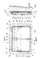
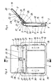
- an equipment part for vehicles which consists essentially of a box-shaped housing 1, a cover 2 and an opening mechanism to be described in more detail.
- the housing 1 has an essentially rectangular basic shape and, seen in relation to the drawing, has an upper housing wall 3, a lower housing wall 4, side walls 5 and a bottom 6.
- the walls 3 to 5 merge into a circumferential flange 7.
- In the bottom 6 there is a window-like opening 8 in which a mirror 9 is inserted.
- the mirror 9 is held in a receiving groove 10 and molded-on clip strips 11 on the housing 1.
- the side walls 5 are formed with link guides 12 in the form of slide grooves which extend almost over the entire length of the side walls 5 and have extensions 13 in the lower end region.
- the housing 1 also has slot openings 14 provided in the upper side wall 3 thereof.
- bearing receptacles 17 which - as shown in FIG. 4 - can be designed as bearing eyes.
- fastening projections 15 are formed, each of which carries a spring 16, which is expediently designed as a leaf spring. 4 shows one of the springs 16, which engage in the link guide 12, once with a solid line, which represents the relaxed spring position, and once with a broken line, which represents the tensioned spring position.
- the upper housing wall 3 of the housing 1 has locking pegs 18 formed on the lateral end regions, which protrude slightly into the interior of the housing.
- the cover 2 which is intended to expose the housing 1 on the housing opening side in a closed position at least in regions (FIGS. 3 and 4), has a flat plate shape with a (preferably) circumferential plate edge 19. Openings 20 are recessed in the upper plate edge area running parallel to the upper housing wall 3 of the housing 1, into which the locking pins 18 snap when the cover 2 is in its closed position. as can be seen particularly clearly from FIG. 2.
- the cover 2 In its lower edge region, the cover 2 furthermore has two guide pins 21, which run parallel to it and project beyond the lateral cover edges and find a sliding arrangement in the link guides 12.
- the cover 2 has bearing eyes 22 formed on the rear with a bearing receptacle 23, which, as shown, can be round or, depending on the desired opening angle of the cover 2, elongated.
- the lid 2 is formed on its rear side, approximately in the middle of the lid, with a hanging pin 24 formed thereon for one end of an opening spring 25.
- the cover 2 is connected to the housing 1 both on the one hand via the guide pins 21 and on the other hand via a joint body 26 so that it can slide and swivel.
- the joint body 26, which is expediently designed as a plastic injection-molded part, has an approximately H-shaped configuration, as seen in plan view (see FIG. 1).
- the free end regions of the vertically aligned H-legs are equipped with upper journals 27 and lower journals 28, it being possible to form the journals 27, 28 in one piece with the joint body 26.
- the upper areas of the vertically aligned H-legs are guided through the slot openings 14 in the upper housing wall 3 of the housing and the upper bearing pins 27 engage in the bearing receptacles 17 of the housing, so that the joint body 26 is pivotally connected to the housing 1.
- the joint body 26 is also pivotally connected to the cover 2 by the lower bearing pins 28 engaging the same in the bearing receptacles 23 of the cover 2. If a vertical cut is made through the joint body 26 at the height of the bearing journals 27 and 28, one can see a crutch-like or approximately P-shaped cross-sectional configuration of the same with an open P-arm (cf. in particular FIG. 2). Both the free end of the P-leg and the free end of the P-arm each form a bearing journal 27 or 28.
- Each P-arm is designed in some areas as a support web 29, which is in the closed cover position on a rear flange rib 30 Can support housing 1. Additionally or alternatively, a support body 31 can also be provided, which is to be arranged or molded on the bottom 6 of the housing 1 or on the joint body 26.
- the articulated body 26 consists in its central region (horizontal H-leg) of a bridge part 32 and of an axis 33, the latter serving to hang in the second end of the opening spring 25.
- the opening spring 25 is a tension spring, for which purpose a helical spring is expediently used, although it is also conceivable to use an elastic band or the like.
- the opening spring 25 is tensioned when the cover 2 is transferred from its open position to the closed position, which can be brought about by light pressure on the upper edge of the cover.
- the guide pins 21 then slide from top to bottom through the link guide 12 and tension the spring 16 in the last phase of the movement stroke.
- the joint body 26 is moved from its pivoted-out position (FIG. 4) to its pivoted-in position (FIG.
- the locking of the cover 2 can be released by slightly pushing (tapping) the cover 2 against the force of the springs 16 which, like the guide pins 21, penetrate into the extensions 13 of the link guides 12.
- the lid 2 can thus be opened via an automatic typing system, the tension spring 25 taking over the opening movement after the locking has been released. So that the spring 25 is not hindered in its work, the bridge part 32 is arched out of the plane of the joint body 26.
- the opening movement is completed when the cover 2 assumes its position shown in FIG. 4 (the opening angle here is approximately 135 degrees). Of course, other angular positions (smaller or larger) are also possible for the opened cover 2.
- damping or braking means can be provided in the area of the joint designs 17, 27, for example.
- measures can be taken to increase friction or small fat brakes can be installed.
- stop buffers 34 (FIG. 4), which may be made of felt or another damping material, are arranged between the surfaces of the cover and of the joint body 26 which are adjacent to one another in the open position of the cover 2.
- the box-shaped housing 1 is equipped with a mirror 9. So that the mirror 9 can also be used in the dark, the housing 1 preferably includes a lighting device, not shown.
- Fig. 3 it is indicated that 9 light windows 35 can be installed next to the mirror, under which there are electrical light sources 36, for example, festoon lamps.
- the light windows made of translucent material can be arranged offset in height from the mirror 9 in the housing 1.
- a commercially available battery, which can be interchangeably arranged in the housing 1, can serve, for example, for the electrical power supply of the light sources 36.
- FIG. 5 shows a vehicle equipment part in the form of a sun visor 37, which is equipped with an equipment part as has been explained in detail above with reference to FIGS. 1 to 4.
- the sun visor 37 has, on the broad side facing the viewer, a recess 38 in which the housing 1 can be arranged and fastened in such a way that the cover 2 is flush or almost flush with the outer surface of the sun visor 37.
- the electrical power supply can be provided by the general vehicle electronics.
- electrical conductors 39, 40 are embedded in the sun visor body, which are connected to the plus and ground and to the light sources.
- the electrical conductors can be guided through the main axis 41 and / or through the counter bearing axis 42 of the sun visor 37.
- To the Switching the light sources on and off can be provided in the individual switches, not shown, which can be actuated by the pivoting movement of the sun visor 37 and / or by the opening / closing movement of the cover 2 and / or manually.
- FIG. 6 shows a vehicle equipment part in the form of a headrest 43, which - like the sun visor 37 according to FIG. 5 - is equipped with an equipment part, as has been explained in detail above with reference to FIGS. 1 to 4.
- 7 shows a similar situation in the case of a vehicle equipment part in the form of a console 44.
- Fig. 7 is also indicated by pressure points 46 that it is easily possible to open the lid 2 either to the left, right, up or down. Of course, this possibility also exists with the piece of equipment as shown in FIGS. 1 to 6.
Landscapes
- Engineering & Computer Science (AREA)
- Mechanical Engineering (AREA)
- Vehicle Step Arrangements And Article Storage (AREA)
- Mounting, Exchange, And Manufacturing Of Dies (AREA)
- Fittings On The Vehicle Exterior For Carrying Loads, And Devices For Holding Or Mounting Articles (AREA)
Applications Claiming Priority (2)
| Application Number | Priority Date | Filing Date | Title |
|---|---|---|---|
| DE3933946A DE3933946A1 (de) | 1989-10-11 | 1989-10-11 | Ausruestungsteil fuer fahrzeuge |
| DE3933946 | 1989-10-11 |
Publications (3)
| Publication Number | Publication Date |
|---|---|
| EP0422446A2 true EP0422446A2 (fr) | 1991-04-17 |
| EP0422446A3 EP0422446A3 (en) | 1991-07-03 |
| EP0422446B1 EP0422446B1 (fr) | 1993-11-24 |
Family
ID=6391266
Family Applications (1)
| Application Number | Title | Priority Date | Filing Date |
|---|---|---|---|
| EP90118449A Expired - Lifetime EP0422446B1 (fr) | 1989-10-11 | 1990-09-26 | Equipement pour véhicule à moteur |
Country Status (4)
| Country | Link |
|---|---|
| EP (1) | EP0422446B1 (fr) |
| JP (1) | JPH07106694B2 (fr) |
| DE (2) | DE3933946A1 (fr) |
| ES (1) | ES2046643T3 (fr) |
Cited By (6)
| Publication number | Priority date | Publication date | Assignee | Title |
|---|---|---|---|---|
| DE4440606A1 (de) * | 1994-11-14 | 1996-05-15 | Happich Gmbh Gebr | Sonnenblende für Fahrzeuge |
| DE19737346A1 (de) * | 1997-08-27 | 1999-03-04 | Happich Gmbh Gebr | Sonnenblende für Fahrzeuge |
| DE102005006531B4 (de) * | 2005-02-11 | 2007-10-18 | Knorr-Bremse Systeme für Schienenfahrzeuge GmbH | Bewegungskulisse, Deckel und Gehäuse |
| DE19932298B4 (de) * | 1998-07-16 | 2008-07-31 | Volkswagen Ag | Kopfstütze mit Make-up-Spiegel |
| WO2012097992A1 (fr) * | 2011-01-20 | 2012-07-26 | Johnson Controls Interiors Gmbh & Co. Kg | Dispositif de déplacement pour un élément d'équipement intérieur de véhicule automobile et élément d'équipement intérieur |
| RU2474473C1 (ru) * | 2011-09-16 | 2013-02-10 | Российская Федерация, От Имени Которой Выступает Министерство Промышленности И Торговли Российской Федерации | КАТАЛИЗАТОР, СПОСОБ ЕГО ПРИГОТОВЛЕНИЯ И СПОСОБ ПОЛУЧЕНИЯ β-ПИКОЛИНА |
Families Citing this family (5)
| Publication number | Priority date | Publication date | Assignee | Title |
|---|---|---|---|---|
| DE4226251C2 (de) * | 1992-08-08 | 1996-08-01 | Happich Gmbh Gebr | Sonnenblende für Fahrzeuge |
| DE9312890U1 (de) * | 1993-08-27 | 1993-11-04 | J.C.F. Kaufmann Metallwarenwerk GmbH & Co. KG, 42327 Wuppertal | Behälteraufbau, insbesondere Abfallbehälter in Schienenfahrzeugen |
| DE9401228U1 (de) * | 1994-01-25 | 1995-06-01 | Eldra-Kunststofftechnik GmbH, 84144 Geisenhausen | Deckelverriegelung für die Abdeckung von Behältnissen in Kraftfahrzeugen |
| DE19519507C2 (de) * | 1995-05-31 | 1997-05-22 | Butz Peter Verwaltung | Transportvorrichtung, wie z. B. für Personen- oder Kombinationskraftwagen, mit einem Behälter für langgestrecktes Ladegut, wie z. B. für Skier |
| US12479345B2 (en) | 2023-03-03 | 2025-11-25 | GM Global Technology Operations LLC | Vehicle seat component having a storage zone and electronic device support |
Family Cites Families (15)
| Publication number | Priority date | Publication date | Assignee | Title |
|---|---|---|---|---|
| US2798632A (en) * | 1954-07-12 | 1957-07-09 | Gen Motors Corp | Ash tray assembly |
| GB1523398A (en) * | 1975-07-14 | 1978-08-31 | Prince Corp | Vehicle sun visor assembly incorporating a mirror |
| JPS54109241U (fr) * | 1978-01-13 | 1979-08-01 | ||
| DE2933036A1 (de) * | 1979-08-16 | 1981-03-26 | Gebr. Happich Gmbh, 42285 Wuppertal | Beleuchteter make-up spiegel fuer die verwendung im fahrzeug |
| FR2549787B3 (fr) * | 1983-07-30 | 1985-08-09 | Iveco Magirus | Boite vide-poche pour un vehicule a moteur |
| US4521051A (en) * | 1983-09-15 | 1985-06-04 | Prince Corporation | Visor with mirror and storage means |
| IT8422586U1 (it) * | 1984-07-16 | 1986-01-16 | Alfa Romeo Spa | Mobiletto con comandi e servi per una autovettura. |
| DE3432739A1 (de) * | 1984-09-06 | 1986-03-13 | Adam Opel AG, 6090 Rüsselsheim | Kraftfahrzeug |
| DE3445211A1 (de) * | 1984-12-12 | 1986-06-12 | Ford-Werke AG, 5000 Köln | Verstauvorrichtung innerhalb von verkleidungen in kraftfahrzeugen |
| DE3513293A1 (de) * | 1985-04-13 | 1986-10-16 | Gebr. Happich Gmbh, 5600 Wuppertal | Fahrzeugausruestungsteil, wie haltegriff, handschuhkastendeckel, ascher oder dergleichen |
| DE3535971A1 (de) * | 1985-10-09 | 1987-04-16 | Sidler Gmbh & Co | Vorrichtung zum abdecken einer oeffnung |
| DE3602197A1 (de) * | 1986-01-25 | 1987-07-30 | Opel Adam Ag | Ascher, insbesondere fuer kraftfahrzeuge |
| IT1209694B (it) * | 1986-03-12 | 1989-08-30 | Carlo Perego | Porta per autorimessa a basculamento interno. |
| DE3741164C1 (de) * | 1987-12-04 | 1989-07-20 | Airbus Gmbh | Gepaeckablage fuer Fahrzeuge,insbesondere Flugzeuge |
| JPH0637009Y2 (ja) * | 1988-07-01 | 1994-09-28 | デルタ工業株式会社 | 自動車用リッドの開閉装置 |
-
1989
- 1989-10-11 DE DE3933946A patent/DE3933946A1/de not_active Withdrawn
-
1990
- 1990-09-26 ES ES199090118449T patent/ES2046643T3/es not_active Expired - Lifetime
- 1990-09-26 EP EP90118449A patent/EP0422446B1/fr not_active Expired - Lifetime
- 1990-09-26 DE DE90118449T patent/DE59003598D1/de not_active Expired - Fee Related
- 1990-10-11 JP JP2270682A patent/JPH07106694B2/ja not_active Expired - Lifetime
Cited By (8)
| Publication number | Priority date | Publication date | Assignee | Title |
|---|---|---|---|---|
| DE4440606A1 (de) * | 1994-11-14 | 1996-05-15 | Happich Gmbh Gebr | Sonnenblende für Fahrzeuge |
| DE4440606C2 (de) * | 1994-11-14 | 2001-06-13 | Johnson Contr Interiors Gmbh | Sonnenblende für Fahrzeuge |
| DE19737346A1 (de) * | 1997-08-27 | 1999-03-04 | Happich Gmbh Gebr | Sonnenblende für Fahrzeuge |
| DE19932298B4 (de) * | 1998-07-16 | 2008-07-31 | Volkswagen Ag | Kopfstütze mit Make-up-Spiegel |
| DE102005006531B4 (de) * | 2005-02-11 | 2007-10-18 | Knorr-Bremse Systeme für Schienenfahrzeuge GmbH | Bewegungskulisse, Deckel und Gehäuse |
| WO2012097992A1 (fr) * | 2011-01-20 | 2012-07-26 | Johnson Controls Interiors Gmbh & Co. Kg | Dispositif de déplacement pour un élément d'équipement intérieur de véhicule automobile et élément d'équipement intérieur |
| CN103442914A (zh) * | 2011-01-20 | 2013-12-11 | 约翰逊内控两合公司 | 用于机动车内饰件的运动装置和内饰件 |
| RU2474473C1 (ru) * | 2011-09-16 | 2013-02-10 | Российская Федерация, От Имени Которой Выступает Министерство Промышленности И Торговли Российской Федерации | КАТАЛИЗАТОР, СПОСОБ ЕГО ПРИГОТОВЛЕНИЯ И СПОСОБ ПОЛУЧЕНИЯ β-ПИКОЛИНА |
Also Published As
| Publication number | Publication date |
|---|---|
| JPH03217353A (ja) | 1991-09-25 |
| DE59003598D1 (de) | 1994-01-05 |
| ES2046643T3 (es) | 1994-02-01 |
| EP0422446A3 (en) | 1991-07-03 |
| JPH07106694B2 (ja) | 1995-11-15 |
| DE3933946A1 (de) | 1991-04-18 |
| EP0422446B1 (fr) | 1993-11-24 |
Similar Documents
| Publication | Publication Date | Title |
|---|---|---|
| EP0096154B1 (fr) | Pare-soleil notamment pour véhicules | |
| DE4443521C1 (de) | Abdeckbarer Behälter für Fahrzeuge | |
| DE2607816C3 (de) | Windabweiseranordnung an einem Kraftfahrzeugdach | |
| DE4331884B4 (de) | Abdeckeinrichtung für einen Kosmetikspiegel | |
| DE69922901T2 (de) | Schnappscharnier zum Tragen von Türpaneelen | |
| EP0636069B1 (fr) | Retroviseur interieur avec vide-poches integre pour vehicules a moteur | |
| DE20102892U1 (de) | Telefonhalterung für ein Handy in einem Fahrzeug | |
| DE4326102A1 (de) | Spiegel mit Beleuchtungseinrichtung, insbesondere für Fahrzeuge | |
| EP1764266B1 (fr) | Console centrale pour un véhicule | |
| EP0764558A2 (fr) | Structure de montage pour véhicules | |
| EP0422446B1 (fr) | Equipement pour véhicule à moteur | |
| DE3404920A1 (de) | Helm mit schwenkbarem visier, insbesondere fuer sportzwecke | |
| EP2722231A1 (fr) | Dispositif de recouvrement d'un compartiment de rangement et dispositif de compartiment de rangement | |
| DE102004007489B4 (de) | Sonnenblende für ein Fahrzeug | |
| DE3518751C1 (de) | Sonnenblende fuer Fahrzeuge | |
| DE4337808A1 (de) | Sonnenblende für Fahrzeuge | |
| DE3113306A1 (de) | Kraftfahrzeugdach mit verschliessbarer dachoeffnung und windabweiser | |
| DE19724597C1 (de) | Mittelkonsole für ein Fahrzeug | |
| DE69600295T2 (de) | Vorrichtung zum Aufbewahren von Gegenständen, insbesondere in Kraftfahrzeugen | |
| DE19754832B4 (de) | Fahrzeugtür, insbesondere für Personenkraftwagen | |
| DE19535678A1 (de) | Autoradio mit schwenkbarem Bedienteil | |
| EP0755814A1 (fr) | Contre-support pour pare-soleil de véhicule | |
| DE10340079B4 (de) | Sonnenblende | |
| EP3787135A1 (fr) | Armoire de distribution | |
| EP4265480A1 (fr) | Ensemble couvercle de compartiment à bagages pour un véhicule, compartiment à bagages d'un véhicule et véhicule |
Legal Events
| Date | Code | Title | Description |
|---|---|---|---|
| PUAI | Public reference made under article 153(3) epc to a published international application that has entered the european phase |
Free format text: ORIGINAL CODE: 0009012 |
|
| AK | Designated contracting states |
Kind code of ref document: A2 Designated state(s): BE DE ES FR GB IT SE |
|
| PUAL | Search report despatched |
Free format text: ORIGINAL CODE: 0009013 |
|
| AK | Designated contracting states |
Kind code of ref document: A3 Designated state(s): BE DE ES FR GB IT SE |
|
| 17P | Request for examination filed |
Effective date: 19910612 |
|
| 17Q | First examination report despatched |
Effective date: 19920626 |
|
| GRAA | (expected) grant |
Free format text: ORIGINAL CODE: 0009210 |
|
| AK | Designated contracting states |
Kind code of ref document: B1 Designated state(s): BE DE ES FR GB IT SE |
|
| REF | Corresponds to: |
Ref document number: 59003598 Country of ref document: DE Date of ref document: 19940105 |
|
| ET | Fr: translation filed | ||
| REG | Reference to a national code |
Ref country code: ES Ref legal event code: FG2A Ref document number: 2046643 Country of ref document: ES Kind code of ref document: T3 |
|
| ITF | It: translation for a ep patent filed | ||
| GBT | Gb: translation of ep patent filed (gb section 77(6)(a)/1977) |
Effective date: 19940117 |
|
| PLBE | No opposition filed within time limit |
Free format text: ORIGINAL CODE: 0009261 |
|
| STAA | Information on the status of an ep patent application or granted ep patent |
Free format text: STATUS: NO OPPOSITION FILED WITHIN TIME LIMIT |
|
| 26N | No opposition filed | ||
| EAL | Se: european patent in force in sweden |
Ref document number: 90118449.9 |
|
| REG | Reference to a national code |
Ref country code: ES Ref legal event code: PC2A |
|
| REG | Reference to a national code |
Ref country code: FR Ref legal event code: CD |
|
| PGFP | Annual fee paid to national office [announced via postgrant information from national office to epo] |
Ref country code: FR Payment date: 19980810 Year of fee payment: 9 |
|
| PGFP | Annual fee paid to national office [announced via postgrant information from national office to epo] |
Ref country code: SE Payment date: 19980813 Year of fee payment: 9 |
|
| PGFP | Annual fee paid to national office [announced via postgrant information from national office to epo] |
Ref country code: GB Payment date: 19980819 Year of fee payment: 9 |
|
| PGFP | Annual fee paid to national office [announced via postgrant information from national office to epo] |
Ref country code: BE Payment date: 19980904 Year of fee payment: 9 |
|
| PGFP | Annual fee paid to national office [announced via postgrant information from national office to epo] |
Ref country code: ES Payment date: 19980907 Year of fee payment: 9 |
|
| PGFP | Annual fee paid to national office [announced via postgrant information from national office to epo] |
Ref country code: DE Payment date: 19990907 Year of fee payment: 10 |
|
| PG25 | Lapsed in a contracting state [announced via postgrant information from national office to epo] |
Ref country code: GB Free format text: LAPSE BECAUSE OF NON-PAYMENT OF DUE FEES Effective date: 19990926 |
|
| PG25 | Lapsed in a contracting state [announced via postgrant information from national office to epo] |
Ref country code: ES Free format text: LAPSE BECAUSE OF NON-PAYMENT OF DUE FEES Effective date: 19990927 |
|
| PG25 | Lapsed in a contracting state [announced via postgrant information from national office to epo] |
Ref country code: SE Free format text: THE PATENT HAS BEEN ANNULLED BY A DECISION OF A NATIONAL AUTHORITY Effective date: 19990929 |
|
| PG25 | Lapsed in a contracting state [announced via postgrant information from national office to epo] |
Ref country code: BE Free format text: LAPSE BECAUSE OF NON-PAYMENT OF DUE FEES Effective date: 19990930 |
|
| BERE | Be: lapsed |
Owner name: GEBR. HAPPICH G.M.B.H. Effective date: 19990930 |
|
| EUG | Se: european patent has lapsed |
Ref document number: 90118449.9 |
|
| GBPC | Gb: european patent ceased through non-payment of renewal fee |
Effective date: 19990926 |
|
| PG25 | Lapsed in a contracting state [announced via postgrant information from national office to epo] |
Ref country code: FR Free format text: LAPSE BECAUSE OF NON-PAYMENT OF DUE FEES Effective date: 20000531 |
|
| REG | Reference to a national code |
Ref country code: FR Ref legal event code: ST |
|
| PG25 | Lapsed in a contracting state [announced via postgrant information from national office to epo] |
Ref country code: DE Free format text: LAPSE BECAUSE OF NON-PAYMENT OF DUE FEES Effective date: 20010601 |
|
| REG | Reference to a national code |
Ref country code: ES Ref legal event code: FD2A Effective date: 20001013 |
|
| PG25 | Lapsed in a contracting state [announced via postgrant information from national office to epo] |
Ref country code: IT Free format text: LAPSE BECAUSE OF NON-PAYMENT OF DUE FEES;WARNING: LAPSES OF ITALIAN PATENTS WITH EFFECTIVE DATE BEFORE 2007 MAY HAVE OCCURRED AT ANY TIME BEFORE 2007. THE CORRECT EFFECTIVE DATE MAY BE DIFFERENT FROM THE ONE RECORDED. Effective date: 20050926 |