EP0423054A2 - Verfahren zur Herstellung von Druckplatten mit Hilfe eines Laserstrahls - Google Patents
Verfahren zur Herstellung von Druckplatten mit Hilfe eines Laserstrahls Download PDFInfo
- Publication number
- EP0423054A2 EP0423054A2 EP90610066A EP90610066A EP0423054A2 EP 0423054 A2 EP0423054 A2 EP 0423054A2 EP 90610066 A EP90610066 A EP 90610066A EP 90610066 A EP90610066 A EP 90610066A EP 0423054 A2 EP0423054 A2 EP 0423054A2
- Authority
- EP
- European Patent Office
- Prior art keywords
- laser
- magnetic coupling
- dampened
- laser beam
- polygonal mirror
- Prior art date
- Legal status (The legal status is an assumption and is not a legal conclusion. Google has not performed a legal analysis and makes no representation as to the accuracy of the status listed.)
- Granted
Links
- 238000007639 printing Methods 0.000 title claims abstract description 12
- 238000000034 method Methods 0.000 title claims abstract description 11
- 230000008878 coupling Effects 0.000 claims abstract description 20
- 238000010168 coupling process Methods 0.000 claims abstract description 20
- 238000005859 coupling reaction Methods 0.000 claims abstract description 20
- 239000010438 granite Substances 0.000 claims abstract description 6
- 239000000463 material Substances 0.000 claims abstract description 3
- 230000010355 oscillation Effects 0.000 claims abstract description 3
- 230000001846 repelling effect Effects 0.000 claims 1
- 238000012937 correction Methods 0.000 description 38
- XKRFYHLGVUSROY-UHFFFAOYSA-N Argon Chemical compound [Ar] XKRFYHLGVUSROY-UHFFFAOYSA-N 0.000 description 22
- 229910052786 argon Inorganic materials 0.000 description 11
- 230000010287 polarization Effects 0.000 description 5
- RYGMFSIKBFXOCR-UHFFFAOYSA-N Copper Chemical compound [Cu] RYGMFSIKBFXOCR-UHFFFAOYSA-N 0.000 description 4
- 238000004891 communication Methods 0.000 description 4
- 229910052802 copper Inorganic materials 0.000 description 4
- 239000010949 copper Substances 0.000 description 4
- 230000003287 optical effect Effects 0.000 description 4
- 239000010453 quartz Substances 0.000 description 4
- VYPSYNLAJGMNEJ-UHFFFAOYSA-N silicon dioxide Inorganic materials O=[Si]=O VYPSYNLAJGMNEJ-UHFFFAOYSA-N 0.000 description 4
- 239000013078 crystal Substances 0.000 description 3
- 238000004090 dissolution Methods 0.000 description 3
- 230000000694 effects Effects 0.000 description 1
- 239000011521 glass Substances 0.000 description 1
- 238000007645 offset printing Methods 0.000 description 1
- 230000005855 radiation Effects 0.000 description 1
Images


Classifications
-
- G—PHYSICS
- G03—PHOTOGRAPHY; CINEMATOGRAPHY; ANALOGOUS TECHNIQUES USING WAVES OTHER THAN OPTICAL WAVES; ELECTROGRAPHY; HOLOGRAPHY
- G03F—PHOTOMECHANICAL PRODUCTION OF TEXTURED OR PATTERNED SURFACES, e.g. FOR PRINTING, FOR PROCESSING OF SEMICONDUCTOR DEVICES; MATERIALS THEREFOR; ORIGINALS THEREFOR; APPARATUS SPECIALLY ADAPTED THEREFOR
- G03F7/00—Photomechanical, e.g. photolithographic, production of textured or patterned surfaces, e.g. printing surfaces; Materials therefor, e.g. comprising photoresists; Apparatus specially adapted therefor
- G03F7/20—Exposure; Apparatus therefor
- G03F7/2051—Exposure without an original mask, e.g. using a programmed deflection of a point source, by scanning, by drawing with a light beam, using an addressed light or corpuscular source
- G03F7/2053—Exposure without an original mask, e.g. using a programmed deflection of a point source, by scanning, by drawing with a light beam, using an addressed light or corpuscular source using a laser
- G03F7/2055—Exposure without an original mask, e.g. using a programmed deflection of a point source, by scanning, by drawing with a light beam, using an addressed light or corpuscular source using a laser for the production of printing plates; Exposure of liquid photohardening compositions
-
- B—PERFORMING OPERATIONS; TRANSPORTING
- B23—MACHINE TOOLS; METAL-WORKING NOT OTHERWISE PROVIDED FOR
- B23K—SOLDERING OR UNSOLDERING; WELDING; CLADDING OR PLATING BY SOLDERING OR WELDING; CUTTING BY APPLYING HEAT LOCALLY, e.g. FLAME CUTTING; WORKING BY LASER BEAM
- B23K26/00—Working by laser beam, e.g. welding, cutting or boring
- B23K26/08—Devices involving relative movement between laser beam and workpiece
- B23K26/082—Scanning systems, i.e. devices involving movement of the laser beam relative to the laser head
- B23K26/0821—Scanning systems, i.e. devices involving movement of the laser beam relative to the laser head using multifaceted mirrors, e.g. polygonal mirror
-
- B—PERFORMING OPERATIONS; TRANSPORTING
- B23—MACHINE TOOLS; METAL-WORKING NOT OTHERWISE PROVIDED FOR
- B23K—SOLDERING OR UNSOLDERING; WELDING; CLADDING OR PLATING BY SOLDERING OR WELDING; CUTTING BY APPLYING HEAT LOCALLY, e.g. FLAME CUTTING; WORKING BY LASER BEAM
- B23K26/00—Working by laser beam, e.g. welding, cutting or boring
- B23K26/08—Devices involving relative movement between laser beam and workpiece
- B23K26/083—Devices involving movement of the workpiece in at least one axial direction
- B23K26/0838—Devices involving movement of the workpiece in at least one axial direction by using an endless conveyor belt
- B23K26/0846—Devices involving movement of the workpiece in at least one axial direction by using an endless conveyor belt for moving elongated workpieces longitudinally, e.g. wire or strip material
-
- G—PHYSICS
- G02—OPTICS
- G02B—OPTICAL ELEMENTS, SYSTEMS OR APPARATUS
- G02B26/00—Optical devices or arrangements for the control of light using movable or deformable optical elements
- G02B26/08—Optical devices or arrangements for the control of light using movable or deformable optical elements for controlling the direction of light
- G02B26/10—Scanning systems
- G02B26/12—Scanning systems using multifaceted mirrors
- G02B26/121—Mechanical drive devices for polygonal mirrors
Definitions
- the invention relates to a method of producing printing plates by means of a laser beam, said laser beam being scanned by means of a rotating polygonal mirror.
- the object of the invention is to provide a method of producing offset printing plates by means of a scanning laser beam directly from text and picture information in a computer, where the scanning must be performed at a high speed and with a high accuracy.
- a method of the above type is according to the invention characterised by transferring the rotational movement to the polygonal mirror by means of a magnetic coupling, possible oscillations being dampened by a hysteresis-dampened, i.e. a faraday-dampened, magnetic coupling.
- the magnetic coupling is composed of intermeshing, radially projecting members comprising strong magnets disposed so as to repel one another and which can be slightly rotated relative to one another. In this manner a rotational accuracy of 6 ppm per rotation is obtained.
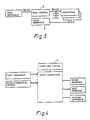
- FIG. 2 is a diagrammatic view of the laser exposure unit according to the invention.
- the laser exposure unit comprises a main control 2, a front end system 4, a clock-correction system 6 and a facet-correction system 8.
- the facet-correction system 8 communicates through a serial bus RS 422 with a machine control system 10, a control system 12 for the exposure plane, a beam expander control system 14, an argon laser system 16 and a polygon control system 18.
- the beam expander control system 14, the argon laser system 16 and the polygon control system 18 form part of an optical system also including an HeNe-laser system 20 controlling the clock-correction system 6 and the facet-correction system 8.
- the main control 2 performs the superior control of the entire system and controls all the submodules. In addition, the main control performs the external communication through the front end system 4.
- the clock-correction system 6 performs a correction so as to achieve an accuracy of the data flow to the printing plate to be exposed, a particular curving inside the machine necessitating a correction of the data in response to the position in the plane.
- the facet-correction system 8 corrects for errors in the reflecting facets of the polygonal mirror 32.
- the machine control system 10 performs the communication to current relays etc.
- the modules communicate with one another through a standard communication line RS 422 and software protocols.
- the control system 12 contrclling the exposure plane controls the movement of the exposing surface, i.e. the printing plate, by means of sensors.
- the optical system is controlled by electronic circuits.
- the beam expander system 14 controls the spot size of the pixels, and the argon laser 16 produces the laser beam exposing the printing plate.
- the laser beam from the HeNe-laser 20 is used for a clock correction and a facet correction.
- the laser exposing unit cannot operate as desired without the latter correcting beam.
- a user interface cf. Figure 3 communicates through an RS 232 bus with the main control 2 communicating internally through said RS 422 bus.
- a clock control 3 provides the necessary synchronising.
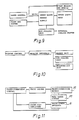
- the data must be corrected in order to allow the system to operate as planned, and for this purpose a clock-correction module is provided, cf. Figure 4.
- the data between a starting and a stopping detector are corrected on the basis of the clock frequency from the clock generator and the correction data from the clock-correction control so as to obtain a uniform distance between the pixels in the plane.
- the clock-correction system 6 modifies the serial bit-flow generated by means of the front end system 4 for mechanical errors.
- the correction is the sum of correction for geometrical errors, for dividing errors and for polygon errors.
- the clock correction causes a generation of adjusted clock signals for the front end interface, cf. Figure 5. These signals are called DATA CLK.
- the front end interface 6 a performs the external communication through a so-called IPU recoding data from other systems to a particular bit-flow suitable for exposure.
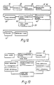
- the front end interface 6 a receives the bit-flow together with correction values from the clock-correction system 6 and transmits said data to an electro-optical modulator 36, cf. Figure 12.
- the electro-optical modulator modulates the exposure beam in response to the data information.
- the front end interface 6 a presents a datalink between IPU and the laser exposure unit.
- the data are transferred together with handshake signals to the interface through a databus of a bus width corresponding to one word.
- the interface 6 a adjusts the data to the correction data from the clock-correction system 6 and converts the corrected data into a serial bit-flow being transmitted to the modulator 36 for modulation of the exposure beam.
- the front end interface 6a also generates an external modulation signal for the argon laser system 16 based on the received handshake signals and status of the control system 12 for the exposure plane. Access to the control system 12 for the exposure plane is achieved through the exposuring plane interface.
- the polygon control system 18 controls the rotation of a rotating polygonal mirror 32 scanning lines on the offset plate.
- the polygon control system 18 communicates with the main control 2 through the serial bus RS 422.
- the main control 2 controls a driving motor 51 for the polygonal mirror 32 through a polygon interface 18 a .
- a power-dump in connection with the driving motor for the polygon can absorb energy generated during a decelleration.
- the polygon interface 18 a receives the reference clock signal for the driving motor 51, i.e. a stepmotor, from the clock generator, said clock signal being scaled down to the lower frequency.
- the driving system operates in a closed loop configuration, where a polygon encoder generates information on speed to the interface.
- a transducer detects the position of the polygon 32 and informs the clock-correction system so as to synchronize the correction with the position of the polygon.
- the stepmotor 51 is connected to a polygon/air bearing unit 53 through a hysteresis-dampened magnetic coupling, cf. Figure 17, ensuring a rotational accuracy of 6 ppm per rotation.
- the control system 12 for the exposure plane controls the movement of the exposure plane, i.e. the printing plate, by means of detectors and an encoder.
- the encoder provides an indication of the position and is an electronic unit optionally mounted on a shaft. Such a unit transmits a predetermined number of pulses per rotation; in the present case 1250 pulses per rotation, i.e. a dissolution of 1250 pulses.
- the pulses are transmitted to a counter to achieve an absolute indication of the position, said indication of the position being used for controlling the movement of the exposure plane.
- the control of the exposure plane is in turn controlled by the clock frequency from the system clock determining the superior speed of the system.
- the exposure plane rests on air bearings on a block of granite and is driven by a spindle system connected to an exposure plane motor and a DC motor.
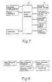
- the interface 6 b of the exposure plane interfaces the Z 80 exposure plane control and the clock generator with the exposure plane driving device 6 c and the DC motor driving device, cf. Figure 7.
- the interface generates information on the position of the exposure plane to the exposure plane control.
- the interface receives the signal scaled down from the clock-pulse generator and generates the control and clock signal for the exposure plane driving device 6 c and the DC motor driving device 6 d in response to the input signal from the exposure plane control.
- the exposure plane interface 6 b generates furthermore information on the position to the control on the basis of signals from the exposure plane encoder, autofocus, holding and starting position detectors.
- the exposure plane driving device 6 c controls the exposure plane motor during the exposure in a closed loop configuration while using the encoder feedback coupling and f-exp input. While moving quickly the DC motor takes over the control and decouples the exposure plane motor through a magnetic coupling not shown.
- the DC motor controls furthermore some detectors detecting movement errors.
- the beam expander control system 14 determines the spot size of the exposing beam.
- the spot size depends on the desired dissolution and the spot factor.
- the spot factor describes the overlapping during the scanning.
- the spot must overlap by a predetermined distance during a line scanning so as to achieve a uniform exposure of the plate.
- the overlapping corresponds to a distance of 10 microns between the scanning lines on the plate.
- the spot must be of a size exceeding 10 microns in order to ensure an overlapping.
- a suitable value is between a factor 2 to a factor 3, i.e. for the line distance of 10 microns the spot size corresponds to between 20 to 30 microns, which provides a uniform exposure as the resulting spots have a suitable overlapping.
- the beam expander 14 is an eight-position Galilean unit with a fixed focal plane.
- the expander comprises a revolving head 28 with eight different magnifying lenses.
- the argon laser 16 represents the actual light source for the exposure and communicates with a laser control through a serial bus.
- the laser control ensures that the argon laser 16 is driven by the desired power.
- the machine control system 10 forms the interface between the microprocessor and the heavy power signals.
- a vacuum pump retaining the printing plate to be exposed is for instance controlled by a machine interface converting 5 V signals into high-voltage signals for controlling purposes.
- the control system includes an HeNe-laser system 20 in connection with feedback loops.
- the feedback loops correct both facet errors and operation because the facet-correction detector 61 is displaced in response to the slow changes, i.e. follows the slow changes due to for instance thermal operation.
- the correction of slow changes is performed between two succeeding scannings so as not to interfere with the scanning. Facet errors are furthermore corrected.
- the facet-correction system 8 serves to correct errors and inaccuracies of the polygon facets.
- a facet-correction detector 61 is provided which generates a feedback signal.
- the feedback signal controls some piezoelectric transducers 30 a capable of changing the position of a facet-correction mirror 30 in the beam path in response to the error possibly appearing at any time. In this manner possible errors on the facets 32 of the polygon are eliminated, the line distance thereby being the same across the entire printing plate and for each facet.
- the laser beam from the argon laser 16 is transmitted through a separator 39 performing a choice of wavelength for the sake of the succeeding electrooptical modulator 36.
- the modulator 36 turns the laser beam on and off in response to the data-flow from the front end system 4.
- the modulated laser beam is deflected by means of two mirrors 41, 42 deflecting the beam and transmitting it through the beam expander 28.
- the laser beam is focused so as to achieve a suitable spot size on the printing plate to be exposed.
- the expanded output signal is mixed with the laser beam from the HeNe-laser 20 and reflected and redirected by means by the facet-correction mirror 30 in response to the output signal of the facet-correction system 8.
- the two beams are transmitted by means of the deflection mirror 43 to the active facet of the rotating polygon 32.
- the reflected exposuring beam sweeps the exposing surface while the reflected HeNe-laser beam is detected by means of start/stop detectors and the facet-correction detector 61 before it is blocked so as to avoid an incorrect exposure.
- the HeNe-laser system 20 is illustrated, said system transmitting a correcting beam almost parallel to the argon laser beam from the facet-correction mirror 30.
- the correcting beam is adapted to find the starting and stopping position of the plane and serves to correct errors in the facets of the polygon.
- Figure 14 illustrates the entire optical system and the argon laser 16 transmitting a laser beam to the separator 39.
- the separator 39 comprises two members, viz. a quartz block and a polarisator.
- the quartz block exhibits the ability that it differently turns the polarization of dissimilar wavelengths, i.e. when two light beams of wavelengths with the same polarization direction are transmitted, said light beams exit the crystal in dissimilar polarization directions.
- the latter ability of the quartz block is utilized for providing a quartz crystal of exactly the length ensuring that the polarization directions of the emitted wavelengths are turned 90° relative to one another.
- the laser beams transmitted in dissimilar polarization directions are separated by means of a polarisator 34 in form of a glass crystal with a dieelectric film of an angle of 45° relative to the direction of radiation.
- a polarisator 34 in form of a glass crystal with a dieelectric film of an angle of 45° relative to the direction of radiation.
- the straight beam is utilized and transmitted through a modulator 36 controlled by an electric signal so as to turn the beam on and off.
- Some mirrors deflect the beam and transmit said beam through the beam expander in form of a revolving head 28 with eight different lenses allowing the choice of the desired spot size.
- the revolving head 28 is turned in response to the desired spot size.
- the output signal of the beam expander 28 is transmitted to the facet-correction mirror 30 correcting possible polygonal errors.
- the reflecting mirror deflects the beam towards the polygon surface scanning the beam on the plane while rotating.
- the HeNe-laser 20 emits a laser beam hitting the facet-correction mirror 30 and the deflection mirror, and after a number of deflections the laser beam hits the polygon 32 and is emitted in a slightly different direction than the argon laser in such a manner that it can be detected by some starting and stopping detectors without interrupting the ultraviolet beam.
- the laser beam is received by the facet-correction detector 61 disposed in the middle.
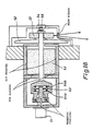
- Figure 17 illustrates the magnetic coupling comprlsing intermeshing, radially projecting members, which can be slightly rotated relative to one another. Strong magnets 62 are built in the opposing surfaces of these radially projecting members in such a manner that they repel one another during the transfer of a rotational movement.
- a hysteresis-dampened magnetic coupling is furthermore provided in connection with the magnetic coupling, said hysteresis-dampened magnetic coupling comprising a relatively thick copper plate 63 non-rotationally connected to one set of radially projecting members.
- a set of strong magnets 64 a 64 b are provided on both sides of the copper plate 63, said magnets attracting one another.
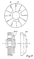
- Figure 18 illustrates the rotational shaft with the hysteresis-dampened magnetic coupling, the air bearing and the flywheel 52, the polygon being secured to said flywheel.
- the portion of the rotational shaft disposed in the air bearing comprises a cylinder 53 of a relatively heavy material, such as granite.
- the flywheel 52 is placed to the right of the granite cylinder 53, the polygonal mirror 32 being secured to said flywheel in an adjustable manner.
- a relatively strong magnet 54 is placed at the end of the shaft, said magnet 54 being repelled in axial direction by a second fixed magnet 55.
- the axial position of the rotational shaft is maintained by means of the pressure inside the air bearing and in particular by the pressure causing a pressing of the shaft in axial direction against the force of the magnets 54, 55.
- the shaft is caused to rotate by a stepmotor 51 disposed to the left of the magnetic coupling.
Landscapes
- Physics & Mathematics (AREA)
- Optics & Photonics (AREA)
- Engineering & Computer Science (AREA)
- Plasma & Fusion (AREA)
- Mechanical Engineering (AREA)
- General Physics & Mathematics (AREA)
- Manufacture Or Reproduction Of Printing Formes (AREA)
- Facsimile Scanning Arrangements (AREA)
- Piezo-Electric Or Mechanical Vibrators, Or Delay Or Filter Circuits (AREA)
- Exposure And Positioning Against Photoresist Photosensitive Materials (AREA)
- Laser Beam Printer (AREA)
- Photosensitive Polymer And Photoresist Processing (AREA)
- Mechanical Optical Scanning Systems (AREA)
- Magnetic Bearings And Hydrostatic Bearings (AREA)
Applications Claiming Priority (2)
| Application Number | Priority Date | Filing Date | Title |
|---|---|---|---|
| DK510389A DK162469C (da) | 1989-10-13 | 1989-10-13 | Fremgangsmaade til fremstilling af trykplader ved hjaelp af en laserstraale |
| DK5103/89 | 1989-10-13 |
Publications (3)
| Publication Number | Publication Date |
|---|---|
| EP0423054A2 true EP0423054A2 (de) | 1991-04-17 |
| EP0423054A3 EP0423054A3 (en) | 1992-01-22 |
| EP0423054B1 EP0423054B1 (de) | 1994-12-28 |
Family
ID=8139472
Family Applications (1)
| Application Number | Title | Priority Date | Filing Date |
|---|---|---|---|
| EP90610066A Expired - Lifetime EP0423054B1 (de) | 1989-10-13 | 1990-10-11 | Verfahren zur Herstellung von Druckplatten mit Hilfe eines Laserstrahls |
Country Status (6)
| Country | Link |
|---|---|
| EP (1) | EP0423054B1 (de) |
| JP (1) | JPH03171052A (de) |
| AT (1) | ATE116180T1 (de) |
| DE (1) | DE69015554T2 (de) |
| DK (1) | DK162469C (de) |
| IL (1) | IL95960A0 (de) |
Cited By (2)
| Publication number | Priority date | Publication date | Assignee | Title |
|---|---|---|---|---|
| DE4225946A1 (de) * | 1992-08-06 | 1994-02-10 | Krause Biagosch Gmbh | Vorrichtung zur Laser-Belichtung eines Druckformträgers |
| EP0917003A1 (de) * | 1996-09-11 | 1999-05-19 | KOREA INSTITUTE OF MACHINERY & MATERIALS | Methode zur Herstellung von Siebschablonen und Apparat zur Ausführung dieser Methode |
Families Citing this family (2)
| Publication number | Priority date | Publication date | Assignee | Title |
|---|---|---|---|---|
| DK207090D0 (da) * | 1990-08-29 | 1990-08-29 | Andersen Allan V | Fremgangsmaade og apparat til udfoerelse af tromlescanning |
| SE502083C2 (sv) * | 1991-05-28 | 1995-08-07 | Misomex Ab | Förfarande och anordning för automatiserad exponering av ljuskänsligt material medelst laserljus |
-
1989
- 1989-10-13 DK DK510389A patent/DK162469C/da not_active IP Right Cessation
-
1990
- 1990-10-10 IL IL95960A patent/IL95960A0/xx unknown
- 1990-10-11 DE DE69015554T patent/DE69015554T2/de not_active Expired - Fee Related
- 1990-10-11 AT AT90610066T patent/ATE116180T1/de active
- 1990-10-11 EP EP90610066A patent/EP0423054B1/de not_active Expired - Lifetime
- 1990-10-12 JP JP2272504A patent/JPH03171052A/ja active Pending
Cited By (2)
| Publication number | Priority date | Publication date | Assignee | Title |
|---|---|---|---|---|
| DE4225946A1 (de) * | 1992-08-06 | 1994-02-10 | Krause Biagosch Gmbh | Vorrichtung zur Laser-Belichtung eines Druckformträgers |
| EP0917003A1 (de) * | 1996-09-11 | 1999-05-19 | KOREA INSTITUTE OF MACHINERY & MATERIALS | Methode zur Herstellung von Siebschablonen und Apparat zur Ausführung dieser Methode |
Also Published As
| Publication number | Publication date |
|---|---|
| EP0423054B1 (de) | 1994-12-28 |
| ATE116180T1 (de) | 1995-01-15 |
| DK510389D0 (da) | 1989-10-13 |
| DK162469B (da) | 1991-10-28 |
| DK162469C (da) | 1992-03-23 |
| DE69015554T2 (de) | 1995-08-10 |
| IL95960A0 (en) | 1991-07-18 |
| DE69015554D1 (de) | 1995-02-09 |
| JPH03171052A (ja) | 1991-07-24 |
| EP0423054A3 (en) | 1992-01-22 |
| DK510389A (da) | 1991-04-14 |
Similar Documents
| Publication | Publication Date | Title |
|---|---|---|
| US5185676A (en) | Beam scanning apparatus and apparatus for writing image information | |
| US4810941A (en) | Control system for a servomotor | |
| EP0295863B1 (de) | Optischer Drucker vom Abtastungs-Typ | |
| JPS619077A (ja) | 巻取紙の同期方法および同期装置 | |
| US6243123B1 (en) | Light beam scanning apparatus for use with image forming apparatus | |
| EP1246712B1 (de) | Laserstrahlvorrichtung zum zielen und verfahren zum schneiden oder markieren eines werkstücks | |
| US4725855A (en) | Multi-beam laser printer with beam spacing detection during blanking time | |
| EP0423054B1 (de) | Verfahren zur Herstellung von Druckplatten mit Hilfe eines Laserstrahls | |
| US5107280A (en) | Divisional exposure apparatus | |
| EP0869384A1 (de) | Winkeldetektor und detektionsverfahren mit spiegel | |
| JPH116970A (ja) | 画像作成装置用の多ビーム走査システム | |
| EP0420198B1 (de) | Strahlabtastvorrichtung und Bildinformationsschreibvorrichtung | |
| JP3132690B2 (ja) | 光空間伝送装置 | |
| JPH11156567A (ja) | レーザ印字装置 | |
| JPH01147516A (ja) | ビーム位置制御装置 | |
| JP3850308B2 (ja) | ガルバノスキャナのデジタル制御方法及び装置 | |
| JP2006224142A (ja) | レーザ走査装置およびレーザマーキング装置、ならびにレーザマーキング方法 | |
| JPH0481808A (ja) | 光線走査装置 | |
| JPH0480708A (ja) | 光線走査装置 | |
| GB2293460A (en) | Scanning optical system | |
| JPH02121789A (ja) | 光走査レーザー加工装置 | |
| JP2001027737A (ja) | 光走査装置 | |
| JPH0480709A (ja) | 光線走査装置 | |
| JP2000338442A (ja) | 光偏向走査装置 | |
| JPH10325929A (ja) | 走査光学装置 |
Legal Events
| Date | Code | Title | Description |
|---|---|---|---|
| PUAI | Public reference made under article 153(3) epc to a published international application that has entered the european phase |
Free format text: ORIGINAL CODE: 0009012 |
|
| AK | Designated contracting states |
Kind code of ref document: A2 Designated state(s): AT BE CH DE ES FR GB GR IT LI LU NL SE |
|
| 17P | Request for examination filed |
Effective date: 19910921 |
|
| RAP1 | Party data changed (applicant data changed or rights of an application transferred) |
Owner name: KRAUSE-BIAGOSCH GMBH |
|
| PUAL | Search report despatched |
Free format text: ORIGINAL CODE: 0009013 |
|
| AK | Designated contracting states |
Kind code of ref document: A3 Designated state(s): AT BE CH DE ES FR GB GR IT LI LU NL SE |
|
| 17Q | First examination report despatched |
Effective date: 19930420 |
|
| GRAA | (expected) grant |
Free format text: ORIGINAL CODE: 0009210 |
|
| AK | Designated contracting states |
Kind code of ref document: B1 Designated state(s): AT BE CH DE ES FR GB GR IT LI LU NL SE |
|
| PG25 | Lapsed in a contracting state [announced via postgrant information from national office to epo] |
Ref country code: BE Effective date: 19941228 Ref country code: IT Free format text: LAPSE BECAUSE OF FAILURE TO SUBMIT A TRANSLATION OF THE DESCRIPTION OR TO PAY THE FEE WITHIN THE PRE;WARNING: LAPSES OF ITALIAN PATENTS WITH EFFECTIVE DATE BEFORE 2007 MAY HAVE OCCURRED AT ANY TIME BEFORE 2007. THE CORRECT EFFECTIVE DATE MAY BE DIFFERENT FROM THE ONE RECORDED.SCRIBED TIME-LIMIT Effective date: 19941228 Ref country code: GR Free format text: LAPSE BECAUSE OF FAILURE TO SUBMIT A TRANSLATION OF THE DESCRIPTION OR TO PAY THE FEE WITHIN THE PRESCRIBED TIME-LIMIT Effective date: 19941228 Ref country code: AT Effective date: 19941228 Ref country code: FR Effective date: 19941228 Ref country code: LI Effective date: 19941228 Ref country code: NL Effective date: 19941228 Ref country code: ES Free format text: THE PATENT HAS BEEN ANNULLED BY A DECISION OF A NATIONAL AUTHORITY Effective date: 19941228 Ref country code: CH Effective date: 19941228 |
|
| REF | Corresponds to: |
Ref document number: 116180 Country of ref document: AT Date of ref document: 19950115 Kind code of ref document: T |
|
| REF | Corresponds to: |
Ref document number: 69015554 Country of ref document: DE Date of ref document: 19950209 |
|
| PG25 | Lapsed in a contracting state [announced via postgrant information from national office to epo] |
Ref country code: SE Effective date: 19950328 |
|
| REG | Reference to a national code |
Ref country code: CH Ref legal event code: PL |
|
| EN | Fr: translation not filed | ||
| NLV1 | Nl: lapsed or annulled due to failure to fulfill the requirements of art. 29p and 29m of the patents act | ||
| PG25 | Lapsed in a contracting state [announced via postgrant information from national office to epo] |
Ref country code: GB Effective date: 19951011 |
|
| PGFP | Annual fee paid to national office [announced via postgrant information from national office to epo] |
Ref country code: DE Payment date: 19951027 Year of fee payment: 6 |
|
| PG25 | Lapsed in a contracting state [announced via postgrant information from national office to epo] |
Ref country code: LU Free format text: LAPSE BECAUSE OF NON-PAYMENT OF DUE FEES Effective date: 19951031 |
|
| PLBE | No opposition filed within time limit |
Free format text: ORIGINAL CODE: 0009261 |
|
| STAA | Information on the status of an ep patent application or granted ep patent |
Free format text: STATUS: NO OPPOSITION FILED WITHIN TIME LIMIT |
|
| 26N | No opposition filed | ||
| GBPC | Gb: european patent ceased through non-payment of renewal fee |
Effective date: 19951011 |
|
| PG25 | Lapsed in a contracting state [announced via postgrant information from national office to epo] |
Ref country code: DE Effective date: 19970701 |