EP0423103A2 - Porte d'ascenseur rétractable - Google Patents
Porte d'ascenseur rétractable Download PDFInfo
- Publication number
- EP0423103A2 EP0423103A2 EP90870180A EP90870180A EP0423103A2 EP 0423103 A2 EP0423103 A2 EP 0423103A2 EP 90870180 A EP90870180 A EP 90870180A EP 90870180 A EP90870180 A EP 90870180A EP 0423103 A2 EP0423103 A2 EP 0423103A2
- Authority
- EP
- European Patent Office
- Prior art keywords
- door
- hinge pin
- track
- cab
- panel
- Prior art date
- Legal status (The legal status is an assumption and is not a legal conclusion. Google has not performed a legal analysis and makes no representation as to the accuracy of the status listed.)
- Withdrawn
Links
- 230000000712 assembly Effects 0.000 claims abstract description 15
- 238000000429 assembly Methods 0.000 claims abstract description 15
- 230000000295 complement effect Effects 0.000 claims abstract description 5
- 229920003023 plastic Polymers 0.000 description 7
- 239000004033 plastic Substances 0.000 description 6
- 239000007787 solid Substances 0.000 description 5
- 230000008901 benefit Effects 0.000 description 3
- 239000002023 wood Substances 0.000 description 2
- BTFMCMVEUCGQDX-UHFFFAOYSA-N 1-[10-[3-[4-(2-hydroxyethyl)-1-piperidinyl]propyl]-2-phenothiazinyl]ethanone Chemical compound C12=CC(C(=O)C)=CC=C2SC2=CC=CC=C2N1CCCN1CCC(CCO)CC1 BTFMCMVEUCGQDX-UHFFFAOYSA-N 0.000 description 1
- 239000004677 Nylon Substances 0.000 description 1
- 230000005540 biological transmission Effects 0.000 description 1
- 239000000463 material Substances 0.000 description 1
- 230000004048 modification Effects 0.000 description 1
- 238000012986 modification Methods 0.000 description 1
- 229920001778 nylon Polymers 0.000 description 1
- 229960004265 piperacetazine Drugs 0.000 description 1
- 230000000717 retained effect Effects 0.000 description 1
Images


Classifications
-
- B—PERFORMING OPERATIONS; TRANSPORTING
- B66—HOISTING; LIFTING; HAULING
- B66B—ELEVATORS; ESCALATORS OR MOVING WALKWAYS
- B66B13/00—Doors, gates, or other apparatus controlling access to, or exit from, cages or lift well landings
- B66B13/30—Constructional features of doors or gates
- B66B13/303—Details of door panels
- B66B13/305—Slat doors for elevators
Definitions
- the present invention relates to the field of elevators, and especially to manually operated doors for small elevators.
- doors for opening and closing the entrance and exit opening through which passengers enter and exit the elevator are generally comprised of two sets of large solid door panels that are moved from the open to the closed position and back, on colinear tracks, by one electric motor.
- One set of door panels is for the elevator cab, and the other set of door panels is for the hoistway. The door panels are moved toward each other to close the opening. and away from each other to open the opening.
- the door panels When the large solid door panels are moved away from each other to open the opening, the door panels are often moved into receiving areas, outside the elevator cab, that are large enough to accommodate the panels. Since the door panels are relatively large, the receiving areas outside the elevator cab for the door panels must also be relatively large. In large commercial buildings, there may be no problem in providing the space needed outside the elevator cab for receiving the door panels. Also, in a large commercial building there may be no problem in providing the additional space needed outside the elevator cab for housing an electric motor and accompanying power transmission devices such as cables and pulleys.
- an elevator when used in a relatively small structure, such as in a private home or small apartment building, it may not be possible to provide enough space outside the elevator cab for receiving relatively large elevator door panels when the cab opening is open; and it may not be possible to provide enough space outside the elevator cab for housing an electric motor and associated cables and pulleys for opening and closing the door panels.
- a private home or small apartment building may simply not have enough space outside the elevator cab to alot for relatively large elevator door panels. It would be desirable, therefore, to provide an elevator door that does not require alot of space outside the elevator cab for receipt of door panels when the cab and hoistway opening is open.
- U.S. Patent 2,025,566 of Bogart discloses an elevator gate that takes a 90 degree turn on vertically oriented rollers and a track inside an elevator cab.
- U.S. Patent 2,100,882 of Tamsitt discloses an elevator gate taking a 90 degree turn on vertically oriented rollers and a track inside the elevator cab.
- the elevator gate moves away from the 90 degree bend and becomes, in essence, the hypotenuse of a right triangle with the other sides of the triangle being defined by the front and side portions of the track adjacent the 90 degree bend.
- the elevator gate undesirably takes up precious elevator cab space. It would be desirable, therefore, if the gate for the interior of an elevator be movable from the open to the closed position without taking up much of the interior cab space in doing so.
- Some small elevators used in private homes or small apartment buildings employ manually operated, collapsible type gates.
- One disadvantage with such gates is that they have many open areas between the solid elements forming the gate. The open areas may pose a problem in that they permit an elevator passenger to accidentally put a limb, such as a finger, hand, or foot, through an opening and expose that limb to possible extreme danger. If a limb protrudes through such an opening when the elevator is in operation, the limb can be crushed between the moving elevator cab and the stationary hoistway wall adjacent to the elevator cab. If would be desirable, therefore, if a manually operated elevator door were provided that would avoid the use of open spaces in the door and would prevent a limb from being caught between a moving elevator cab and stationary building structures.
- solid elevator doors are comprised of opaque materials. As such, when a passenger is in the elevator cab and the door is closed, the passenger is unable to see outside the cab. Conversely, when the elevator door is closed, no one outside the elevator cab can look inside the cab. For a number of reasons, it would be desirable for the door of an elevator to have at least some transparent portions to permit passengers in the cab to see outside the cab and to permit persons outside the cab to see into the cab. For example, security of passengers would be greatly enhanced if persons outside the cab could see inside while the doors were closed.
- Another object of the invention is to provide an elevator door that, in the open position, allows the greatest possible open space to walk through in relation to cab width.
- Still another object of the invention is to provide a door for the interior of an elevator that is movable from the open to the closed position without taking up much of the interior cab space in doing so.
- Another object of the invention is to provide an elevator door that does not have large open spaces in the door thereby preventing a limb of an elevator passenger from being caught between a moving elevator cab and stationary building structures.
- a retractable elevator door is provided.
- the elevator door especially an elevator cab door, includes a plurality of relatively narrow door panels that are connected to and that are supported by, hinge structures located between the sides of adjacent door panels.
- the hinge structures of the invention are supported from above by a carriage which rides in a top track which includes a 90 degree bend.
- the track supporting the door has a front portion, the 90 degree bend, and a side portion.
- the plurality of relatively narrow door panels are hanging from the carriages located in the front portion of the track.
- the plurality of door panels are moved through the 90 degree bend and are moved to the side portion of the track.
- the plurality of door panels are located in the side portion of the track.
- the door panels are supported by a plurality of door panel support assemblies which are characterized in including a carriage for top rollers which move in the top track, a hinge pin supported by the carriage and extending down from the carriage and supporting adjacent door panels, and a bottom guide roller which moves in a bottom track.
- a door panel support assembly and an associated door panel may be thought of, in combination, as a door panel assembly.
- the track for the door panels may be located entirely within the interior of the elevator cab. With the track being located within the elevator cab, the retractable door of the invention does not require space outside the cab to house the cab door.
- the retractable elevator door of the invention includes a plurality of door panels, in contrast with a single solid elevator door as disclosed in the prior art, the amount of space that the door panels of the invention occupy in the interior of the elevator cab, when they move through the 90 degree bend, is substantially reduced to the point of being negligible.
- an elevator door is provided that does not require alot of space outside the elevator cab for receipt of door panels when the cab opening is open.
- an elevator cab door is provided that does not require an electric motor and associated cables and pulleys for opening and closing the cab opening.
- the invention provides a gate for the interior of an elevator that is movable from the open to the closed position without taking up much of the interior cabin space in doing so, and allows for the maximum clear open area in relation to cab width.
- the invention provides an elevator door that avoids the use of open spaces in a closed door and prevents a passenger's limb from being caught between a moving elevator cab and stationary building structures.
- elevator doors are provided in which at least a transparent door portion permits passengers inside the elevator cab to see outside the cab and permits persons outside the cab to see inside the cab when the door is closed.
- a combination which includes a retractable door assembly having a closed position covering the access opening and further having a retracted position substantially adjacent to the side wall of the elevator cab.
- the door assembly is segmented and includes a plurality of panels pivoted with respect to each other by hinge pins.
- a trackway for supporting the door assembly includes upper and lower guide tracks, respectively.
- Each guide track includes a curved portion substantially between the access opening and the side wall portion of the elevator cab.
- a carriage is connected to each door panel for supporting the weight thereof.
- Each carriage includes at least one first guide roller (preferably a set of wheels) journaled substantially on a horizontal axis and riding in the upper guide track.
- Each carriage further includes a second guide roller journaled substantially on a vertical axis (hinge pin) and riding in the lower guide track.
- the first guide roller has a lateral clearance with respect to at least the curved portion of the guide track, so that any lateral thrust loads are taken up by the second guide roller (a tangential roller) as the segmented door is retracted into its open position and extended into its closed position with respect to the elevator cab, respectively.
- the tangential roller in guiding the door panels, prevents the carriage wheels from rubbing up against side walls adjacent the guide tracks. Thereby, carriage wheels roll freely as the door panels move through the respective right angle bends.
- an elevator cab 10 is shown suspended by cables 12 within a hoistway 14 having walls 16.
- the cab includes cab walls 18, ceiling 20, and floor 22.
- a retractable elevator cab door 11 wherein the door 11 is in the open (or retracted) position (also see Fig. 3).
- the door 11 is segmented and includes a plurality of door panels 24 pivoted with respect to one another.
- the door panels 24 are supported by upper horizontal support bars 26 and lower horizontal support bars 28.
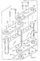
- the support bars 26 and 28 have mid-portions 27 and 29, respectively, which are directly attached to the panels 24 such as by screws 30 (shown in Fig. 7).
- the horizontal support bars 26 and 28 have end portions which include orifices 31 and 33, respectively, (shown in Fig. 7).
- adjacent horizontal support bars 26 and 26a of adjacent door panels 24 and 24a, respectively overlap one another when their orifices 31 and 31a are about to be placed in pivotal connection with hinge pin 51.
- a top track 36 supported by the cab ceiling 20, includes a front portion 38 which is substantially parallel to cab opening 40 (or access opening) and is adjacent thereto.
- a curved track portion 42 is contiguous with the front portion 38 and undergoes a substantially right angle (90 degrees) bend.
- a side track portion 44 is contiguous to the right angle bend portion 42 and is substantially parallel to a side wall 18 of the cab 10 and is adjacent thereto.
- the front and side track portions may be fabricated from wood or plastic.
- the curved track portion 42 is preferably fabricated from plastic.
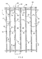
- the door 11 of the invention includes a plurality of door panel assemblies 46 (one of which is shown in the dashed box shown in Fig. 2).
- the door panel assemblies 46 (or more simply, door assemblies) are supported by and guided by the top track 36 and are capable of being moved along the track 36, whereby they serve to open the cab opening 40 when they are located in the side track portion 44 away from the cab opening 40 as shown in Fig. 3; and whereby they close the cab opening 40 when they are located parallel to the cab opening 40 in front track portion 38.
- line 45 represents a line drawn along side the outer edge of the door panels 24 in the open (or retracted) position and is parallel to the side track portion 44 which is parallel to the side wall 18.
- the door panels 24 are bounded by line 45.
- Line 45 extends to intersect another line 47 at a right angle.
- Line 47 represents a line drawn parallel to the front wall track portion 38 which is parallel to cab opening 40 and would be along side the outer edge of door panels 24 when the door is in the closed position.
- door panels 24 would be bounded by line 47.
- An important feature of the present invention is that as the door is moved from the open to the closed position, and vice versa, the door panels 24 do not cross over the bounding lines 45 and 47.
- This feature provides the additional benefit of permitting the track 36 and panels 24 to be located close to the interior cab wall 18 without having the panels 24 hit the wall 18 as they move through the right angle bend portion 42. Furthermore, by placing the door very near the interior cab wall 16, but not rubbing the wall 16, more space is available for passengers inside the elevator.
- each of a plurality of the door assemblies 46 includes a carriage 48 which is supported by the top track 36 and is guided thereby.
- a straight hinge pin 50 is supported by the carriage 48 and extends down toward the bottom or floor 22 of the elevator cab 10. Movement of the hinge pin 50 when the door 11 is opened or closed is guided by the top track 36.
- the hinge pin 50 includes a top end 54 and a bottom end 56.
- the horizontal support bar 28 (in Fig. 4) is located at the bottom end of the panel 24 near the bottom end 56 of the hinge pin 50.
- a lock nut 58 (in Fig. 4) is located near the bottom end 56 of the hinge pin 50 and supported thereby.
- the lock nut 58 may be supported by the hinge pin 50 by means of screw threads.
- the lock nut 58 supports the weight of adjacent door panels 24 by supporting the bottommost panel supports 28 of adjacent panels.
- a tangential roller 60 is supported by and journaled on the hinge pin 50 and is located near the top end of the hinge pin 50.
- the tangential roller 60 rotates on the hinge pin 50.
- Vertical axis 52 serves as the axis of rotation for the tangential roller 60.
- the tangential roller 60 serves as a second guide roller assembly in conjunction with a first guide roller assembly comprised of wheels 70, 71 and 72 described below.
- Tangential roller 60 engages a lower complementary guide portion 62 in the curved portion 42 of top track 36 (see also Fig. 8A) whereby movement of the door assemblies 46 through the curved track portion 42 is facilitated.
- the top track 36 is comprised of a trackway that includes inner and outer parallel track portions 62 and 64, respectively, in the front and side track portions.
- the tracks include inner and outer concentric track portions 66 and 68, respectively (shown also in Fig. 8A) in the curved portion 42.
- the curved portion 42 may be composed of a one-piece plastic fixture 42 which includes both the inner and outer concentric track portions 66 and 68.
- Top plate 67 keeps the track portions 66 and 68 in stable arrangement with respect to one another.
- a slot 69 for travel of the hinge pins 50 is also shown.
- the carriage 48 includes three wheels journaled substantially or horizontal axes and arranged in a triangular pattern.
- Two wheels 70 and 71 are arranged in tandem and are located at two vertices 73 and 74 of the triangle 75.
- a single wheel 72 is located at the third vertex 76 of the triangle 75.
- the wheels 70, 71 and 72 comprise a first guide roller assembly.
- the two tandem carriage wheels 70 and 71 are positioned to ride in the outer tracks 64 and 68, and the single carriage wheel 72 is positioned in the inner tracks 62 and 66, whereby the carriage 48 is capable of readily move through the curved track portion 42 which has a tight radius for a right angle bend.
- the tracks 64, 68, 62 and 66 form upper quide tracks of a trackway.
- the hinge pin 50 and vertical axis 52 are located at the center of the triangle 75.
- a combination which includes a retractable door assembly having a closed position covering the access opening and further having a retracted position substantially adjacent to the side wall of the elevator cab.
- the door assembly is segmented and includes a plurality of panels 24 pivoted with respect to each other by hinge pins 50.
- a trackway for supporting the door assembly includes upper and lower guide tracks, respectively.
- Upper guide track is comprised of tracks 64, 68, 62 and 66.
- Lower guide track is comprised of guide portion 63.
- Each guide track includes a curved portion substantially between the access opening and the side wall portion of the elevator cab.
- a carriage 48 is connected to each door panel 24 for supporting the weight thereof.
- Each carriage 48 includes at least one first guide roller (wheels 70, 71, 72) journaled substantially on a horizontal axis and riding in the upper guide track.
- Each carriage further includes a second guide roller (tangential roller 60) journaled substantially on a vertical axis (hinge pin 50) and riding in the lower guide track.
- the first guide roller has a lateral clearance with respect to at least the curved portion of the guide track, so that any lateral thrust loads are taken up by the second guide roller (tangential roller 60) as the segmented door is retracted into its open position and extended into its closed position with respect to the elevator cab, respectively. Thereby a free and easy movement is assured and jamming problems are eliminated as the segmented door is guided by the lower guide track.
- the tangential roller 60 in guiding the door panels 24, prevents the carriage wheels 70, 71 and 72 from rubbing up against the side walls adjacent the tracks 66 and 68. Thereby, wheels 70, 71 and 72 roll freely as the door panels 24 move through the respective right angle bends.
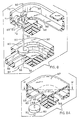
- Fig. 8 shows how the center of the carriage 48, the hinge pin 50, the tangential rollers 60 and 90, and the bottom roller 88 turn simultaneously on the vertical axis 52.
- a hinge pin slot 69 the inner track portion 66, and the outer concentric track portion 68 of the right angle track portion 42 are shown.
- the outer track portion 68 takes the form of an enlarged, non-circular band.
- a circular band is shown as bordered by dashed line 83.
- the surface area 87 in the region between dashed line 83 and side wall 85 of the one-piece plastic fixture 42 is provided to accommodate the outer wheels 70 and 71 of the carriage 48 shown in Fig. 5. If the surface area 87 were not provided, the outer wheels 70 and 71 would bind up against a concentric outer wall of the fixture 42.
- nylon bushings 78 are provided to space upper and lower hollow tubes 80 and 81, respectively, from the hinge pin 50.
- the bushings 78 may be forced into the hollow tube 80 to be supported thereby.
- the hollow tubes 80 and 81 by being spaced from the hinge pin 50, serve to jacket the hinge pin 50 and serves to occupy most of the space between the hinge pin 50 and edges of adjacent panels 24. With the tubes 80 and 81 occupying the space between adjacent panels 24 and the hinge pin 50, the tubes 80 and 81 prevent limbs, such as fingers, hands, and arms, of elevator passengers from entering. the space between the hinge pin 50 and adjacent panels 24.
- Right angle brackets 82 are attached to door panels 24 and retain the hollow tubes 80 and 81 jacketing the hinge pin 50.
- a sheet may be attached to the door panel 24 and may extend around the hinge pin 50 in order to occupy space between the hinge pin 50 and an edge of an adjacent panel 24, whereby the sheet prevents limbs of elevator passengers from entering the space between the hinge pin 50 and an adjacent panel 24.
- a bottom track 86 is also present. Both the top track 36 and the bottom track 86 are supported by the cab 10, and both tracks have front portions, curved portions, and side portions.
- the straight hinge pin 50 supported by the carriage 48, extends down to the bottom track 86. Movement of the hinge pin 50 is guided by both the top and bottom tracks.
- a bottom roller 88 is connected to the bottom end of the hinge pin 50.
- the bottom roller 88 rides in the bottom horizontal track 86.
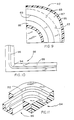
- a second tangential roller 90 is located near the bottom end of the hinge pin 50. Tangential roller 90 rides in a complementary bottom roller guide portion 92 (see Fig. 11) of the bottom circular portion 94 of the bottom track 86.
- Bottom track 86 includes front portion 96, circular portion 94, and side portion 98. Front and side portions 96 and 98, respectively, may be fabricated from wood or plastic. Preferably, circular portion 94 is fabricated from plastic.
- Fig. 12 shows a door panel 24 that includes transparent plastic windows 100.
- the windows 100 permit a passenger to see out the cab 10 and permit a person outside the elevator to see inside the cab 10.
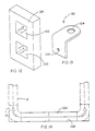
- Fig. 13 shows a right angle bracket 82 that is used to pivotally connect a door panel 24 with a hinge pin 50 at a point mid-way down the hinge pin 50. More specifically, a fastener, such as a screw (not shown) can be inserted through small side hole 102 to secure the right angle bracket 82 to the side of a door panel.
- the hinge pin hole 104 is horizontally oriented to receive a hinge pin 50 to pivotally connect the door panel 24 to the hinge pin 50.
- right angle brackets for adjacent door panels are installed on the adjacent door panels so that the hinge pin holes 104 of adjacent angle brackets 82 overlap one another, permitting a hinge pin 50 to pivotally connect both door panels to the same hinge pin.
- Fig. 14 shows another embodiment of the retractable elevator door of the invention.
- the inner door 106 is the cab door.
- the outer door 108 is the hoistway door.
- a clutch (not shown) on the cab door 106 engages a roller (not shown) on the hoistway door 108.
- the hoistway door 108 is engaged and is operated simultaneously with the cab door 106.
- the cab door 106 is retracted to an open position, whereby the door panels are located outside the cab wall 18 in the space between the outside of the cab walls 18 and the hoistway wall 16.
- the upper and lower side track portions can be located either inside the cab or outside the cab between the cab wall and the hoistway wall. Accordingly, it will be appreciated by those skilled in the art that within the scope of the appended claims, the invention may be practiced other than has been specifically described herein.
Landscapes
- Elevator Door Apparatuses (AREA)
Applications Claiming Priority (2)
| Application Number | Priority Date | Filing Date | Title |
|---|---|---|---|
| US07/420,536 US5036953A (en) | 1989-10-12 | 1989-10-12 | Retractable elevator door |
| US420536 | 1989-10-12 |
Publications (2)
| Publication Number | Publication Date |
|---|---|
| EP0423103A2 true EP0423103A2 (fr) | 1991-04-17 |
| EP0423103A3 EP0423103A3 (en) | 1991-10-23 |
Family
ID=23666868
Family Applications (1)
| Application Number | Title | Priority Date | Filing Date |
|---|---|---|---|
| EP19900870180 Withdrawn EP0423103A3 (en) | 1989-10-12 | 1990-10-10 | Retractable elevator door |
Country Status (2)
| Country | Link |
|---|---|
| US (1) | US5036953A (fr) |
| EP (1) | EP0423103A3 (fr) |
Cited By (4)
| Publication number | Priority date | Publication date | Assignee | Title |
|---|---|---|---|---|
| EP0829448A1 (fr) * | 1996-09-13 | 1998-03-18 | Inventio Ag | Porte coulissante |
| US7424935B1 (en) | 2005-12-07 | 2008-09-16 | Columbia Elevator Solutions, Inc. | Elevator door assembly |
| FR2913713A1 (fr) * | 2007-03-13 | 2008-09-19 | Bubendorff Sa | Dispositif mobile, de type porte sectionnelle a ouverture laterale ou verticale |
| EP2003082A1 (fr) * | 2007-06-18 | 2008-12-17 | Motala Hissar AB | Porte motorisée pour cabines d'ascenseur |
Families Citing this family (12)
| Publication number | Priority date | Publication date | Assignee | Title |
|---|---|---|---|---|
| DE59107332D1 (de) * | 1990-07-24 | 1996-03-14 | Karlheinz Bockisch | Falttor |
| US5549148A (en) * | 1994-06-01 | 1996-08-27 | Wrono Enterprise Corp. | Blade for accordion storm shutter |
| US5477903A (en) * | 1994-06-01 | 1995-12-26 | Wrono Enterprise Corporation | Accordion storm shutter |
| US5927367A (en) * | 1997-03-19 | 1999-07-27 | Toti; Andrew J. | Track system, including stabilized, offset-wheel carriers |
| US6082499A (en) * | 1998-08-05 | 2000-07-04 | Vertisys International, Inc. | Wrap-around elevator door |
| US6745813B2 (en) * | 2000-07-31 | 2004-06-08 | Kim Charles Yorgason | Rolling pivot for track suspended articulated panels |
| JP5441186B2 (ja) * | 2011-06-07 | 2014-03-12 | アイシン精機株式会社 | シートスライド装置 |
| US9212027B1 (en) * | 2011-09-28 | 2015-12-15 | A+ Elevators & Lifts LLC | Gate system for residential elevators |
| EP3246283B1 (fr) * | 2016-05-17 | 2019-09-18 | KONE Corporation | Panneau de porte d'ascenseur |
| CN109319644B (zh) * | 2018-10-12 | 2023-09-05 | 佛山市高明区安承升降装备研究院 | 一种具有防台风功能的电梯层门 |
| GB2586142B (en) * | 2019-08-07 | 2023-04-12 | Safran Seats Gb Ltd | Aircraft seat and cam followers |
| CN111186757A (zh) * | 2020-01-22 | 2020-05-22 | 杭州宝宸科技有限公司 | 一种新型电梯门结构系统 |
Family Cites Families (9)
| Publication number | Priority date | Publication date | Assignee | Title |
|---|---|---|---|---|
| US1180156A (en) * | 1914-01-08 | 1916-04-18 | John V Kranebiel | Elevator. |
| US1654857A (en) * | 1925-07-01 | 1928-01-03 | Otis Elevator Co | Gate |
| US1735153A (en) * | 1927-06-10 | 1929-11-12 | Westinghouse Electric & Mfg Co | Door-operating device for elevators |
| US2689003A (en) * | 1950-03-07 | 1954-09-14 | Helbert Francis | Sliding door |
| FR1183386A (fr) * | 1957-09-26 | 1959-07-07 | Porte coulissante à ferrage par aiguilles pour garages ou autres locaux | |
| US3003551A (en) * | 1959-05-28 | 1961-10-10 | Starline | Track suspended multiple panel door |
| FR1443584A (fr) * | 1965-07-16 | 1966-06-24 | L Garnier Ets | Dispositif de guidage et de jonction amovible des lames agrafées pour portes de fermeture à déplacement horizontal |
| FR1587151A (fr) * | 1968-10-18 | 1970-03-13 | ||
| FR2513956A1 (fr) * | 1981-10-01 | 1983-04-08 | Deprat Ets Jean | Chariot simple galet avec guide |
-
1989
- 1989-10-12 US US07/420,536 patent/US5036953A/en not_active Expired - Fee Related
-
1990
- 1990-10-10 EP EP19900870180 patent/EP0423103A3/en not_active Withdrawn
Cited By (4)
| Publication number | Priority date | Publication date | Assignee | Title |
|---|---|---|---|---|
| EP0829448A1 (fr) * | 1996-09-13 | 1998-03-18 | Inventio Ag | Porte coulissante |
| US7424935B1 (en) | 2005-12-07 | 2008-09-16 | Columbia Elevator Solutions, Inc. | Elevator door assembly |
| FR2913713A1 (fr) * | 2007-03-13 | 2008-09-19 | Bubendorff Sa | Dispositif mobile, de type porte sectionnelle a ouverture laterale ou verticale |
| EP2003082A1 (fr) * | 2007-06-18 | 2008-12-17 | Motala Hissar AB | Porte motorisée pour cabines d'ascenseur |
Also Published As
| Publication number | Publication date |
|---|---|
| EP0423103A3 (en) | 1991-10-23 |
| US5036953A (en) | 1991-08-06 |
Similar Documents
| Publication | Publication Date | Title |
|---|---|---|
| US5036953A (en) | Retractable elevator door | |
| US4557073A (en) | Revolving doors | |
| US3103967A (en) | Screen door assembly for garages | |
| US3618656A (en) | Folding door apparatus | |
| EP0065398A1 (fr) | Constructions comprenant de parois coulissantes dans leur plan | |
| JPS6245154B2 (fr) | ||
| AU755125B2 (en) | Revolving door with a night closing panel | |
| US20180266174A1 (en) | Door for personnel ingress and egress provided within a larger door for vehicles | |
| CA2073212C (fr) | Systemes d'ascenseurs pour immeuble | |
| US5425409A (en) | Door mounting system | |
| US3796015A (en) | Car pod | |
| US6493991B1 (en) | Revolving door system | |
| JP2992614B2 (ja) | 自動回転スライドドア装置 | |
| JP2557576Y2 (ja) | 超重量扉の開閉構造 | |
| EP0507993B1 (fr) | Dispositif d'ouverture et de fermeture d'une pluralité de vantaux à mouvement tournant et coulissant | |
| KR200385183Y1 (ko) | 슬라이딩 타입 게이트 장치 | |
| JPH01101918A (ja) | 天井収納装置 | |
| US3028639A (en) | Aircraft hanger doors | |
| JPH0743107Y2 (ja) | エレベータの円形ドア駆動装置 | |
| JPH07166773A (ja) | 航空機格納庫の開閉扉 | |
| KR960001501Y1 (ko) | 지하용 다층 순환식 주차설비의 승입구 구조 | |
| JPH0323511Y2 (fr) | ||
| JP2000136082A (ja) | エレベーターのカゴドア | |
| JPH0130554Y2 (fr) | ||
| DE19734398B4 (de) | Karusselltür |
Legal Events
| Date | Code | Title | Description |
|---|---|---|---|
| PUAI | Public reference made under article 153(3) epc to a published international application that has entered the european phase |
Free format text: ORIGINAL CODE: 0009012 |
|
| AK | Designated contracting states |
Kind code of ref document: A2 Designated state(s): AT BE CH DE DK ES FR GB GR IT LI LU NL SE |
|
| PUAL | Search report despatched |
Free format text: ORIGINAL CODE: 0009013 |
|
| AK | Designated contracting states |
Kind code of ref document: A3 Designated state(s): AT BE CH DE DK ES FR GB GR IT LI LU NL SE |
|
| 17P | Request for examination filed |
Effective date: 19920410 |
|
| 17Q | First examination report despatched |
Effective date: 19930706 |
|
| STAA | Information on the status of an ep patent application or granted ep patent |
Free format text: STATUS: THE APPLICATION IS DEEMED TO BE WITHDRAWN |
|
| 18D | Application deemed to be withdrawn |
Effective date: 19950503 |