EP0423600A2 - Herzschrittmacher mit Selbstanpassung der Austastzeit - Google Patents
Herzschrittmacher mit Selbstanpassung der Austastzeit Download PDFInfo
- Publication number
- EP0423600A2 EP0423600A2 EP90119351A EP90119351A EP0423600A2 EP 0423600 A2 EP0423600 A2 EP 0423600A2 EP 90119351 A EP90119351 A EP 90119351A EP 90119351 A EP90119351 A EP 90119351A EP 0423600 A2 EP0423600 A2 EP 0423600A2
- Authority
- EP
- European Patent Office
- Prior art keywords
- blanking interval
- basic
- channel
- blanking
- pulse
- Prior art date
- Legal status (The legal status is an assumption and is not a legal conclusion. Google has not performed a legal analysis and makes no representation as to the accuracy of the status listed.)
- Withdrawn
Links
Images


Classifications
-
- A—HUMAN NECESSITIES
- A61—MEDICAL OR VETERINARY SCIENCE; HYGIENE
- A61N—ELECTROTHERAPY; MAGNETOTHERAPY; RADIATION THERAPY; ULTRASOUND THERAPY
- A61N1/00—Electrotherapy; Circuits therefor
- A61N1/18—Applying electric currents by contact electrodes
- A61N1/32—Applying electric currents by contact electrodes alternating or intermittent currents
- A61N1/36—Applying electric currents by contact electrodes alternating or intermittent currents for stimulation
- A61N1/362—Heart stimulators
- A61N1/365—Heart stimulators controlled by a physiological parameter, e.g. heart potential
- A61N1/368—Heart stimulators controlled by a physiological parameter, e.g. heart potential comprising more than one electrode co-operating with different heart regions
Definitions
- the present invention relates to implantable pacemakers, and more particularly to an automatically adjustable blanking circuit and method for use within a dual chamber implantable pacemaker.
- Such an adjustable blanking circuit automatically adjusts, during each pacemaker cycle, the blanking period of one channel of the pacemaker to avoid crosstalk from the other channel of the pacemaker.
- a dual chamber pacemaker provides stimulation pulses to, and/or senses electrical activity in, both the atrium and ventricle of a heart.
- Such pacemakers utilize a lead having one or more electrodes for making electrical contact with each heart chamber (typically the right atrium or right ventricle).
- the same electrode advantageously serves as the medium for both stimulating the cardiac tissue and sensing cardiac activity (muscle contraction, or depolarization of muscle tissue, evidenced by an electrical signal) within that heart chamber.
- the circuits associated with a particular heart chamber, both for stimulating and sensing are referred to as a channel.
- a dual chamber pacemaker includes two channels, one for providing stimulation pulses to and/or sensing electrical activity within the atrium, and the other for providing stimulation pulses to and/or sensing electrical activity within the ventricle.
- One operating mode for a dual chamber pacemaker is the DDD mode, wherein stimulation and sensing occur in both the atrium and ventricle, and wherein the response mode of the pacemaker may be either inhibited or triggered, as required.
- the atrial channel senses whether a P-wave occurs (indicating contraction of the atrium) within a prescribed time period. If so, then an atrial stimulation pulse (hereafter an "A-pulse") is inhibited from being delivered to the atrium. If not, then the A-pulse is delivered to the atrium, thereby triggering an atrial contraction.
- the ventricular channel senses whether an R-wave occurs (indicating contraction of the ventricle) within a prescribed time period.
- a ventricular stimulation pulse (hereafter a "V-pulse) is inhibited from being delivered to the ventricle. If not, then the V-pulse is delivered to the ventricle, thereby triggering a ventricular contraction.
- each chamber of the heart has a prescribed time period in which contraction should occur. If contraction does not occur within the prescribed time period, then stimulation pulses are delivered in order to trigger contraction.
- demand Such operation is termed “demand" pacing, because stimulation pulses are provided only on demand, that is, only as needed. In order for a dual chamber pacemaker to properly perform its function of providing stimulation pulses on demand, it is imperative that it be able to properly sense P-waves and R-waves.
- That which is sensed by the atrial channel is usually assumed to be a P-wave; and that which is sensed by the ventricular channel is usually assumed to be an R-wave.
- an A-pulse or the P-wave resulting from an atrial contraction caused by an A-pulse
- a V-pulse or the R-wave resulting from a ventricular contraction caused by a V-pulse
- Such cross coupling of an electrical signal from one channel of a dual channel pacemaker to the other channel is referred to as "crosstalk.”
- Modern dual chamber pacemakers must utilize some means for handling crosstalk if reliable operation is to be maintained.
- the atrial muscles contract, causing the desired atrial evoked response from the heart.
- electrical signals that may be sensed through crosstalk by the ventricular sensing circuits. If of sufficient magnitude, these crosstalk signals will be interpreted by the ventricular sensing circuits as spontaneous ventricular activity (e.g., an R-wave), when in fact no R-wave has occurred, thereby causing the pacemaker to inhibit the delivery of a V-pulse, even though such V-pulse may be needed.
- VDD Ventricular Inhibited
- the most common technique used in dual chamber or two-channel pacemakers to deal with crosstalk is to utilize a "blanking period" or "blanking interval” in order to blank out or otherwise disable the sensing circuits of one channel immediately after a stimulation pulse has been delivered to the other channel.
- the ventricular sensing circuits of the ventricular channel are made absolute refractory (meaning that no sensing of any kind can occur).
- any crosstalk (or other noise) signals that occur during the blanking interval are not sensed.
- various circuit arrangements are known in the art for effectuating a desired blanking interval, see, e.g., U.S. Pat. No.
- the blanking interval or period associated with the ventricular channel should be made as short as possible in order to allow the ventricular sense circuits to sense ventricular activity (e.g., an R-wave) during as much of the A-V interval as possible.
- the "A-V interval” is the maximum period allowed by the pacemaker between contraction of the atrium and contraction of the ventricle.
- the A-V interval commences with delivery of an A-pulse or the sensing of a P-wave, and lasts a prescribed time thereafter.
- the ventricular blanking period or interval should be made sufficiently long to effectively block out any residual crosstalk signals (resulting from the atrial contractions triggered by the A-pulse).
- the optimum blanking interval for one patient may not be the optimum blanking interval for another patient, nor for even the same patient at different times. That is, if some of the basic pacemaker parameters are changed, or if other changes occur that somehow affect the manner in which the patient's heart responds to a stimulation pulse, the amount of crosstalk that occurs can be significantly altered.
- a blanking interval of 13 msec may be sufficient for a programmed A-pulse amplitude of 2 volts; but a blanking interval of 50 msec may be needed if the A-pulse amplitude is increased to 7 volts. What is needed, therefore, is a reliable technique for making the blanking interval of one channel be as short as possible while at the same time having it be sufficiently long so as to prevent crosstalk detection of the stimulation pulse by the other channel.
- the present invention advantageously addresses the above and other needs.
- the present invention is directed to an apparatus and method for automatically generating an adjustable blanking interval within a dual chamber implantable pacemaker.
- the adjustable blanking interval optimally sets the length of the blanking period of the pacemaker -- that period during which the sensing circuits of one channel are disabled so as not to erroneously interpret crosstalk signals originating on the other channel as valid cardiac events -- to a value that best rejects crosstalk and noise and yet still allows sufficient time for valid cardiac events to be sensed.
- a basic blanking interval is triggered by the delivery of a stimulation pulse on a first channel, e.g., the atrial channel, of a dual chamber pacemaker.
- This basic blanking interval is divided into a first absolute refractory portion and a second relative refractory portion.
- first absolute refractory portion no activity can be sensed on a second channel, e.g., the ventricular channel.
- second relative refractory portion any activity sensed on the second channel is presumed to be crosstalk or noise and immediately causes the basic blanking interval to start over, i.e., to be retriggered.
- the restarting or retriggering of the basic blanking interval continues each time activity is sensed during the relative refractory portion of the basic blanking interval up to a programmable maximum prescribed time, termed the maximum blanking interval ("MBI"), subsequent to the generation of the stimulation pulse on the first channel.
- MBI may be as long as the programmed interval between stimulation pulses, e.g., the programmed A-V interval (in the case of a ventricular blanking interval), or some interval that is less than the programmed interval between stimulation pulses.
- the total blanking interval resulting from the present invention thus comprises the sum of the initial basic blanking interval plus any retriggered basic blanking intervals.
- the maximum value that the total blanking interval can assume is the programmed MBI.
- the blanking interval thus generated may differ in length with each delivery of a stimulation pulse on the other channel. That is, the total blanking interval is not fixed, as in the prior art devices, but is automatically adjusted after the delivery of each stimulation pulse as a function of the amount of crosstalk that occurs during each relative refractory portion of the initial basic blanking interval or any retriggered basic blanking intervals.
- the absolute and relative refractory portions of the basic blanking interval may be programmably set to any desired values.
- the total blanking interval comprises the sum of: (1) the initial absolute refractory portion; (2) that amount of the initial relative refractory portion up to the time activity is sensed, if any, to cause retriggering of the basic blanking interval; (3) the absolute refractory portions of any retriggered basic blanking intervals; and (4) that amount of the relative refractory portions of any retriggered basic blanking intervals up to the time activity is sensed, if any.
- the basic blanking interval may be a prescribed integral number of clock cycles in length, with the absolute refractory portion comprising a fixed number of clock cycles in length, and the relative refractory portion comprising the remainder number of clock cycles in length (i.e., the difference between the prescribed integral number of clock cycles of the basic blanking interval and the fixed number of clock cycles of the absolute refractory portion).
- the total blanking interval comprises an integral number of clock cycles, and is made up of the initial absolute refractory portion (a fixed number of clock cycles), any retriggered absolute refractory portions (each also comprising a fixed number of clock cycles), and a final relative refractory portion (also a fixed number of clock cycles).
- a preferred configuration of this synchronous embodiment uses a basic blanking interval of two clock cycles, with the absolute refractory portion comprising one clock cycle, and the relative refractory portion also comprising one clock cycle. In this preferred configuration, for example, if the basic blanking interval is retriggered four times, the total blanking interval is five clock cycles in length (four absolute refractory portions of one clock cycle each, and one relative refractory portion of one clock cycle).
- the present invention may thus be characterized as a method of automatically generating an adjustable blanking interval in a dual channel pacemaker, the adjustable blanking interval being used by a first channel of the pacemaker to blank out electrical activity present in the first channel during the blanking interval, which electrical activity (if any) is more likely than not to be noise or crosstalk.
- This method includes the steps of: (a) generating a basic blanking interval in a first channel of the pacemaker whenever a stimulation pulse is generated in a second channel of the pacemaker, this basic blanking interval being divided into a first portion and a second portion; (b) disregarding any electrical activity present in the first channel during the first portion of the blanking interval; (c) retriggering the basic blanking interval in response to any electrical activity present in the first channel during the second portion of the basic blanking interval; (d) repeating steps (b) and (c) for so long as electrical activity is present in the first channel during the second portion of any retriggered basic blanking interval; and (e) making the adjustable blanking interval equal to a value that varies as a function of the number of basic blanking intervals retriggered in step (c).
- the invention may further be characterized as a method of automatically generating an adjustable blanking period in a first prescribed channel of a dual chamber pacemaker that includes: (a) initiating a basic blanking interval in a first channel of the pacemaker coincident with the delivery of a stimulation pulse in a second channel, the basic blanking interval comprising a first fixed absolute refractory portion followed by a second relative refractory portion; (b) disabling the sensing means of the first channel during the first fixed absolute refractory portion of the basic blanking interval, whereby no electrical activity of any kind is sensed during the first fixed absolute refractory portion; (c) enabling the sensing means of the first channel during the second relative refractory portion of the blanking interval; (d) restarting the basic blanking interval in response to the first occurrence of any electrical activity sensed by the sensing means of the first channel during the second relative refractory portion, with the adjustable blanking period comprising the cumulative sum of the first basic blanking interval plus any restarted blanking intervals; and
- one embodiment of the invention comprises apparatus for automatically generating an adjustable blanking interval in a dual chamber pacemaker, the dual chamber pacemaker including first and second channels in which electrical activity may be sensed, the adjustable blanking interval being used in the first channel to blank out electrical activity sensed in the first channel that may be noise or crosstalk originating in the second channel.
- Such apparatus includes: (a) generating means for generating a basic blanking interval in the first channel whenever a stimulation pulse is generated in the second channel, this generating means dividing the basic blanking interval into a first portion and a second portion; (b) first circuit means for disregarding any electrical activity present in the first channel during the first portion of the blanking interval; (b) second circuit means for retriggering the basic blanking interval in response to any electrical activity present in the first channel during the second portion of the basic blanking interval; and (c) third circuit means for making the adjustable blanking interval equal to a value that varies as a function of the number of basic blanking intervals retriggered by the second circuit means.
- Another embodiment of the invention is directed to an implantable dual chamber pacemaker that includes: (a) first and second channels for allowing electrical contact to be made with first and second chambers of a heart, respectively; (b) pacemaker control logic for generating a trigger signal when a stimulation pulse is to be presented on one of these channels; (c) sensing means for sensing electrical activity that occurs on the other channel; and (d) blanking interval means responsive to the trigger signal and the sensing means for automatically generating an adjustable blanking signal pulse that has a variable width, the adjustable blanking signal pulse commencing at a time determined by the trigger signal and ending at a time determined by the sensing means.
- the adjustable blanking signal pulse thus generated is used to reject any electrical activity sensed by the sensing means when the blanking signal pulse is present, and to accept any electrical activity sensed by the sensing means when the blanking signal pulse is absent.
- Yet a further feature of the present invention provides a method of automatically generating an adjustable blanking interval in a dual chamber pacemaker to an optimum value that both minimizes crosstalk between channels of the pacemaker and yet allows the sensing functions of the particular channel of interest to serve their intended purpose.
- FIG. 1A and 1B timing diagrams are shown illustrating the manner in which an adjustable blanking period is generated in accordance with an asynchronous embodiment of the invention.
- asynchronous it is meant that the blanking interval does not assume a fixed length, and is not synchronized with any clock signals that may be used within the pacemaker; but is rather triggered by the generation of a stimulated pulse on one channel of the pacemaker, and continues for an adjustable time thereafter, that varies as a function of the noise or crosstalk that is present, in the manner explained below.
- Fig. 1A illustrates the operation of the asynchronous embodiment of the invention for the situation where there is no crosstalk.
- the top line indicates the signals that may appear on the atrial channel of the pacemaker, while the middle line illustrates the signals that may be present on the ventricular channel of the pacemaker.
- the bottom line shows the blanking interval that is generated in accordance with the apparatus and method of the present invention.
- the atrial pulse A invokes a P-wave 12 on the atrial channel.
- a small signal shown as a ripple, appears on the ventricular channel. In many situations, this small signal will not be sufficiently large to be of any consequence, i.e., there will be no crosstalk.
- the blanking interval begins.
- This blanking interval is made up of two portions: a first absolute refractory portion, and a second relative refractory portion.
- the blanking interval includes only the absolute refractory portion and the relative refractory portion, as shown in Fig. 1A.
- the sensing circuits of the ventricular channel are disabled and are unable to sense any activity.
- the sensing circuits of the ventricular channel are enabled, but the response of the pacemaker to sensing any activity during the relative refractory portion is different than the response of the pacemaker to sensing activity on the ventricular channel after the blanking interval. It is, of course, the function of the blanking interval to block out or otherwise prevent any signal occurring during the time period defined by the blanking interval from being interpreted by the pacemaker circuits as a cardiac event, such as an R-wave (indicating contraction of the ventricle).
- cardiac activity is sensed during the relative refractory portion of the blanking interval, such activity is presumed to be noise or crosstalk. If such occurs, then in accordance with the present invention, the blanking interval is automatically increased in length. If no activity is sensed during the relative refractory portion, however, as shown in Fig. 1A, then the blanking interval terminates, and the sensing circuits on the ventricular channel are thereafter enabled and any activity sensed is presumed to be a valid cardiac event, e.g., an R-wave.
- a V-pulse is generated on the ventricular channel, invoking an R-wave 14 thereon.
- the time interval between the A-pulse and the V-pulse is commonly referred to as the A-V interval, or AVI, and represents a programmed value of the pacemaker.
- the sensing circuits of the ventricular channel are enabled, and any activity sensed on the ventricular channel is presumed to be an R-wave, indicating that the ventricle has contracted. If the ventricle does not contract before the termination of the A-V interval, then the V-pulse is generated by the pacemaker, as shown in Fig. 1A.
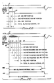
- Fig. 1B the timing waveform diagram is shown similar to that of Figs 1A, except that some noise or crosstalk 16 appears and remains on the ventricular channel at the time that the A-pulse is generated on the atrial channel.
- the generation of the A-pulse begins the first portion of the blanking interval, the absolute refractory portion.
- This absolute refractory portion is shown in Fig. 1B as a pulse 22, having a fixed width, "1AR" (for first absolute refractory).
- the termination of the first absolute refractory pulse 22 triggers the generation of a relative refractory pulse 24.
- This relative refractory pulse has a maximum width labeled "MRR" (for maximum relative refractory).
- the noise or crosstalk 16 appearing in the ventricular channel has not completely terminated during the relative refractory portion of the blanking interval.
- a burst of noise or crosstalk 20 is present during this relative refractory portion.
- the occurrence of this noise or crosstalk 20 causes the relative refractory portion 22 to be cut short, that is, to terminate prior to the maximum time permitted by the maximum relative refractory portion; and causes the absolute refractory pulse to again be triggered.
- This retriggering of the absolute refractory pulse is illustrated in Fig. 1B as a second absolute refractory pulse 26.
- This retriggered absolute refractory pulse 26 has a duration or width the same as the first absolute refractory pulse 22.
- a second relative refractory pulse 28 is generated.
- This second relative refractory pulse 28 continues for a prescribed time, MRR, at which time the pulse terminates. Because the noise or crosstalk on the ventricular channel no longer exists during the second relative refractory pulse 28, there is no further retriggering of the absolute refractory pulse.
- a blanking interval (BI) pulse 30 is generated that begins with the first triggering of the first absolute refractory pulse 22 and terminates at the conclusion of the last retriggered relative refractory pulse 28. That is, as seen in Fig.
- the blanking interval pulse 30 has a width that comprises the cumulative sum of the first absolute refractory pulse 22, or 1AR; the first relative refractory pulse 24 (which is a shortened pulse, and is therefore labeled "1RR ⁇ "); the second absolute refractory pulse 26, 2AR; and the second relative refractory pulse 28, 2RR.
- a maximum blanking interval pulse 32 defines the maximum time or width that the blanking interval pulse 30 may assume. That is, in the event that noise or crosstalk continues to occur on the ventricular channel, the blanking interval pulse continues to automatically adjust in length through the process described above (retriggering of the absolute refractory pulse followed by the relative refractory pulse).
- the present invention limits the blanking interval pulse 30 to assume a value that is the shorter of the maximum blanking interval pulse 32, or the cumulative sum of the absolute refractory pulse 22, the relative refractory pulse 24, and any retriggered absolute refractory pulses or relative refractory pulses.
- the maximum blanking interval pulse 32 be a programmable value that can assume any value up to the A-V interval, or some value less than the A-V interval.
- the MBI would be programmed to be a prescribed amount less than the AVI.
- the total length of the blanking interval pulse 30 is the cumulative sum of the various absolute refractory pulses and relative refractory pulses that are initially generated or subsequently retriggered. All but the last of the retriggered relative refractory pulses (that follow the retriggered absolute refractory pulses), will be shorter than their maximum length, depending upon when the crosstalk occurs within such relative refractory pulses.
- the length of the blanking interval pulse 30 (assuming a length less than the MBI) is not known in advance. For this reason, this embodiment is referred to as an asynchronous embodiment, meaning that the blanking interval pulse 30 assumes a length that is entirely a function of the noise or crosstalk that occurs on the ventricular channel.
- Figs. 2A, 2B, and 2C illustrate timing diagrams showing the manner in which an adjustable blanking period is generated in accordance with a synchronous embodiment of the present invention.
- the embodiment of the invention shown in Figs. 2A, 2B and 2C is termed "synchronous" because the adjustable blanking interval generated is always an integral number of clock periods, T, in length.
- T clock periods
- This blanking interval pulse is divided into a first absolute refractory portion and a second relative refractory portion, where each portion has a length T.
- T the total length of the blanking interval pulse 34 is 2T.
- Fig. 2B a situation is illustrated wherein there is a short burst of noise or crosstalk appearing on the ventricular channel subsequent to the delivery of an A-pulse (stimulation pulse) on the atrial channel.
- the delivery of the A-pulse on the atrial channel initiates the first absolute refractory portion of a blanking interval pulse 36.
- This first absolute refractory portion has a width or length T, the period of the clock signal that is used to generate the blanking interval pulse.
- the relative refractory portion begins.
- crosstalk or noise is present on the ventricular channel at this time.
- a second absolute refractory portion is immediately retriggered.
- the noise or crosstalk on the ventricular channel has subsided, and the relative refractory portion, also having a length T, ends. Because no further noise or crosstalk appears on the ventricular channel during the relative refractory portion following the second retriggered absolute refractory portion, the blanking interval terminates, having a total length of 3T.
- FIG. 2C another timing diagram of the present invention is illustrated for the situation where a long period of noise or crosstalk is present on the ventricular channel.
- the delivery of an A-pulse on the atrial channel initiates a first absolute refractory portion of a blanking interval pulse 38.
- This first absolute refractory portion the noise or crosstalk appearing on the ventricular channel is of no consequence, as the sensing circuits are refractory during this time and unable to sense any activity.
- This first absolute refractory portion has a length T.
- the noise or crosstalk is still present on the ventricular channel, thereby triggering a second absolute refractory portion, also having a length T.
- the noise or crosstalk is still present on the ventricular channel, thereby retriggering a third absolute refractory portion of length T.
- the crosstalk still exists on the ventricular channel, thereby retriggering a fourth absolute refractory portion of length T.
- the crosstalk or noise still persists on the ventricular channel, thereby retriggering a fifth absolute refractory portion of length T.
- the noise or crosstalk on the ventricular channel has finally subsided, thereby initiating a relative refractory portion of the blanking interval pulse.
- the blanking interval pulse 38 terminates at the conclusion of the relative refractory portion.
- the blanking interval pulse 38 has a total length of 6 clock periods, or 6T, comprising a first absolute refractory portion, a second retriggered absolute refractory portion, a third retriggered absolute refractory portion, a fourth retriggered absolute refractory portion, a fifth retriggered absolute refractory portion, and a final relative refractory portion.
- a maximum blanking interval pulse or MBI.
- MBI maximum blanking interval pulse
- the logic circuitry used to generate the blanking interval pulse causes the blanking interval pulse to equal the maximum blanking interval pulse.
- the logic circuitry used to generate the adjustable blanking interval pulse in accordance with the present invention causes the blanking interval pulse to be equal to the shorter of either the maximum blanking interval pulse (MBI) or the sum of the first absolute refractory portion, any retriggered absolute refractory portions, and a final relative refractory portion.
- the maximum blanking interval is a programmed value that is typically set to some value less than the A-V interval, AVI.
- the MBI could be equal to the AVI if no sensing on the ventricular channel were needed for a particular patient.
- the MBI would be programmably set to some increment or value less than the A-V interval, thereby providing some period of time during the A-V interval during which the sensing circuits of the ventricular channel are enabled to sense ventricular activity.
- FIG. 3 a block diagram of a dual chamber implantable pacemaker that includes the automatically adjustable blanking logic in accordance with the present invention is illustrated.
- This pacemaker includes an atrial generator 40 for generating atrial stimulation pulses (A-pulse) on an atrial channel 42.
- a V-pulse generator 44 generates V-pulses for delivery to the ventricle over a second ventricular channel 46.
- Coupled to the atrial channel 42 is an atrial sense amplifier 48, the output of which is directed to A-sense logic 50.
- the function of the A-sense logic 50 is to generate an appropriate logic signal(s) for delivery to the pacemaker control logic 52.
- a ventricular sense amplifier 54 coupled to the ventricular channel 46.
- V-Sense logic circuitry 56 The output of the ventricular sense amplifier 54 is directed to V-Sense logic circuitry 56.
- the function of the V-Sense logic 56 is to generate the appropriate logic signal(s) for delivery to the pacemaker control logic 52 indicating that activity has been sensed on the ventricular channel 46.
- Clock circuitry 58 generates an appropriate clock signal that is also directed to the pacemaker control logic 52.
- the pacemaker control logic 52 utilizing a clock signal generated by the clock circuitry 58, generates appropriate timing intervals, such as the A-V interval, during which the outputs of the A-sense logic 50 and/or the V-sense logic 56 are monitored in order to determine if appropriate activity is sensed on the respective atrial and ventricular channels. For example, if the pacemaker control logic 52 determines that no atrial activity has occurred, as determined by monitoring the A-sense input from the A-sense logic 50, within a prescribed time period, then an appropriate trigger signal is generated, identified as "A" in Fig. 3, for delivery to the A-pulse generator 40. This trigger signal A causes an A-pulse to be generated and delivered on the A-channel. If activity is sensed on the atrial channel within the prescribed time period, then the A trigger signal is not generated, and delivery of the A-pulse on the atrial channel is thereby inhibited.
- appropriate timing intervals such as the A-V interval
- the pacemaker control logic 52 determines that no activity has occurred in the ventricular channel 46 (which activity would indicate that the monitored ventricle has contracted), as determined by monitoring the V-sense input from the V-sense logic 56, within another prescribed time period (the AV interval), then another trigger signal is generated, identified as "V" in Fig. 3.
- the trigger signal V is delivered to the V-pulse generator 44, thereby causing a V-pulse to be generated and presented on the ventricular channel 46. If, on the other hand, activity is sensed on the ventricular channel within the prescribed AV interval, then the delivery of the V-trigger signal is inhibited. In this manner, the pacemaker control logic 52 delivers appropriate trigger pulses to the A-pulse generator 40 or the V-pulse generator 44, on demand, thereby maintaining a desired cardiac rhythm for the heart with which the pacemaker is used.
- automatically adjustable blanking logic circuitry 60 generates a blanking interval (BI) pulse that defines when activity sensed on the ventricular channel should be interpreted as an R-wave and when it should be interpreted as crosstalk.
- BI blanking interval
- This blanking interval pulse is presented to the pacemaker control logic, where it is used as described above in either Figs. 1A-1B or 2A-2C.
- no clock signal is required within the adjustable blanking logic circuitry 60.
- a clock signal would be delivered to the adjustable blanking logic circuitry 60 from the clock circuitry 58.
- the A trigger pulse delivered to the A-pulse generator 40 is also connected to the adjustable blanking logic circuit 60. It is this pulse, as explained above in the timing waveform diagrams of Figs. 1A-1B and 2A-2C that triggers the beginning of the blanking interval pulse.
- the absolute refractory portions of the blanking interval pulse, or signal, which absolute refractory portion is identified as a signal "AR" in Fig. 3, is presented to a power control circuit 62 so as to selectively enable or disable the V-sense amplifier 54.
- the power control circuit 62 removes power from the V-sense amplifier 54, thereby rendering the ventricular channel refractory during this period of time.
- the power control circuit 62 enables the V-sense amplifier 54, thereby allowing the V-sense amplifier 54 to sense activity occurring on the ventricular channel 46.
- any activity sensed during this time is interpreted as noise or crosstalk.
- the occurrence of such noise or crosstalk retriggers the absolute refractory portion of the blanking interval pulse in the manner described above.
- a stimulation pulse V-pulse
- an atrial channel blanking interval pulse that is divided into absolute and relative refractory portions. During the absolute refractory portions, no activity could be sensed on the atrial channel by the A-sense amplifier 48.
- any activity sensed on the atrial channel would be interpreted as crosstalk or noise, thereby retriggering the absolute refractory portion of the blanking interval pulse. Only after the relative refractory portion of the blanking interval pulse had terminated, could the activity sensed on the atrial channel be interpreted as a valid atrial event (e.g., a P-wave).
- a valid atrial event e.g., a P-wave
- Fig. 4A a simplified functional logic schematic diagram of the asynchronous embodiment of the present invention is shown.
- Fig. 4B illustrates a timing waveform diagram associated with the operation of the circuit of Fig. 4A.
- the trigger pulse, A is presented to one input of a two input OR gate 64.
- the output of the OR gate 64 is directed to a first one-shot circuit U1.
- This one-shot circuit U1 generates a pulse having a fixed length upon the occurrence of a positive transition of the input signal.
- the positive edge of the A trigger signal causes the output of the one-shot U1, identified as Q1, to generate a pulse 66 having width W1.
- This pulse 66 comprises the absolute refractory portion of the blanking interval pulse generated by the circuit of Fig. 4A.
- the Q1 output of the one-shot U1 passes through a series of invertor gates 68 with the output of the last gate providing the absolute refractory signal, AR. These gates 68 cause a slight delay from the time when the absolute refractory signal AR begins and the time the A trigger pulse was first generated. This slight delay is illustrated in Fig. 4B as the time d1.
- the inverted output of the first one-shot U1 is used to trigger a second one-shot U2. This second one-shot U2 generates the relative refractory portion of the blanking interval pulse.
- the trailing edge of the refractory pulse 66 thus triggers the one-shot U2, which one-shot generates another pulse 69 appearing at its Q2 output.
- the pulse 69 has a width W2.
- a pulse 70 appears at the output of the V-sense logic 56, indicating that activity has been sensed on the ventricular channel, the one-shot U2 is reset.
- This pulse 70 also passes through the OR gate 64 to cause the first one-shot U1 to be retriggered, thereby restarting the absolute refractory pulse 66.
- the total blanking interval pulse is the sum of the output of the first one-shot U1, the delayed output of the first one-shot U1, and the output of the second one-shot U2, as combined in a three-input OR gate 74.
- the introduction of the delay d1 in the absolute refractory portion of the pulse assures that the blanking interval pulse BI stays high during the entire period during which either the absolute refractory one-shot U1 or the relative refractory one-shot U2 is triggered.
- the blanking interval pulse BI comprises the sum of the refractory pulses 66, each having a width W1, as well as the relative refractory pulses 69, each of which may have a variable length depending upon when the V-sense pulse 70 occurs, except for the last relative refractory pulse, which has a length of W2.
- Fig. 5A illustrates a simplified functional logic diagram for a synchronous embodiment of the present invention, with Fig. 5B illustrating a timing waveform diagram that illustrates the operation of the circuit of Fig. 5A.
- the synchronous circuit of Fig. 5A includes 3 D-type flip-flops, U3, U4 and U5.
- Flip-flops U3 and U4 function as a shift register with flip-flop U3 normally being set to the zero state at each positive-going transition of the clock signal, CLK.
- Flip-flop U5 functions as a latch circuit which generates the blanking interval pulse BI.
- the occurrence of a trigger pulse, A causes the flip-flop U3 to be set to the one state.
- Flip-flop U3 remains set for one clock period, at which time flip-flop U4 is set by the shift-register action of the two flip-flops.
- Flip-flop U4 likewise remains set for one clock period. If no activity is sensed on the ventricular channel during the time that the flip-flop U4 is set, as is the case for the left-hand portion of Fig. 5B, a blanking interval pulse is generated by the flip-flop U5 having a total length of 2T, or 2 clock periods.
- the output of the AND gate 80 is coupled to the set input of flip-flop U3.
- the flipflop U3 is set.
- the occurrence of the VS signal is used to reset the flip-flop U4.
- the resetting of flip-flop U4 disables the AND gate 78, thereby causing the signal VS to be a very narrow "sliver" of a pulse having a duration determined largely by the propagation delay times of the gates 78, 79, and the reaction time of the flip-flop U4.
- the setting of flip-flop U3 restarts the absolute refractory pulse, and the above-described process repeats.
- the flip-flop U3 remains set until the beginning of the next clock period, at which time the flip-flop U4 is set.
- Flip-flop U4 remains set for one clock period, or until activity is sensed on the ventricular channel, as evidenced by the presence of a pulse 70, whichever occurs first.
- the absolute refractory flip-flop U3 is set a total of three times, once by the initial A trigger signal A, and twice by the occurrence of each V-sense pulse 70.
- the total blanking interval pulse comprises a pulse having a length equal to four clock periods, or 4T.
- Figs 6A depicts a simplified functional logic diagram of one embodiment of the V-sense logic 56 of Fig. 3.
- the output from the V-sense amplifier 54 is coupled to one input of a comparator circuit 90.
- the other input of the comparator circuit 90 is coupled to a threshold reference voltage V T .
- the output of the comparator circuit is connected to the positive transition input of a one-shot U6, having an output Q6 that comprises the V-sense signal 70.
- a pulse appears on the V-sense line.
- this pulse has a width w, although it is to be understood that other configurations could be used to generate an appropriate signal on the V-sense line that would serve the same function.
- the pulse 70 is generated whenever the amplified V-channel signal exceeds the threshold V T , and is not generated when the signal is less than the threshold V T .
- the value of the threshold V T may be a programmed value within the pacemaker which can be programmably set in order to adjust the sensitivity of this sense circuit to a desired level.
Landscapes
- Health & Medical Sciences (AREA)
- Cardiology (AREA)
- Heart & Thoracic Surgery (AREA)
- Life Sciences & Earth Sciences (AREA)
- Biophysics (AREA)
- Physiology (AREA)
- Engineering & Computer Science (AREA)
- Biomedical Technology (AREA)
- Nuclear Medicine, Radiotherapy & Molecular Imaging (AREA)
- Radiology & Medical Imaging (AREA)
- Animal Behavior & Ethology (AREA)
- General Health & Medical Sciences (AREA)
- Public Health (AREA)
- Veterinary Medicine (AREA)
- Electrotherapy Devices (AREA)
Applications Claiming Priority (2)
| Application Number | Priority Date | Filing Date | Title |
|---|---|---|---|
| US07/422,714 US4974589A (en) | 1989-10-17 | 1989-10-17 | Automatically adjustable blanking period for implantable pacemaker |
| US422714 | 1989-10-17 |
Publications (2)
| Publication Number | Publication Date |
|---|---|
| EP0423600A2 true EP0423600A2 (de) | 1991-04-24 |
| EP0423600A3 EP0423600A3 (en) | 1992-05-20 |
Family
ID=23676047
Family Applications (1)
| Application Number | Title | Priority Date | Filing Date |
|---|---|---|---|
| EP19900119351 Withdrawn EP0423600A3 (en) | 1989-10-17 | 1990-10-09 | Automatically adjustable blanking period for implantable pacemaker |
Country Status (4)
| Country | Link |
|---|---|
| US (1) | US4974589A (de) |
| EP (1) | EP0423600A3 (de) |
| JP (1) | JPH03139365A (de) |
| AU (1) | AU620774B2 (de) |
Families Citing this family (56)
| Publication number | Priority date | Publication date | Assignee | Title |
|---|---|---|---|---|
| US5117824A (en) * | 1990-11-14 | 1992-06-02 | Medtronic, Inc. | Apparatus for monitoring electrical physiologic signals |
| SE9200907D0 (sv) * | 1992-03-24 | 1992-03-24 | Siemens Elema Ab | Dubbelkammarpacemaker |
| SE9202826D0 (sv) * | 1992-09-30 | 1992-09-30 | Siemens Elema Ab | Hjaertstimulator |
| SE9202825D0 (sv) * | 1992-09-30 | 1992-09-30 | Siemens Elema Ab | Hjaertstimulator |
| SE9203171D0 (sv) * | 1992-10-28 | 1992-10-28 | Siemens Elema Ab | Anordning foer identifiering av atriell depolarisation |
| US5741308A (en) * | 1992-11-13 | 1998-04-21 | Pacesetter, Inc. | Dual-chamber implantable pacemaker and method of operating same for automatically setting the pacemaker's AV interval as a function of a natural measured conduction time |
| US5334220A (en) * | 1992-11-13 | 1994-08-02 | Siemens Pacesetter, Inc. | Dual-chamber implantable pacemaker having an adaptive AV interval that prevents ventricular fusion beats and method of operating same |
| US5340361A (en) * | 1992-11-13 | 1994-08-23 | Siemens Pacesetter, Inc. | Implantable pacemaker having adaptive AV interval adoptively shortened to assure ventricular pacing |
| US5814077A (en) * | 1992-11-13 | 1998-09-29 | Pacesetter, Inc. | Pacemaker and method of operating same that provides functional atrial cardiac pacing with ventricular support |
| FR2699413B1 (fr) * | 1992-12-23 | 1995-02-24 | Ela Medical Sa | Stimulateur cardiaque implantable. |
| US7280868B2 (en) * | 1994-08-16 | 2007-10-09 | Medtronic, Inc. | Capture management improvements |
| US5591214A (en) * | 1995-11-20 | 1997-01-07 | Telectronics Pacing Systems, Inc. | Pacemaker with automatic blanking period function |
| US5776167A (en) * | 1996-02-27 | 1998-07-07 | Pacesetter, Inc. | System and method for alleviating the effects of pacemaker crosstalk |
| US5792192A (en) * | 1997-04-19 | 1998-08-11 | Lu; Richard | Pacemaker with automatic mode switching using detection of hidden intrinsic cardiac pulses |
| FR2779353B1 (fr) | 1998-06-05 | 2000-07-13 | Ela Medical Sa | Dispositif medical implantable actif a gestion perfectionnee des periodes refractaires |
| US6128532A (en) * | 1998-09-15 | 2000-10-03 | Vitatron Medical, B.V. | Pacemaker with automatically controlled ventricular safety pulse |
| US6236882B1 (en) | 1999-07-14 | 2001-05-22 | Medtronic, Inc. | Noise rejection for monitoring ECG's |
| US6304778B1 (en) * | 1999-08-20 | 2001-10-16 | Cardiac Pacemakers, Inc. | Implantable defibrillators with programmable cross-chamber blanking |
| US6324422B1 (en) * | 1999-11-17 | 2001-11-27 | Pacesetter, Inc. | Methods for sensing arrhythmias in a pacemaker/defibrillator and a pacemaker/defibrillator programmed to implement the same |
| US7801606B2 (en) * | 2000-08-29 | 2010-09-21 | Cardiac Pacemakers, Inc. | Implantable pulse generator and method having adjustable signal blanking |
| US6829505B2 (en) | 2000-12-26 | 2004-12-07 | Cardiac Pacemakers, Inc. | System and method for cardiac rhythm management with synchronized pacing protection period |
| US6553258B2 (en) | 2000-12-26 | 2003-04-22 | Cardiac Pacemakers, Inc. | System and method for managing refractory periods in a cardiac rhythm management device with biventricular sensing |
| US6512952B2 (en) | 2000-12-26 | 2003-01-28 | Cardiac Pacemakers, Inc. | Method and apparatus for maintaining synchronized pacing |
| US6522921B2 (en) * | 2000-12-26 | 2003-02-18 | Cardiac Pacemakers, Inc. | System and method for eliminating cross-talk due to far-field signals |
| US6643547B2 (en) * | 2001-03-30 | 2003-11-04 | Cardiac Pacemakers, Inc. | Method and device for sensing atrial depolarizations during ventricular tachycardia |
| US6925329B1 (en) * | 2001-08-13 | 2005-08-02 | Pacesetter, Inc. | Automatic setting of cardiac operating parameters based upon capture threshold level |
| US6819955B2 (en) | 2001-10-09 | 2004-11-16 | Pacesetter, Inc. | Multi-chamber ventricular automatic capture method and apparatus for minimizing true and blanking period induced ventricular undersensing |
| US6757562B2 (en) * | 2001-10-25 | 2004-06-29 | Cardiac Pacemakers, Inc. | Reduction of left-ventricular offset interaction with tachyarrhythmia detection |
| US6731980B1 (en) * | 2001-10-29 | 2004-05-04 | Pacesetter, Inc. | System and method for automatically setting a pre-ventricular atrial blanking period |
| US6996437B2 (en) * | 2002-04-25 | 2006-02-07 | Medtronic, Inc. | Ventricular safety pacing in biventricular pacing |
| US7027858B2 (en) | 2002-09-11 | 2006-04-11 | Medtronic, Inc. | Methods and apparatus for cardiac R-wave sensing in a subcutaneous ECG waveform |
| ATE542566T1 (de) * | 2002-10-15 | 2012-02-15 | Medtronic Inc | Kanalselektive verdeckung für ein medizinisches system |
| AU2003285895A1 (en) * | 2002-10-15 | 2004-05-04 | Medtronic Inc. | Measuring a neurological event using clustering |
| US7016729B2 (en) * | 2002-12-30 | 2006-03-21 | Cardiac Pacemakers, Inc. | Reduction of interaction with tachyarrhythmia detection by negative offset pacing |
| DE102004017137A1 (de) * | 2004-04-01 | 2005-10-27 | Biotronik Gmbh & Co. Kg | Herzschrittmacher |
| US7616994B2 (en) * | 2004-05-24 | 2009-11-10 | Cardiac Pacemakers, Inc. | Fast post-antitachycardia pacing redetection algorithm |
| US7614533B2 (en) * | 2005-04-08 | 2009-11-10 | Boal Kimi L | Combination diaper bag and infant carrier |
| US8010209B2 (en) * | 2005-10-14 | 2011-08-30 | Nanostim, Inc. | Delivery system for implantable biostimulator |
| US9168383B2 (en) | 2005-10-14 | 2015-10-27 | Pacesetter, Inc. | Leadless cardiac pacemaker with conducted communication |
| US7715906B2 (en) * | 2007-06-04 | 2010-05-11 | Medtronic, Inc. | Method and apparatus for detecting noise in an implantable medical device |
| US8527068B2 (en) | 2009-02-02 | 2013-09-03 | Nanostim, Inc. | Leadless cardiac pacemaker with secondary fixation capability |
| US8447400B2 (en) | 2010-06-24 | 2013-05-21 | Pacesetter, Inc. | Systems and methods for use by an implantable medical device for controlling multi-site CRT pacing in the presence of atrial tachycardia |
| US8332033B2 (en) | 2010-06-24 | 2012-12-11 | Pacesetter, Inc. | Systems and methods for use by an implantable medical device for controlling multi-site CRT pacing in the presence of atrial tachycardia |
| US9060692B2 (en) | 2010-10-12 | 2015-06-23 | Pacesetter, Inc. | Temperature sensor for a leadless cardiac pacemaker |
| EP2627403A4 (de) | 2010-10-12 | 2014-03-26 | Nanostim Inc | Temperatursensor für einen bleifreien herzschrittmacher |
| US9020611B2 (en) | 2010-10-13 | 2015-04-28 | Pacesetter, Inc. | Leadless cardiac pacemaker with anti-unscrewing feature |
| EP2651494B1 (de) | 2010-12-13 | 2017-02-15 | Pacesetter, Inc. | Implantationskatheter |
| US9126032B2 (en) | 2010-12-13 | 2015-09-08 | Pacesetter, Inc. | Pacemaker retrieval systems and methods |
| CN103328040B (zh) | 2010-12-20 | 2016-09-14 | 内诺斯蒂姆股份有限公司 | 具有径向固定机构的无导线起搏器 |
| WO2013067496A2 (en) | 2011-11-04 | 2013-05-10 | Nanostim, Inc. | Leadless cardiac pacemaker with integral battery and redundant welds |
| US8805502B2 (en) * | 2011-12-27 | 2014-08-12 | Cardiac Pacemakers, Inc. | Managing cross therapy delivery in a multiple therapy implantable device |
| US9802054B2 (en) | 2012-08-01 | 2017-10-31 | Pacesetter, Inc. | Biostimulator circuit with flying cell |
| US9789317B2 (en) | 2015-02-26 | 2017-10-17 | Medtronic, Inc. | Pacing crosstalk detection |
| US20210251548A1 (en) * | 2020-02-14 | 2021-08-19 | Oregon State University | Low-power heart beat detection circuit architecture for body heat powered sensing |
| US20240226579A9 (en) * | 2022-10-25 | 2024-07-11 | Medtronic, Inc. | Noise identification and reduction for recording of signals with cardiac activity on spinal cord stimulation (scs) leads |
| CN121411177A (zh) * | 2025-12-29 | 2026-01-27 | 首都医科大学宣武医院 | 控制参数的调控方法、装置及存储介质 |
Family Cites Families (9)
| Publication number | Priority date | Publication date | Assignee | Title |
|---|---|---|---|---|
| DE2826054A1 (de) * | 1978-06-12 | 1979-12-13 | Leitner Enz Ruediger Von Dr | Herzschrittmacher |
| US4470418A (en) * | 1982-05-05 | 1984-09-11 | Cordis Corporation | Dual channel cardiac pacer isolation circuit |
| US4462407A (en) * | 1982-05-05 | 1984-07-31 | Cordis Corporation | Dual channel cardiac pacer isolation circuit |
| US4686988A (en) * | 1984-10-19 | 1987-08-18 | Sholder Jason A | Pacemaker system and method for measuring and monitoring cardiac activity and for determining and maintaining capture |
| US4726379A (en) * | 1985-11-14 | 1988-02-23 | Cardiac Control Systems, Inc. | Cardiac pacer with switching circuit for isolation |
| US4766901A (en) * | 1985-12-18 | 1988-08-30 | Telectronics N.V. | Rate responsive pacing system using the integrated evoked potential |
| US4788980A (en) * | 1986-07-18 | 1988-12-06 | Siemens-Pacesetter, Inc. | Pacemaker having PVC response and PMT terminating features |
| US4819643A (en) * | 1986-11-18 | 1989-04-11 | Mieczyslaw Mirowski | Method and apparatus for cardioverter/pacer featuring a blanked pacing channel and a rate detect channel with AGC |
| US4750495A (en) * | 1987-06-05 | 1988-06-14 | Medtronic, Inc. | Oxygen sensing pacemaker |
-
1989
- 1989-10-17 US US07/422,714 patent/US4974589A/en not_active Expired - Lifetime
-
1990
- 1990-07-06 AU AU58754/90A patent/AU620774B2/en not_active Ceased
- 1990-10-09 EP EP19900119351 patent/EP0423600A3/en not_active Withdrawn
- 1990-10-15 JP JP2277588A patent/JPH03139365A/ja active Granted
Also Published As
| Publication number | Publication date |
|---|---|
| JPH0453551B2 (de) | 1992-08-26 |
| AU620774B2 (en) | 1992-02-20 |
| JPH03139365A (ja) | 1991-06-13 |
| AU5875490A (en) | 1991-04-26 |
| EP0423600A3 (en) | 1992-05-20 |
| US4974589A (en) | 1990-12-04 |
Similar Documents
| Publication | Publication Date | Title |
|---|---|---|
| US4974589A (en) | Automatically adjustable blanking period for implantable pacemaker | |
| US4401119A (en) | Prolongation of timing intervals in response to ectopic heart beats in atrial and ventricular pacemakers | |
| US6553259B2 (en) | System and method of performing automatic capture in an implantable cardiac stimulation device | |
| AU616374B2 (en) | Atrial rate based programmable pacemaker with automatic mode switching means | |
| EP0113176B1 (de) | Mikroprozessor-gesteuerter Herzschrittmacher zur Vermeidung von durch den Schrittmacher verursachter Tachykardie | |
| US4407287A (en) | Atrial and ventricular-only pacemaker responsive to premature ventricular contractions | |
| US6731980B1 (en) | System and method for automatically setting a pre-ventricular atrial blanking period | |
| US4825870A (en) | Pacemaker having crosstalk protection feature | |
| US5086774A (en) | System and method for automatically compensating for latency conduction time in a programmable pacemaker | |
| US4781194A (en) | Heart pacemaker | |
| EP0559193B1 (de) | Implantierbarer Herzschrittmacher mit Hysteresefunktion bei Zweikammerbetriebsarten | |
| EP0526798B1 (de) | Frequenzadaptierender Zweikammer-Herzschrittmacher | |
| US7738955B2 (en) | System and method for ventricular pacing with AV interval modulation | |
| DE60030555T2 (de) | Vorrichtung zur anzeige der fehlpositionierung eines vorhofleiters | |
| EP0050038A2 (de) | Herzschrittmacher mit getrennten A-V-Intervallen für atrialsynchrone und atrialventrikulare sequentielle Betriebsarten | |
| US7424323B1 (en) | Implantable cardiac stimulation device providing autocapture with PMT avoidance and method | |
| EP0770408B1 (de) | Implantierbarer Herzschrittmacher | |
| EP2158002B1 (de) | Schrittmacher mit zwei kammern | |
| EP0241102B1 (de) | Herzschrittmacher | |
| CA1145408A (en) | Tachycardia sensing circuit for pacemaker | |
| EP0836867B1 (de) | Herzschrittmacher zur Vermeidung von Problemen beim Zusammenfall von Herzkammer-Reizungspulsen und Herzschlag | |
| US6862474B1 (en) | Implantable heart stimulator | |
| US8131366B2 (en) | Biventricular heart stimulator and method of controlling a biventricular heart stimulator | |
| US7299094B1 (en) | System and method for implementing autocapture within biventricular implantable cardiac stimulation systems | |
| US8233983B2 (en) | Implantable heart stimulator and method for operation thereof |
Legal Events
| Date | Code | Title | Description |
|---|---|---|---|
| PUAI | Public reference made under article 153(3) epc to a published international application that has entered the european phase |
Free format text: ORIGINAL CODE: 0009012 |
|
| AK | Designated contracting states |
Kind code of ref document: A2 Designated state(s): DE FR GB IT NL SE |
|
| PUAL | Search report despatched |
Free format text: ORIGINAL CODE: 0009013 |
|
| AK | Designated contracting states |
Kind code of ref document: A3 Designated state(s): DE FR GB IT NL SE |
|
| 17P | Request for examination filed |
Effective date: 19920708 |
|
| 17Q | First examination report despatched |
Effective date: 19941027 |
|
| RAP1 | Party data changed (applicant data changed or rights of an application transferred) |
Owner name: PACESETTER AB |
|
| STAA | Information on the status of an ep patent application or granted ep patent |
Free format text: STATUS: THE APPLICATION HAS BEEN WITHDRAWN |
|
| 18W | Application withdrawn |
Withdrawal date: 19950503 |