EP0836867B1 - Herzschrittmacher zur Vermeidung von Problemen beim Zusammenfall von Herzkammer-Reizungspulsen und Herzschlag - Google Patents
Herzschrittmacher zur Vermeidung von Problemen beim Zusammenfall von Herzkammer-Reizungspulsen und Herzschlag Download PDFInfo
- Publication number
- EP0836867B1 EP0836867B1 EP97117017A EP97117017A EP0836867B1 EP 0836867 B1 EP0836867 B1 EP 0836867B1 EP 97117017 A EP97117017 A EP 97117017A EP 97117017 A EP97117017 A EP 97117017A EP 0836867 B1 EP0836867 B1 EP 0836867B1
- Authority
- EP
- European Patent Office
- Prior art keywords
- stimulating device
- qrs
- heart
- filtered
- interval
- Prior art date
- Legal status (The legal status is an assumption and is not a legal conclusion. Google has not performed a legal analysis and makes no representation as to the accuracy of the status listed.)
- Expired - Lifetime
Links
- 230000004936 stimulating effect Effects 0.000 title claims description 23
- 206010047289 Ventricular extrasystoles Diseases 0.000 title description 13
- 230000000638 stimulation Effects 0.000 claims description 30
- 230000000763 evoking effect Effects 0.000 claims description 10
- 238000001514 detection method Methods 0.000 description 34
- 238000000718 qrs complex Methods 0.000 description 16
- 230000004044 response Effects 0.000 description 6
- 230000005764 inhibitory process Effects 0.000 description 5
- 230000000694 effects Effects 0.000 description 4
- 230000002035 prolonged effect Effects 0.000 description 4
- 230000034225 regulation of ventricular cardiomyocyte membrane depolarization Effects 0.000 description 4
- 230000004913 activation Effects 0.000 description 3
- 230000000747 cardiac effect Effects 0.000 description 3
- 230000005540 biological transmission Effects 0.000 description 2
- 230000001934 delay Effects 0.000 description 2
- 238000005265 energy consumption Methods 0.000 description 2
- 210000005003 heart tissue Anatomy 0.000 description 2
- 230000002269 spontaneous effect Effects 0.000 description 2
- 210000005242 cardiac chamber Anatomy 0.000 description 1
- 230000001419 dependent effect Effects 0.000 description 1
- 238000010586 diagram Methods 0.000 description 1
- 238000001914 filtration Methods 0.000 description 1
- 238000012986 modification Methods 0.000 description 1
- 230000004048 modification Effects 0.000 description 1
- 210000004165 myocardium Anatomy 0.000 description 1
- 230000002028 premature Effects 0.000 description 1
- 230000004213 regulation of atrial cardiomyocyte membrane depolarization Effects 0.000 description 1
- 230000033764 rhythmic process Effects 0.000 description 1
- 230000035945 sensitivity Effects 0.000 description 1
- 230000002861 ventricular Effects 0.000 description 1
Images
Classifications
-
- A—HUMAN NECESSITIES
- A61—MEDICAL OR VETERINARY SCIENCE; HYGIENE
- A61N—ELECTROTHERAPY; MAGNETOTHERAPY; RADIATION THERAPY; ULTRASOUND THERAPY
- A61N1/00—Electrotherapy; Circuits therefor
- A61N1/18—Applying electric currents by contact electrodes
- A61N1/32—Applying electric currents by contact electrodes alternating or intermittent currents
- A61N1/36—Applying electric currents by contact electrodes alternating or intermittent currents for stimulation
- A61N1/362—Heart stimulators
- A61N1/37—Monitoring; Protecting
- A61N1/371—Capture, i.e. successful stimulation
- A61N1/3712—Auto-capture, i.e. automatic adjustment of the stimulation threshold
Definitions
- the present invention relates to a heart stimulating device having a capability to inhibit stimulation in case of natural activity of a patient's heart.
- the invention particularly concerns the capability of detecting intrinsic events in order to favour intrinsic heart activity and to avoid fusion beats.
- Fusion beat generally refers to a situation where atrial or ventricular depolarization starts from two different positions in the heart. Such a situation arises when a natural heart beat occurs simultaneously with an electrical stimulation pulse from a heart stimulating device and they both contribute to the depolarisation of a heart chamber.
- fusion beats or pseudofusion beats present a particular problem, since intrinsic events are to be favoured and stimulation energy is to be saved until really needed. That way the longevity of a battery powered heart stimulating device is improved.
- IEGM An abbreviation for intracardiac electrogram.
- IEGM signals are emitted by active cardiac tissue and sensed through electrodes placed on or within the heart.
- QRS or QRS complex The ventricular depolarization as seen on the electro cardiogram or in the IEGM signals.
- Intrinsic Inherent or belonging to the heart itself.
- An intrinsic beat is a naturally occurring heartbeat.
- R wave an intrinsic ventricular event.
- R refers to the entire intrinsic QRS complex.
- Evoked response The electrical activation of the myocardium by a pacemaker output pulse. The ability of cardiac tissue to respond depends on its activity state. Fusion beat: the pacemaker impulse appears close to a spontaneous QRS complex and partly affects the ventricular depolarization.
- Pseudofusion beat the pacemaker impulse appears within a spontaneous QRS complex and does not affects the ventricular depolarization. May be referred to as simply a fusion beat in contexts where problems related thereto are similar to those of regular fusion beats.
- Hysteresis A programmable feature in some demand pacemakers which allows programming of a hysteresis escape rate lower than the programmed base rate. Hysteresis may be accomplished by prolonging the pacing interval following a sensed intrinsic beat. Escape interval, basic interval, or basic escape interval: The period, typically in the order of 1000 milliseconds, between a sensed intrinsic cardiac event or a stimulation pulse output and the next pacemaker output pulse.
- IEGM signals are sensed via a lead and electrode arrangement.
- Intrinsic and stimulated QRS indications in the IEGM signals are monitored by sensing means in the pacemaker. As long as intrinsic QRS complexes are detected at an acceptable rate by the sensing means, the pacemaker inhibits the stimulation pulses.
- a timer is started in the pacemaker. If no new QRS is detected within a predetermined basic interval of the timer, a stimulation pulse to the heart is output by a pulse generator in the pacemaker.
- the QRS detections are performed after a band pass filter that delays the IEGM signals.
- a particular object is to avoid fusion beats more effectively.
- Another object of the invention is to provide means for avoiding excessive energy in the stimulation pulses.
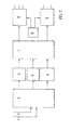
- Fig. 1 shows a block diagram of a heart stimulating device according to one embodiment of the invention including sensing inputs, a sense amplifier, detection means, logic means, pulse output means, and charge means.
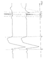
- Fig. 2 shows two examples of IEGM signals input to the device of Fig. 1, illustrating situations where a fusion beat occurs due to filter delay in sensing an R wave and where stimulation is inhibited according to the invention as a result of a detected competing intrinsic event, respectively.
- Fig. 1 The described type of device is operable to inhibit stimulation to favour intrinsic events.
- the device has sensing inputs 1, 2 that feed IEGM signals to a sense amplifier 3.
- the sensing inputs 1, 2 are typically connected to a lead (not shown) and a cardiac electrode (not shown) which provide the IEGM signals to the heart stimulating device.
- the sense amplifier provides amplified IEGM signals to three detection means 4, 5, 6.
- a filtered first R wave detection means 4 is operable to detect intrinsic QRS complexes. It could also have the ability to detect P waves if processing thereof is to be performed by the heart stimulating device.
- a filtered evoked response (ER) detection means 5 is operable to detect stimulation-evoked QRS complexes.
- a non-filtered second R wave detection means 6 is operable to detect intrinsic QRS complexes.
- Each of the detection means 4, 5, 6 is connected to a logic means 7 to which it indicates a detected QRS complex.
- the filtered first R wave detection means 4 includes a band pass filter for filtering the amplified IEGM signals before they are used for detection of QRS complexes.
- the band pass filter there is however inevitably a delay or transfer time for the signals.
- a delay may be 20 ms.
- the said filter delay time may be the most significant one, all unintended signal delays in the heart stimulating device could be a problem when aiming to avoid fusion beats or the negative consequences thereof.
- An example of such a delay is the transfer time of the stimulation inhibition signal.
- the logic means controls a pace pulse generator 8 and a back-up pulse generator 9 which are operable to transmit stimulation pulses to a patient's heart.
- the pulse generators 8, 9 may be connected to via the same lead (not shown) to the same cardiac electrode (not shown) as the sense amplifier 3.
- a charge means 10 is connected to both pulse generators 8, 9 to provide them with the necessary stimulation energy.
- the logic means 7 includes timing means in order to stimulate the patient's heart at an appropriate rate when needed and to distinguish between the different detections made in the detection means.
- the logic means 7 may also deactivate any of the detection means 4, 5, 6 during selected time intervals.
- the delay in the filtered first R wave detection means 4 implies that a decision by the logic means 7 to initiate a stimulation pulse can only be based on signals representing a situation up until present minus the filter delay.
- the logic means 7 has to decide, after a certain time interval has passed since a detected QRS complex, whether a stimulation pulse should be transmitted or not.
- the said time interval will be referred to as a basic interval.
- the non-filtered R wave detection means 6 gives an earlier detection of a QRS complex, but suffers from a higher sensitivity to noise. As will be further described below a combination of the two R wave detection means 4, 6 is particularly advantageous.
- fig. 2 which includes an upper IEGM curve including one stimulation-evoked and one intrinsic QRS complex and a lower IEGM curve including first a stimulation-evoked QRS complex and then a fusion beat, i.e., an intrinsic event wherein a stimulation pulse has been transmitted.
- the dotted line indicates an expected curve shape in the absence of an intrinsic heart activity.
- FIG. 2 further shows a time line on which points in time t 0 , t 1 , t 2 , t 3 , t 4 , and t 5 have been marked with dashed lines to indicate a transmission of a stimulation pulse to evoke a QRS (t 0 ), an end point for detecting evoked response subsequent to a stimulation (t 1 ), an end of a basic interval simultaneously with an intrinsic QRS complex (t 2 ), the activation of the non-filtered detection means (t 3 ), the instant when the non-filtered detection means detects the intrinsic event (t 4 ), and an end of a prolonged basic interval (t 5 ), respectively.
- the inventive heart stimulating device In order to illustrate the operation of the inventive heart stimulating device a sequence to be described is assumed to start by the transmission of a stimulation pulse at to. Then the evoked response detection means 5 is activated after a predetermined delay to detect evoked response until t 1 . If no evoked response has been detected, the heart stimulating device generally emits a back-up pulse.
- the upper IEGM curve indicates an intrinsic event and an inhibition of stimulation, while the lower curve indicates a fusion beat.
- the non-filtered detection means is active for only about 20 ms from t 3 until the end of the basic interval at t 2 or only until a detection of an intrinsic event at t 4 . If an intrinsic event is detected in the non-filtered detection means between t 3 and t 2 , the basic interval is prolonged until t 5 , so that the IEGM signal containing the intrinsic QRS indication will have time to travel through the filter of the filtered R wave detection means. For this reason, an extension interval from t 2 to t 5 can be set equal or greater than the filter delay time. Alternatively, the point in time t 5 when the prolonged escape interval ends can be set by t 4 , i.e., the point in time at which the non-filtered detection means detects an intrinsic QRS.
- a subsequent basic interval is started at t 2 and the length thereof may be set equal to the preceding one in order to maintain a pacing rate or may be set so that hysteresis is achieved which favours intrinsic events.
- the safe operation of the inventive heart stimulating device is effectively maintained since a basic interval would be prolonged mainly in exceptional situations and the prolongation would be very small compared to the length of a typical heart cycle.
- a typical length of the basic interval is 850 ms. It could have an adjustment range between 500 and 1333 ms.
- the band-pass filter delay, which is to be compensated for, in the filtered R wave detection means is typically 20 ms. Consequently, following a detection in the non-filtered R wave detection means of an intrinsic QRS, the basic interval should typically be 20 ms or slightly more immediately after the end of the basic interval or, if a varying timing is not unsuitable, after the detection in the non-filtered R wave detection means.
- the activation time of the non-filtered R wave detection means has to precede the "blind" interval of the corresponding filtered means before the end of the basic interval. Therefore, it will typically be at least 20 ms or slightly more before the end of the basic interval. However, since the non-filtered R wave detection means only controls the prolongation of the basic interval and not the stimulation inhibition itself, it could be longer. For energy saving reasons, it is kept short.
- fig. 2 is not drawn to scale but rather illustrates a relative timing of typical phenomena monitored through the IEGM signals.
Landscapes
- Health & Medical Sciences (AREA)
- Cardiology (AREA)
- Heart & Thoracic Surgery (AREA)
- Engineering & Computer Science (AREA)
- Biomedical Technology (AREA)
- Nuclear Medicine, Radiotherapy & Molecular Imaging (AREA)
- Radiology & Medical Imaging (AREA)
- Life Sciences & Earth Sciences (AREA)
- Animal Behavior & Ethology (AREA)
- General Health & Medical Sciences (AREA)
- Public Health (AREA)
- Veterinary Medicine (AREA)
- Electrotherapy Devices (AREA)
- Percussion Or Vibration Massage (AREA)
Claims (7)
- Herzstimulationsvorrichtung enthaltend:dadurch gekennzeichnet, dasseine Impulsgeneratorvorrichtung (8, 9), ausgelegt für die Lieferung von Stimulationsimpulsen zum Herz eines Patienten und mit einem Grundauslöseintervall,eine Abfühlvorrichtung (3, 4, 5) mit Filterung, ausgelegt zum Abfühlen von QRS-Anzeigen in IEGM-Signalen,eine Steuervorrichtung (7), ausgelegt zum Steuern der Impulsgeneratorvorrichtung (8, 9),
die genannte Vorrichtung ferner eine Abfühlvorrichtung (3, 6) ohne Filterung enthält, ausgelegt zum Abfühlen von QRS-Anzeigen in den IEGM-Signalen,
wobei die genannte Steuervorrichtung (7) ausgelegt ist vor einem Ende des genannten Grundauslöseintervalls die genannte Abfühlvorrichtung ohne Filterung zu aktivieren und ausgelegt ist, das genannte Grundauslöseintervall um ein vorbestimmtes Verlängerungsintervall zu verlängern, falls die genannte Abfühlvorrichtung (3, 6) ohne Filterung eine QRS-Anzeige abfühlt, wenn sie aktiviert ist. - Herzstimulationsvorrichtung nach Anspruch 1, wobei das Verlängerungsintervall fest ist und annähernd gleich oder größer als eine Filterverzögerung in der genannten Abfühlvorrichtung (3, 4, 5) mit Filterung ist.
- Herzstimulationsvorrichtung nach Anspruch 1, wobei die genannte Steuervorrichtung ausgelegt ist, die Länge des genannten Verlängerungsintervalls abhängig von dem Augenblick zu bestimmen, bei dem die Abfühlvorrichtung (3, 6) ohne Filterung eine QRS-Anzeige abfühlt.
- Herzstimulationsvorrichtung nach Anspruch 3, wobei das Verlängerungsintervall annähernd gleich einer Filterverzögerungszeit in der Abfühlvorrichtung (3, 4, 5) mit Filterung minus einem Rest des Grundauslöseintervalls bei dem Augenblick ist, bei dem die Abfühlvorrichtung (3, 6) ohne Filterung eine QRS-Anzeige abfühlt.
- Herzstimulationsvorrichtung nach einem der Ansprüche 1 bis 4, wobei die genannte Steuervorrichtung ausgelegt ist, die Länge des genannten Grundauslöseintervalls abhängig davon zu bestimmen, ob das passierte Ereignis innerlich oder durch Stimulation evoziert war.
- Herzstimulationsvorrichtung nach einem der Ansprüche 1 bis 5, wobei die genannte Steuervorrichtung (7) ausgelegt ist; die Abfühlvorrichtung (3, 6) ohne Filterung zu aktivieren, nachdem wenigstens 95% des Grundauslöseintervalls verstrichen sind.
- Herzstimulationsvorrichtung nach einem der Ansprüche 1 bis 5, wobei die genannte Steuervorrichtung (7) ausgelegt ist die Abfühlvorrichtung (3, 6) ohne Filterung 20 ms oder weniger zu aktivieren, bevor das Grundauslöseintervall geendet hat.
Applications Claiming Priority (2)
| Application Number | Priority Date | Filing Date | Title |
|---|---|---|---|
| SE9603865A SE9603865D0 (sv) | 1996-10-21 | 1996-10-21 | Heart stimulating device |
| SE9603865 | 1996-10-21 |
Publications (2)
| Publication Number | Publication Date |
|---|---|
| EP0836867A1 EP0836867A1 (de) | 1998-04-22 |
| EP0836867B1 true EP0836867B1 (de) | 2004-03-17 |
Family
ID=20404338
Family Applications (1)
| Application Number | Title | Priority Date | Filing Date |
|---|---|---|---|
| EP97117017A Expired - Lifetime EP0836867B1 (de) | 1996-10-21 | 1997-10-01 | Herzschrittmacher zur Vermeidung von Problemen beim Zusammenfall von Herzkammer-Reizungspulsen und Herzschlag |
Country Status (5)
| Country | Link |
|---|---|
| US (1) | US5836984A (de) |
| EP (1) | EP0836867B1 (de) |
| JP (1) | JPH10127781A (de) |
| DE (1) | DE69728107T2 (de) |
| SE (1) | SE9603865D0 (de) |
Families Citing this family (9)
| Publication number | Priority date | Publication date | Assignee | Title |
|---|---|---|---|---|
| US6038474A (en) * | 1999-03-02 | 2000-03-14 | Cardiac Pacemakers, Inc. | Pseudo-fusion management during automatic capture verification |
| US6850800B1 (en) | 2001-04-18 | 2005-02-01 | St. Jude Medical Ab | Evoked response detector, averaging the value of the amplitude of the picked-up electrode signal |
| US7006869B2 (en) | 2001-09-10 | 2006-02-28 | Pacesetter, Inc. | Method and device for enhanced capture tracking by discrimination of fusion beats |
| US6950704B1 (en) * | 2001-11-01 | 2005-09-27 | Pacesetter, Inc. | Use of ER signal variability for fusion detection and response in ventricular and atrial autocapture algorithms |
| US20040215277A1 (en) * | 2003-04-25 | 2004-10-28 | Peter Oosterhoff | Dynamic pacing interval extension for detection of intrinsic ventricular activity |
| US7957801B2 (en) | 2003-04-25 | 2011-06-07 | Medtronic, Inc. | Dynamic pacing interval extension for detection of intrinsic ventricular activity |
| US10328266B2 (en) | 2012-05-31 | 2019-06-25 | Zoll Medical Corporation | External pacing device with discomfort management |
| JP6836833B2 (ja) | 2012-05-31 | 2021-03-03 | ゾール メディカル コーポレイションZOLL Medical Corporation | 外部ペーシングを有する医療モニタリングおよび治療装置 |
| US11097107B2 (en) | 2012-05-31 | 2021-08-24 | Zoll Medical Corporation | External pacing device with discomfort management |
Family Cites Families (2)
| Publication number | Priority date | Publication date | Assignee | Title |
|---|---|---|---|---|
| US4969467A (en) * | 1988-03-25 | 1990-11-13 | Telectronics N.V. | Pacemaker with improved automatic output regulation |
| US5351696A (en) * | 1993-04-23 | 1994-10-04 | Medtronic, Inc. | Method and apparatus for intracardiac electrogram morphologic analysis |
-
1996
- 1996-10-21 SE SE9603865A patent/SE9603865D0/xx unknown
-
1997
- 1997-10-01 EP EP97117017A patent/EP0836867B1/de not_active Expired - Lifetime
- 1997-10-01 DE DE69728107T patent/DE69728107T2/de not_active Expired - Fee Related
- 1997-10-20 US US08/954,688 patent/US5836984A/en not_active Expired - Lifetime
- 1997-10-21 JP JP9288368A patent/JPH10127781A/ja active Pending
Also Published As
| Publication number | Publication date |
|---|---|
| DE69728107D1 (de) | 2004-04-22 |
| SE9603865D0 (sv) | 1996-10-21 |
| JPH10127781A (ja) | 1998-05-19 |
| DE69728107T2 (de) | 2005-01-27 |
| US5836984A (en) | 1998-11-17 |
| EP0836867A1 (de) | 1998-04-22 |
Similar Documents
| Publication | Publication Date | Title |
|---|---|---|
| US5861008A (en) | Heart stimulating device with stimulation energy responsive to detected noise | |
| US4343311A (en) | Atrial refractory control for R-wave rejection in pacemakers | |
| US4967746A (en) | Dual chamber pacemaker with adjustable blanking and V-A extension | |
| US6275731B1 (en) | Pseudo-fusion management during automatic capture verification | |
| US8046061B2 (en) | System and method for preventing recurrence of atrial tachyarrhythmia | |
| EP0201990B1 (de) | Herzschrittmacher mit Anpassungsmöglichkeiten an den Zustand des Herzvorhofes | |
| EP1051223B1 (de) | System zum einleiten von herzkammerflimmern unter verwendung von nahfeldwellenabtastung | |
| EP0765177B1 (de) | Vorrichtung zum steuern eines herzschrittmachers während der automatischen feststellung des ansprechens des herzens auf die stimulation | |
| EP0423600A2 (de) | Herzschrittmacher mit Selbstanpassung der Austastzeit | |
| US4825870A (en) | Pacemaker having crosstalk protection feature | |
| EP0680364A1 (de) | Verfahren und system auf der basis von herzwandbewegungen | |
| JPH09506539A (ja) | 心房および心室独立性を有する2連チャンバ・ペーシング | |
| EP0703804A1 (de) | Implantierbarer kardiovertierer/defibrillator mit einer sich anpassenden refraktärzeit | |
| EP1339454B1 (de) | Unterscheidung zwischen gültigen und ungültigen detektierten herzsignalen | |
| EP0770408B1 (de) | Implantierbarer Herzschrittmacher | |
| US5836984A (en) | Heart stimulating device | |
| EP0237767B1 (de) | Taktempfindliche Stimulierung mit Benutzung des ventrikulären Gradienten | |
| US6738665B2 (en) | Detection of late atrial extrasystoles in an active implantable medical device such as pacemaker defibrillator, cardiovertor and/or multisite device | |
| EP0241102B1 (de) | Herzschrittmacher | |
| JPH0649078B2 (ja) | プログラマブルで自動式の植え込み可能なカージオバータ/デフィブリレータおよびペースメーカシステム | |
| US7463925B2 (en) | Methods and systems for promoting ventricular pacing | |
| US6952609B1 (en) | Cardiac stimulating device | |
| JPS6151903B2 (de) |
Legal Events
| Date | Code | Title | Description |
|---|---|---|---|
| PUAI | Public reference made under article 153(3) epc to a published international application that has entered the european phase |
Free format text: ORIGINAL CODE: 0009012 |
|
| AK | Designated contracting states |
Kind code of ref document: A1 Designated state(s): DE ES FR GB IT NL |
|
| 17P | Request for examination filed |
Effective date: 19981022 |
|
| AKX | Designation fees paid |
Free format text: DE ES FR GB IT NL |
|
| RBV | Designated contracting states (corrected) |
Designated state(s): DE ES FR GB IT NL |
|
| RAP1 | Party data changed (applicant data changed or rights of an application transferred) |
Owner name: ST. JUDE MEDICAL AB |
|
| GRAP | Despatch of communication of intention to grant a patent |
Free format text: ORIGINAL CODE: EPIDOSNIGR1 |
|
| GRAS | Grant fee paid |
Free format text: ORIGINAL CODE: EPIDOSNIGR3 |
|
| GRAA | (expected) grant |
Free format text: ORIGINAL CODE: 0009210 |
|
| AK | Designated contracting states |
Kind code of ref document: B1 Designated state(s): DE ES FR GB IT NL |
|
| PG25 | Lapsed in a contracting state [announced via postgrant information from national office to epo] |
Ref country code: NL Free format text: LAPSE BECAUSE OF FAILURE TO SUBMIT A TRANSLATION OF THE DESCRIPTION OR TO PAY THE FEE WITHIN THE PRESCRIBED TIME-LIMIT Effective date: 20040317 |
|
| REG | Reference to a national code |
Ref country code: GB Ref legal event code: FG4D |
|
| REF | Corresponds to: |
Ref document number: 69728107 Country of ref document: DE Date of ref document: 20040422 Kind code of ref document: P |
|
| PG25 | Lapsed in a contracting state [announced via postgrant information from national office to epo] |
Ref country code: ES Free format text: LAPSE BECAUSE OF FAILURE TO SUBMIT A TRANSLATION OF THE DESCRIPTION OR TO PAY THE FEE WITHIN THE PRESCRIBED TIME-LIMIT Effective date: 20040628 |
|
| NLV1 | Nl: lapsed or annulled due to failure to fulfill the requirements of art. 29p and 29m of the patents act | ||
| PG25 | Lapsed in a contracting state [announced via postgrant information from national office to epo] |
Ref country code: GB Free format text: LAPSE BECAUSE OF NON-PAYMENT OF DUE FEES Effective date: 20041001 |
|
| ET | Fr: translation filed | ||
| PLBE | No opposition filed within time limit |
Free format text: ORIGINAL CODE: 0009261 |
|
| STAA | Information on the status of an ep patent application or granted ep patent |
Free format text: STATUS: NO OPPOSITION FILED WITHIN TIME LIMIT |
|
| 26N | No opposition filed |
Effective date: 20041220 |
|
| GBPC | Gb: european patent ceased through non-payment of renewal fee |
Effective date: 20041001 |
|
| PGFP | Annual fee paid to national office [announced via postgrant information from national office to epo] |
Ref country code: DE Payment date: 20061025 Year of fee payment: 10 |
|
| PGFP | Annual fee paid to national office [announced via postgrant information from national office to epo] |
Ref country code: IT Payment date: 20061031 Year of fee payment: 10 |
|
| PG25 | Lapsed in a contracting state [announced via postgrant information from national office to epo] |
Ref country code: DE Free format text: LAPSE BECAUSE OF NON-PAYMENT OF DUE FEES Effective date: 20080501 |
|
| REG | Reference to a national code |
Ref country code: FR Ref legal event code: ST Effective date: 20080630 |
|
| PGFP | Annual fee paid to national office [announced via postgrant information from national office to epo] |
Ref country code: FR Payment date: 20060929 Year of fee payment: 10 |
|
| PG25 | Lapsed in a contracting state [announced via postgrant information from national office to epo] |
Ref country code: FR Free format text: LAPSE BECAUSE OF NON-PAYMENT OF DUE FEES Effective date: 20071031 |
|
| PG25 | Lapsed in a contracting state [announced via postgrant information from national office to epo] |
Ref country code: IT Free format text: LAPSE BECAUSE OF NON-PAYMENT OF DUE FEES Effective date: 20071001 |