EP0423876A1 - Verfahren zum katalytischen Kracken eines Kohlenwasserstofföls - Google Patents
Verfahren zum katalytischen Kracken eines Kohlenwasserstofföls Download PDFInfo
- Publication number
- EP0423876A1 EP0423876A1 EP90202703A EP90202703A EP0423876A1 EP 0423876 A1 EP0423876 A1 EP 0423876A1 EP 90202703 A EP90202703 A EP 90202703A EP 90202703 A EP90202703 A EP 90202703A EP 0423876 A1 EP0423876 A1 EP 0423876A1
- Authority
- EP
- European Patent Office
- Prior art keywords
- process according
- hydrocarbon oil
- gas
- supply means
- reactor
- Prior art date
- Legal status (The legal status is an assumption and is not a legal conclusion. Google has not performed a legal analysis and makes no representation as to the accuracy of the status listed.)
- Granted
Links
- 239000004215 Carbon black (E152) Substances 0.000 title claims abstract description 49
- 229930195733 hydrocarbon Natural products 0.000 title claims abstract description 49
- 150000002430 hydrocarbons Chemical class 0.000 title claims abstract description 49
- 238000000034 method Methods 0.000 title claims abstract description 39
- 238000004523 catalytic cracking Methods 0.000 title claims abstract description 9
- 239000000203 mixture Substances 0.000 claims abstract description 13
- 239000003054 catalyst Substances 0.000 claims description 14
- 239000002245 particle Substances 0.000 claims description 11
- 238000011144 upstream manufacturing Methods 0.000 claims description 8
- 239000003921 oil Substances 0.000 description 37
- 239000007789 gas Substances 0.000 description 21
- 238000005243 fluidization Methods 0.000 description 7
- 229910021536 Zeolite Inorganic materials 0.000 description 2
- HNPSIPDUKPIQMN-UHFFFAOYSA-N dioxosilane;oxo(oxoalumanyloxy)alumane Chemical compound O=[Si]=O.O=[Al]O[Al]=O HNPSIPDUKPIQMN-UHFFFAOYSA-N 0.000 description 2
- 238000004231 fluid catalytic cracking Methods 0.000 description 2
- 239000010457 zeolite Substances 0.000 description 2
- OKTJSMMVPCPJKN-UHFFFAOYSA-N Carbon Chemical compound [C] OKTJSMMVPCPJKN-UHFFFAOYSA-N 0.000 description 1
- 229910052799 carbon Inorganic materials 0.000 description 1
- 125000004432 carbon atom Chemical group C* 0.000 description 1
- 239000012159 carrier gas Substances 0.000 description 1
- 239000000571 coke Substances 0.000 description 1
- -1 however Substances 0.000 description 1
- 239000003079 shale oil Substances 0.000 description 1
- 239000002002 slurry Substances 0.000 description 1
Images

Classifications
-
- C—CHEMISTRY; METALLURGY
- C10—PETROLEUM, GAS OR COKE INDUSTRIES; TECHNICAL GASES CONTAINING CARBON MONOXIDE; FUELS; LUBRICANTS; PEAT
- C10G—CRACKING HYDROCARBON OILS; PRODUCTION OF LIQUID HYDROCARBON MIXTURES, e.g. BY DESTRUCTIVE HYDROGENATION, OLIGOMERISATION, POLYMERISATION; RECOVERY OF HYDROCARBON OILS FROM OIL-SHALE, OIL-SAND, OR GASES; REFINING MIXTURES MAINLY CONSISTING OF HYDROCARBONS; REFORMING OF NAPHTHA; MINERAL WAXES
- C10G11/00—Catalytic cracking, in the absence of hydrogen, of hydrocarbon oils
- C10G11/20—Catalytic cracking, in the absence of hydrogen, of hydrocarbon oils by direct contact with inert heated gases or vapours
-
- B—PERFORMING OPERATIONS; TRANSPORTING
- B01—PHYSICAL OR CHEMICAL PROCESSES OR APPARATUS IN GENERAL
- B01J—CHEMICAL OR PHYSICAL PROCESSES, e.g. CATALYSIS OR COLLOID CHEMISTRY; THEIR RELEVANT APPARATUS
- B01J8/00—Chemical or physical processes in general, conducted in the presence of fluids and solid particles; Apparatus for such processes
- B01J8/08—Chemical or physical processes in general, conducted in the presence of fluids and solid particles; Apparatus for such processes with moving particles
- B01J8/085—Feeding reactive fluids
-
- B—PERFORMING OPERATIONS; TRANSPORTING
- B01—PHYSICAL OR CHEMICAL PROCESSES OR APPARATUS IN GENERAL
- B01J—CHEMICAL OR PHYSICAL PROCESSES, e.g. CATALYSIS OR COLLOID CHEMISTRY; THEIR RELEVANT APPARATUS
- B01J8/00—Chemical or physical processes in general, conducted in the presence of fluids and solid particles; Apparatus for such processes
- B01J8/18—Chemical or physical processes in general, conducted in the presence of fluids and solid particles; Apparatus for such processes with fluidised particles
- B01J8/20—Chemical or physical processes in general, conducted in the presence of fluids and solid particles; Apparatus for such processes with fluidised particles with liquid as a fluidising medium
- B01J8/22—Chemical or physical processes in general, conducted in the presence of fluids and solid particles; Apparatus for such processes with fluidised particles with liquid as a fluidising medium gas being introduced into the liquid
-
- C—CHEMISTRY; METALLURGY
- C10—PETROLEUM, GAS OR COKE INDUSTRIES; TECHNICAL GASES CONTAINING CARBON MONOXIDE; FUELS; LUBRICANTS; PEAT
- C10G—CRACKING HYDROCARBON OILS; PRODUCTION OF LIQUID HYDROCARBON MIXTURES, e.g. BY DESTRUCTIVE HYDROGENATION, OLIGOMERISATION, POLYMERISATION; RECOVERY OF HYDROCARBON OILS FROM OIL-SHALE, OIL-SAND, OR GASES; REFINING MIXTURES MAINLY CONSISTING OF HYDROCARBONS; REFORMING OF NAPHTHA; MINERAL WAXES
- C10G11/00—Catalytic cracking, in the absence of hydrogen, of hydrocarbon oils
- C10G11/14—Catalytic cracking, in the absence of hydrogen, of hydrocarbon oils with preheated moving solid catalysts
- C10G11/18—Catalytic cracking, in the absence of hydrogen, of hydrocarbon oils with preheated moving solid catalysts according to the "fluidised-bed" technique
Definitions
- the present invention relates to a process for the catalytic cracking of a hydrocarbon oil wherein a gas/hydrocarbon oil mixture is introduced into the reactor by means of at least one device which comprises at least one supply means of which the wall comprises openings, the hydrocarbon oil is introduced into the supply means and mixed with an at least partly surrounding gas which enters under pressure the supply means through the openings in the wall thereof.
- the hydrocarbon oil is advantageously mixed with the gas before entering the reactor.
- an optimum distribution of hydrocarbon oil over the catalyst particles is obtained when the hydrocarbon oil is contacted with the catalyst particles in the reactor.
- an excellent performance of a catalytic cracking unit can be established.
- the gas/hydrocarbon oil mixture comprises gas in an amount of 0.1-50 %wt on hydrocarbon oil, preferably 1-15 %wt on hydrocarbon oil.
- the mixing of the hydrocarbon oil and the gas is carried out in such a way that the gas/hydrocarbon oil flow velocity (m/s) ratio is in the range of 2-30, whereby the gas flow velocity is defined as the the velocity of the gas calculated in the openings in the wall of the supply means.
- the gas/hydrocarbon oil flow ratio is in the range of 5-15.
- the process according to the present invention is preferably carried out in such a way that the pressure of the gas entering the supply means is in the range of 2-15 bar, preferably in the range of 5-10 bar.
- the gas/hydrocarbon oil mixture enters the reactor with a velocity of 20-400 m/s.
- various gases can be applied.
- the gases which can suitably be applied in the process according to the present invention comprise for instance the hydrocarbon gases comprising four or less carbon atoms, refinery gases (including H2S), steam and/or any mixture thereof.
- H2S refinery gases
- steam any mixture thereof.
- use is made of steam.
- the present process is carried out using a device for the introduction of the hydrocarbon oil which comprises more than one supply means as described hereinbefore.
- the upstream end of the device for introducing the hydrocarbon oil is located above an inlet means for introducing catalyst particles.
- the openings in the supply means of the device to be used in the process according to the present invention are suitably located near the upstream end of of the supply means.
- the openings are substantially regularly arranged in at least one plane perpendicular to the central longitudinal axis of the supply means.
- the openings are symmetrically arranged in said plane(s).
- at least 4 openings are symmetrically arranged in said plane(s).
- the device as applied in the process according to the present invention comprises tubular supply means.
- the hydrocarbon oil is introduced by means of more than one device as described hereinbefore, for instance by four of these devices.
- the devices are suitably substantially regularly arranged in at least one plane perpendicular to the central longitudinal axis of the reactor.
- the devices are symmetrically arranged in said place(s).
- at least 4 devices are symmetrically arranged in said plane(s).
- the devices are arranged in at least two of said planes. If the devices are arranged in more than two of said planes, the planes are suitably substantially regularly spaced from each other along the length of the reactor.
- the planes are arranged at substantially equal distances from each other.
- all the planes comprise the same number of devices.
- the devices are arranged in each plane in such a way that the devices of two neighbouring planes are staggeredly arranged with respect to each other.
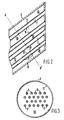
- the bottom part of the fluid catalytic cracking riser reactor as depicted in Figure 1 comprises a substantially vertically vessel (1) provided with an inlet means (2) for introducing catalyst particles, and four devices (3) (of which only two have been shown) for introducing hydrocarbon oil into the riser reactor.
- the riser reactor furthermore preferably comprises fluidization means (4), for instance in the form of a ring-shaped or annular fluidization means, provided with regularly spaced fluidization gas openings (e.g. nozzles (5)) through which a fluidization gas, for instance steam, introduced via fluidization gas inlet means (6) emanates into the bottom section (12) of the reactor.
- the device (3) comprises tubular supply means (7) having openings (8) in their walls (9), and a space (10) arranged between the tubular supply means (7) and wall (11) of the device (3).
- a stream of catalyst particles in a carrier gas (e.g. originating from a catalyst regenerator) is introduced through inlet means (2) into the bottom section (12) of the riser reactor.
- the catalyst particles are fluidized and transported upwardly by means of for instance steam introduced via line (6) into ring-shaped or annular fluidization means (4) provided with regularly spaced fluidization nozzles (5).
- a stream of a hydrocarbon oil is introduced into supply means (7) of the device (3) and mixed with a stream of steam which enters from space (10) under pressure with a high velocity the supply means (7).
- the upwardly flowing fluidized mass of catalyst particles is excellently mixed with the mixture of the hydrocarbon oil and steam obtained emanating with a high velocity from device (3).
- the devices (3) are arranged onto the wall of the vessel (1). It will be understood, however, that the device(s) (3) can also suitably be arranged differently, for instance substantially centrally in the bottom section (12) of the riser reactor or at other suitable places in the riser reactor or stripping zone of a catalytic cracking reactor.
- tubular supply means (7) are arranged parallel with respect to each other. It will be clear, however, that the supply means (7) can also suitably arranged in a different manner, for instance the supply means (7) may diverge from each other in the direction of the upstream end of the device (3).
- the mixing of the gas and the hydrocarbon oil in the supply means (7) is preferably carried out at temperatures in the range of 50-600°C, more preferably in the range from 100-400°C.
- the process for the catalytic cracking of a hydrocarbon oil according to the present invention is preferably carried out at a temperature from 400-800°C and pressures from 1-10 bar. It will be understood that the present process can suitably be carried out using any fluidized catalytic cracking catalyst, however, zeolite-containing catalysts are preferred.
- the hydrocarbon oil which can suitably be converted in the process according to the present invention comprises heavy hydrocarbon oils, for instance atmospheric or vacuum distillates, cycle oils and slurry oils, deasphalted oils, atmospheric and vacuum residues, thermally cracked residues, asphalts originating from various kinds of deasphalting processes, synthetic residues and hydrocarbon oils originating from hydroconversion processes, tar sands and shale oils of any source, and/or any mixture thereof.
- heavy hydrocarbon oils for instance atmospheric or vacuum distillates, cycle oils and slurry oils, deasphalted oils, atmospheric and vacuum residues, thermally cracked residues, asphalts originating from various kinds of deasphalting processes, synthetic residues and hydrocarbon oils originating from hydroconversion processes, tar sands and shale oils of any source, and/or any mixture thereof.
- the present invention is illustrated by means of the following Example.
- a feed stream of a straight run heavy hydrocarbon oil enters supply means (7) of the riser reactor as partly depicted in Figure 1 at a temperature of 260°C and is mixed in the supply means (7) with a stream of steam, which enters space (10) at a temperature of 260°C and a pressure of 6 bar.
- the resulting oil/steam mixture flows with a velocity of more than 70 m/s through the upstream end of supply means (7) into the reactor vessel (1), which is operated at a pressure of 3 bar and a temperature of 520°C.
- Regenerated zeolite Y based catalyst particles are introduced via inlet (2) at a temperature of 705°C into the reactor vessel (1) wherein the catalyst particles are contacted with the oil/steam mixture.
Landscapes
- Chemical & Material Sciences (AREA)
- Oil, Petroleum & Natural Gas (AREA)
- Organic Chemistry (AREA)
- Chemical Kinetics & Catalysis (AREA)
- Engineering & Computer Science (AREA)
- General Chemical & Material Sciences (AREA)
- Combustion & Propulsion (AREA)
- Production Of Liquid Hydrocarbon Mixture For Refining Petroleum (AREA)
- Devices And Processes Conducted In The Presence Of Fluids And Solid Particles (AREA)
Priority Applications (1)
| Application Number | Priority Date | Filing Date | Title |
|---|---|---|---|
| AT90202703T ATE101872T1 (de) | 1989-10-17 | 1990-10-11 | Verfahren zum katalytischen kracken eines kohlenwasserstoffoels. |
Applications Claiming Priority (2)
| Application Number | Priority Date | Filing Date | Title |
|---|---|---|---|
| GB898923345A GB8923345D0 (en) | 1989-10-17 | 1989-10-17 | Process for the catalytic cracking of a hydrocarbon oil |
| GB8923345 | 1989-10-17 |
Publications (2)
| Publication Number | Publication Date |
|---|---|
| EP0423876A1 true EP0423876A1 (de) | 1991-04-24 |
| EP0423876B1 EP0423876B1 (de) | 1994-02-23 |
Family
ID=10664693
Family Applications (1)
| Application Number | Title | Priority Date | Filing Date |
|---|---|---|---|
| EP90202703A Expired - Lifetime EP0423876B1 (de) | 1989-10-17 | 1990-10-11 | Verfahren zum katalytischen Kracken eines Kohlenwasserstofföls |
Country Status (16)
| Country | Link |
|---|---|
| EP (1) | EP0423876B1 (de) |
| JP (1) | JP2841118B2 (de) |
| KR (1) | KR0162494B1 (de) |
| CN (1) | CN1024133C (de) |
| AR (1) | AR248042A1 (de) |
| AT (1) | ATE101872T1 (de) |
| AU (1) | AU637148B2 (de) |
| BR (1) | BR9005171A (de) |
| CA (1) | CA2027688C (de) |
| DE (1) | DE69006815T2 (de) |
| ES (1) | ES2050940T3 (de) |
| GB (1) | GB8923345D0 (de) |
| MY (1) | MY106835A (de) |
| RU (1) | RU2002795C1 (de) |
| TW (1) | TW283165B (de) |
| ZA (1) | ZA908225B (de) |
Cited By (3)
| Publication number | Priority date | Publication date | Assignee | Title |
|---|---|---|---|---|
| EP0458416A1 (de) * | 1990-05-22 | 1991-11-27 | Shell Internationale Researchmaatschappij B.V. | Einrichtung und Verfahren zum Einführen von Katalysatorteilchen in ein bewegliches Bett |
| US5794857A (en) * | 1995-03-07 | 1998-08-18 | Shell Oil Company | Feed nozzle |
| EP1954356A4 (de) * | 2005-11-29 | 2017-12-13 | Bete Fog Nozzle, Inc. | Sprühdüsen |
Families Citing this family (1)
| Publication number | Priority date | Publication date | Assignee | Title |
|---|---|---|---|---|
| US20190380257A1 (en) * | 2018-06-19 | 2019-12-19 | Kuraray Co., Ltd. | Aqueous seed coating composition |
Citations (3)
| Publication number | Priority date | Publication date | Assignee | Title |
|---|---|---|---|---|
| US3812029A (en) * | 1972-10-13 | 1974-05-21 | Mobil Oil Corp | Device for injecting easily coked fluids into a high temperature vessel |
| EP0239171A2 (de) * | 1986-03-27 | 1987-09-30 | Shell Internationale Researchmaatschappij B.V. | Apparat und Verfahren zum Mischen von Flüssigkeiten |
| EP0318185A1 (de) * | 1987-11-23 | 1989-05-31 | Conoco Inc. | Anordnung für FCC-Einsatzdüsen |
-
1989
- 1989-10-17 GB GB898923345A patent/GB8923345D0/en active Pending
-
1990
- 1990-09-26 TW TW079108097A patent/TW283165B/zh active
- 1990-10-11 DE DE69006815T patent/DE69006815T2/de not_active Expired - Fee Related
- 1990-10-11 EP EP90202703A patent/EP0423876B1/de not_active Expired - Lifetime
- 1990-10-11 ES ES90202703T patent/ES2050940T3/es not_active Expired - Lifetime
- 1990-10-11 AT AT90202703T patent/ATE101872T1/de not_active IP Right Cessation
- 1990-10-12 AR AR90318073A patent/AR248042A1/es active
- 1990-10-15 AU AU64628/90A patent/AU637148B2/en not_active Ceased
- 1990-10-15 ZA ZA908225A patent/ZA908225B/xx unknown
- 1990-10-15 RU SU904831462A patent/RU2002795C1/ru active
- 1990-10-15 JP JP2273491A patent/JP2841118B2/ja not_active Expired - Fee Related
- 1990-10-15 MY MYPI90001786A patent/MY106835A/en unknown
- 1990-10-15 KR KR1019900016385A patent/KR0162494B1/ko not_active Expired - Fee Related
- 1990-10-15 BR BR909005171A patent/BR9005171A/pt not_active IP Right Cessation
- 1990-10-15 CN CN90108437A patent/CN1024133C/zh not_active Expired - Fee Related
- 1990-10-15 CA CA002027688A patent/CA2027688C/en not_active Expired - Fee Related
Patent Citations (3)
| Publication number | Priority date | Publication date | Assignee | Title |
|---|---|---|---|---|
| US3812029A (en) * | 1972-10-13 | 1974-05-21 | Mobil Oil Corp | Device for injecting easily coked fluids into a high temperature vessel |
| EP0239171A2 (de) * | 1986-03-27 | 1987-09-30 | Shell Internationale Researchmaatschappij B.V. | Apparat und Verfahren zum Mischen von Flüssigkeiten |
| EP0318185A1 (de) * | 1987-11-23 | 1989-05-31 | Conoco Inc. | Anordnung für FCC-Einsatzdüsen |
Cited By (5)
| Publication number | Priority date | Publication date | Assignee | Title |
|---|---|---|---|---|
| EP0458416A1 (de) * | 1990-05-22 | 1991-11-27 | Shell Internationale Researchmaatschappij B.V. | Einrichtung und Verfahren zum Einführen von Katalysatorteilchen in ein bewegliches Bett |
| US5205992A (en) * | 1990-05-22 | 1993-04-27 | Shell Oil Company | Apparatus for introducing catalyst particles into a moving bed of catalyst |
| US5794857A (en) * | 1995-03-07 | 1998-08-18 | Shell Oil Company | Feed nozzle |
| US5979799A (en) * | 1995-03-07 | 1999-11-09 | Shell Oil Company | Feed nozzle |
| EP1954356A4 (de) * | 2005-11-29 | 2017-12-13 | Bete Fog Nozzle, Inc. | Sprühdüsen |
Also Published As
| Publication number | Publication date |
|---|---|
| JPH03140395A (ja) | 1991-06-14 |
| ZA908225B (en) | 1991-07-31 |
| ES2050940T3 (es) | 1994-06-01 |
| RU2002795C1 (ru) | 1993-11-15 |
| KR910008111A (ko) | 1991-05-30 |
| BR9005171A (pt) | 1991-09-17 |
| AR248042A1 (es) | 1995-05-31 |
| AU6462890A (en) | 1991-04-26 |
| CN1024133C (zh) | 1994-04-06 |
| JP2841118B2 (ja) | 1998-12-24 |
| ATE101872T1 (de) | 1994-03-15 |
| AU637148B2 (en) | 1993-05-20 |
| CN1051053A (zh) | 1991-05-01 |
| TW283165B (de) | 1996-08-11 |
| DE69006815T2 (de) | 1994-06-01 |
| EP0423876B1 (de) | 1994-02-23 |
| DE69006815D1 (de) | 1994-03-31 |
| KR0162494B1 (ko) | 1999-01-15 |
| GB8923345D0 (en) | 1989-12-06 |
| MY106835A (en) | 1995-07-31 |
| CA2027688A1 (en) | 1991-04-18 |
| CA2027688C (en) | 2003-09-30 |
Similar Documents
| Publication | Publication Date | Title |
|---|---|---|
| US7261807B2 (en) | Fluid cat cracking with high olefins production | |
| EP0106052B1 (de) | Entmetallisierung und Entkarbonisierung schwerer Rückstandsöl-Einsatzprodukte | |
| US5154818A (en) | Multiple zone catalytic cracking of hydrocarbons | |
| US3894933A (en) | Method for producing light fuel oil | |
| US4057397A (en) | System for regenerating fluidizable catalyst particles | |
| US3812029A (en) | Device for injecting easily coked fluids into a high temperature vessel | |
| US20100080741A1 (en) | Apparatus for Mixing Regenerated and Carbonized Catalyst | |
| CN109705905B (zh) | 一种多产低碳烯烃的方法和装置 | |
| CN109704904B (zh) | 一种多产低碳烯烃和轻芳烃的方法 | |
| US3904548A (en) | Regenerating catalyst with tangential introduction and circumferential swirl in a fluidized bed | |
| EP0458416B1 (de) | Einrichtung und Verfahren zum Einführen von Katalysatorteilchen in ein bewegliches Bett | |
| JPH0623301A (ja) | ライザ・サイクロン分離器 | |
| US4036779A (en) | Method of regenerating catalyst in a swirl type regenerator containing a dilute phase baffle | |
| JP2018534395A (ja) | 流動接触分解のための方法およびシステム | |
| US3926843A (en) | Fcc ' 'multi-stage regeneration procedure | |
| JP2012504172A (ja) | 再生した触媒及び炭化した触媒を混合するための装置及び方法 | |
| CA1055915A (en) | Method and system for regenerating fluidizable catalyst particles | |
| US3894936A (en) | Conversion of hydrocarbons with {37 Y{38 {0 faujasite-type catalysts | |
| US2883332A (en) | Conversion process and apparatus with plural stages and intermediate stripping zone | |
| EP0593823B1 (de) | Trennung und Abschreckung eines Abflusses einem FCC-Steigrohr | |
| CA2027688C (en) | Process for the catalytic cracking of a hydrocarbon oil | |
| US3791962A (en) | Selective catalytic cracking with crystalline zeolites | |
| CN109678634B (zh) | 一种多产乙烯和丙烯的催化裂化方法 | |
| US5160706A (en) | Process for the catalytic cracking of a hydrocarbon oil | |
| EP0063901A1 (de) | Katalytisches Wirbelschichtverfahren und Vorrichtung |
Legal Events
| Date | Code | Title | Description |
|---|---|---|---|
| PUAI | Public reference made under article 153(3) epc to a published international application that has entered the european phase |
Free format text: ORIGINAL CODE: 0009012 |
|
| AK | Designated contracting states |
Kind code of ref document: A1 Designated state(s): AT BE CH DE ES FR GB IT LI NL SE |
|
| 17P | Request for examination filed |
Effective date: 19910910 |
|
| 17Q | First examination report despatched |
Effective date: 19920914 |
|
| GRAA | (expected) grant |
Free format text: ORIGINAL CODE: 0009210 |
|
| AK | Designated contracting states |
Kind code of ref document: B1 Designated state(s): AT BE CH DE ES FR GB IT LI NL SE |
|
| REF | Corresponds to: |
Ref document number: 101872 Country of ref document: AT Date of ref document: 19940315 Kind code of ref document: T |
|
| REF | Corresponds to: |
Ref document number: 69006815 Country of ref document: DE Date of ref document: 19940331 |
|
| ITF | It: translation for a ep patent filed | ||
| ET | Fr: translation filed | ||
| REG | Reference to a national code |
Ref country code: ES Ref legal event code: FG2A Ref document number: 2050940 Country of ref document: ES Kind code of ref document: T3 |
|
| PLBE | No opposition filed within time limit |
Free format text: ORIGINAL CODE: 0009261 |
|
| STAA | Information on the status of an ep patent application or granted ep patent |
Free format text: STATUS: NO OPPOSITION FILED WITHIN TIME LIMIT |
|
| EAL | Se: european patent in force in sweden |
Ref document number: 90202703.6 |
|
| 26N | No opposition filed | ||
| PGFP | Annual fee paid to national office [announced via postgrant information from national office to epo] |
Ref country code: AT Payment date: 19960923 Year of fee payment: 7 |
|
| PGFP | Annual fee paid to national office [announced via postgrant information from national office to epo] |
Ref country code: CH Payment date: 19970103 Year of fee payment: 7 |
|
| PG25 | Lapsed in a contracting state [announced via postgrant information from national office to epo] |
Ref country code: AT Free format text: LAPSE BECAUSE OF NON-PAYMENT OF DUE FEES Effective date: 19971011 |
|
| PG25 | Lapsed in a contracting state [announced via postgrant information from national office to epo] |
Ref country code: CH Free format text: LAPSE BECAUSE OF NON-PAYMENT OF DUE FEES Effective date: 19971031 Ref country code: LI Free format text: LAPSE BECAUSE OF NON-PAYMENT OF DUE FEES Effective date: 19971031 |
|
| REG | Reference to a national code |
Ref country code: CH Ref legal event code: PL |
|
| PGFP | Annual fee paid to national office [announced via postgrant information from national office to epo] |
Ref country code: SE Payment date: 19990901 Year of fee payment: 10 |
|
| PGFP | Annual fee paid to national office [announced via postgrant information from national office to epo] |
Ref country code: BE Payment date: 19991005 Year of fee payment: 10 |
|
| PGFP | Annual fee paid to national office [announced via postgrant information from national office to epo] |
Ref country code: ES Payment date: 19991020 Year of fee payment: 10 |
|
| PGFP | Annual fee paid to national office [announced via postgrant information from national office to epo] |
Ref country code: NL Payment date: 19991026 Year of fee payment: 10 |
|
| PG25 | Lapsed in a contracting state [announced via postgrant information from national office to epo] |
Ref country code: ES Free format text: LAPSE BECAUSE OF NON-PAYMENT OF DUE FEES Effective date: 20001012 |
|
| PG25 | Lapsed in a contracting state [announced via postgrant information from national office to epo] |
Ref country code: SE Free format text: THE PATENT HAS BEEN ANNULLED BY A DECISION OF A NATIONAL AUTHORITY Effective date: 20001030 |
|
| PG25 | Lapsed in a contracting state [announced via postgrant information from national office to epo] |
Ref country code: BE Free format text: LAPSE BECAUSE OF NON-PAYMENT OF DUE FEES Effective date: 20001031 |
|
| BERE | Be: lapsed |
Owner name: SHELL INTERNATIONALE RESEARCH MAATSCHAPPIJ B.V. Effective date: 20001031 |
|
| PG25 | Lapsed in a contracting state [announced via postgrant information from national office to epo] |
Ref country code: NL Free format text: LAPSE BECAUSE OF NON-PAYMENT OF DUE FEES Effective date: 20010501 |
|
| EUG | Se: european patent has lapsed |
Ref document number: 90202703.6 |
|
| NLV4 | Nl: lapsed or anulled due to non-payment of the annual fee |
Effective date: 20010501 |
|
| REG | Reference to a national code |
Ref country code: GB Ref legal event code: IF02 |
|
| REG | Reference to a national code |
Ref country code: ES Ref legal event code: FD2A Effective date: 20011113 |
|
| PGFP | Annual fee paid to national office [announced via postgrant information from national office to epo] |
Ref country code: GB Payment date: 20070921 Year of fee payment: 18 |
|
| PGFP | Annual fee paid to national office [announced via postgrant information from national office to epo] |
Ref country code: DE Payment date: 20071105 Year of fee payment: 18 |
|
| PGFP | Annual fee paid to national office [announced via postgrant information from national office to epo] |
Ref country code: IT Payment date: 20071025 Year of fee payment: 18 |
|
| PGFP | Annual fee paid to national office [announced via postgrant information from national office to epo] |
Ref country code: FR Payment date: 20070912 Year of fee payment: 18 |
|
| GBPC | Gb: european patent ceased through non-payment of renewal fee |
Effective date: 20081011 |
|
| REG | Reference to a national code |
Ref country code: FR Ref legal event code: ST Effective date: 20090630 |
|
| PG25 | Lapsed in a contracting state [announced via postgrant information from national office to epo] |
Ref country code: IT Free format text: LAPSE BECAUSE OF NON-PAYMENT OF DUE FEES Effective date: 20081011 Ref country code: DE Free format text: LAPSE BECAUSE OF NON-PAYMENT OF DUE FEES Effective date: 20090501 |
|
| PG25 | Lapsed in a contracting state [announced via postgrant information from national office to epo] |
Ref country code: FR Free format text: LAPSE BECAUSE OF NON-PAYMENT OF DUE FEES Effective date: 20081031 |
|
| PG25 | Lapsed in a contracting state [announced via postgrant information from national office to epo] |
Ref country code: GB Free format text: LAPSE BECAUSE OF NON-PAYMENT OF DUE FEES Effective date: 20081011 |