EP0424716A1 - Machine d'impression à tampon avec dispositif de nettoyage du tampon et procédé pour sa mise en oeuvre - Google Patents
Machine d'impression à tampon avec dispositif de nettoyage du tampon et procédé pour sa mise en oeuvre Download PDFInfo
- Publication number
- EP0424716A1 EP0424716A1 EP90119228A EP90119228A EP0424716A1 EP 0424716 A1 EP0424716 A1 EP 0424716A1 EP 90119228 A EP90119228 A EP 90119228A EP 90119228 A EP90119228 A EP 90119228A EP 0424716 A1 EP0424716 A1 EP 0424716A1
- Authority
- EP
- European Patent Office
- Prior art keywords
- cleaning
- printing
- tampon
- pad
- cliché
- Prior art date
- Legal status (The legal status is an assumption and is not a legal conclusion. Google has not performed a legal analysis and makes no representation as to the accuracy of the status listed.)
- Granted
Links
Images
Classifications
-
- B—PERFORMING OPERATIONS; TRANSPORTING
- B41—PRINTING; LINING MACHINES; TYPEWRITERS; STAMPS
- B41F—PRINTING MACHINES OR PRESSES
- B41F17/00—Printing apparatus or machines of special types or for particular purposes, not otherwise provided for
- B41F17/001—Pad printing apparatus or machines
Definitions
- the invention relates to a tampon printing machine with at least one printing cliché, at least one tampon, which is fastened in a printing device and which can be moved by means of the latter in a color recording position against the printing cliché and in a printing position against a workpiece to be printed, and with a cleaning device for the tampon. which forms a cleaning surface on which the tampon can be applied for cleaning.
- the invention further relates to a method for operating such a machine.
- Pad printing machines and the corresponding printing principle have been known for a long time, for which purpose e.g. can be referred to US-PS 463 655.
- a tampon i.e. an elastic ink transfer body, is lowered onto a previously colored printing plate. The ink reaches the tampon and is then transferred to a workpiece by means of this.
- the entire printing ink gets from the tampon to the workpiece during the printing process, so that there is no more ink on the tampon after the printing process.
- ink residues accumulate on the tampon after a number of printing processes, which necessitate periodic cleaning of the tampon.
- contaminating exudation of silicone oil from the tampon rubber can take place.
- Periodic cleaning when the print quality deteriorates is usually carried out manually by an operator. This requires monitoring the printing press during the entire operating time. A manual cleaning process also causes an interruption in operation with a corresponding reduction in emissions. Furthermore, the tampon can easily be damaged. After all, cleaning is often only carried out after rejects with poor printing have already been produced.
- Pad printing machines have become known, in particular for multi-color printing, in which, in order to prevent color mixing, the pad is moved to a specially provided cleaning point before each printing operation or before each color change and is printed there on a blotting paper surface.
- the construction of this machine is complex and the cleaning cycle takes a relatively long time, so that such a system cannot be used economically, in particular for single-color printing.
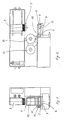
- the machine has a printing device 1 to which a tampon 2 can be attached (only shown in FIG. 3).
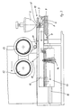
- the printing device 1 can be moved on a carriage 3 between an ink recording position (FIG. 2) and a printing position (cf. dashed line in FIG. 5).
- the ink recording position the printing device 1 is located above a cliché carrier 4.
- the tampon can be used for ink recording with the aid of a drive, e.g. a lifting cylinder can be pneumatically lowered onto the cliché located on the cliché carrier 4.
- the inked tampon is located over a workpiece and can then be lowered onto it in order to transfer the printed image.
- the cliché Before each color recording, the cliché is provided with printing ink by means of a coloring device 5. For this purpose, it is moved from a retracted starting position over the printing cliché to an off position Driving position (Fig. 2) and moved back again, with 8 ink being distributed from a paint tray 7 over the cliché during the forward movement by a spatula and the cliché being doctored off with a squeegee holder with a squeegee 6, so that the printing ink is only removed is present in the recesses of the cliché. So far, the present printing press corresponds to conventional technology.
- the tampon printing machine has a cleaning device 10 for the tampon, which is arranged above the inking device 5.
- the cleaning device 10 essentially has a table 11, over which a cleaning belt 14 can be advanced from a supply roll 12 to a drive-holding take-up roll 13.
- the feed length is adjustable and can therefore be adapted to the tampon size, e.g. to save tape material for small tampon sizes.
- the cleaning tape 14 is preferably a one-sided coated adhesive tape with a width that is greater than the largest possible cliché width that can be processed by the machine.
- suitable absorbent cloth or paper or a statically charged tape or the like can also be used for this.
- the cleaning tape 14 is guided around the table 11 with the adhesive side facing outwards.
- the band 14 on the top of the table thus forms a cleaning surface onto which the tampon can be lowered in its ink receiving position (FIG. 3) when the inking device 5 together with the cleaning device 10 is in the extended position above the cliché carrier 4.
- the table 11 and the tape rolls 12, 13 of the cleaning device are arranged on a U-shaped support part 15 (cf. FIG. 1) which overlaps the inking device 5 on the side.
- the inking device 5 is located on a carriage 17 which runs along a guide 18 from the starting position into an extension position and can be moved back.
- the cleaning device 10, or its supporting part 15, is coupled to the carriage 17 by means of a spring bolt 16 and moves during operation together with the latter from the initial position into the extended position, as indicated in FIG. 3, and back again.
- the tampon 2 is only lowered onto the cliché carrier 4 when the cliché is colored, i.e. when the coloring device 5, together with the cleaning device 10, has moved back to the starting position and the cliché has been released.
- the inking device 5, together with the cleaning device 10 remains in the extended position after being extended, as shown in FIG. 3.
- the tampon 2 is now lowered onto the table 11 with a smaller stroke instead of the cliché and is cleaned there by pressing onto the belt 14. Thereafter, the tampon 2 is raised again and the cleaning device 10 is withdrawn together with the inking device, the cliché being scraped off at the same time.
- the cleaning belt has been moved so far by means of the take-up roller 13 that the table 11 is provided with a previously unused location on the cleaning belt 14.
- the machine control system is now designed such that a cleaning cycle of the type described is inserted after an adjustable number of printing cycles. As can be seen from the previous description, there are no special measures for this machine movements necessary that are not already carried out otherwise.
- the control is therefore essentially limited to changing the chronological sequence of the individual movements. It is implemented, for example, by means of a microprocessor in which the processes of the printing cycle and cleaning cycle are stored as programs.
- it is advantageous to monitor the duration of each printing cycle between ink recording and printing. If this time becomes too long for any reason, the ink dries on the tampon before it is transferred to the workpiece.
- cleaning of the tampon is indicated before the next printing process.
- the controller or the microprocessor has a time counter that is started when the color is recorded. If the printing process does not take place within a certain, adjustable time window after the ink recording, the printing cycle is interrupted and a cleaning cycle is inserted to remove the dried printing ink from the tampon.
- the table 11 of the cleaning device 10 is in operation above the inking device 5 and is moved back and forth together with it.
- the squeegee holder 6 must be able to be removed in order to refill the printing ink into the ink tray 7 or for cleaning and service purposes.
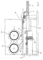
- the table 11 can be moved back together with the carrier 15 with respect to the slide 17 after the spring bolt 16 has been loosened (cf. FIG. 3).
- the squeegee holder 6 In the retracted position of the table 11 (see FIG. 4), the squeegee holder 6 is exposed and can be removed, so that the ink tray 7 is also accessible. If the cleaning function is not required, the machine can also be operated in this state.
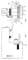
- FIGS. 5 and 6 now show a further embodiment of a tampon printing machine according to the invention, which is particularly suitable for wide or several printing clichés arranged next to one another.
- This machine will not be described in detail, since its basic structure largely corresponds to the first version. The same reference numbers are therefore also used.
- the essential difference is that the tape rolls 12, 13 for the cleaning tape are arranged laterally on the inking device 5 with respect to the direction of displacement.
- the table 11 of the cleaning device thus extends transversely to the machine axis and has at least the width of the cliché carrier or the printing device 1, with which wide printing patterns can be attached in the manner described, ie with periodic tampon cleaning.
- This embodiment shows that the arrangement of the cleaning tape or the tape rolls can largely be adapted to the respective requirements of the pressure. The same naturally applies to the width of the cleaning tape used in each case.
Landscapes
- Inking, Control Or Cleaning Of Printing Machines (AREA)
Applications Claiming Priority (2)
| Application Number | Priority Date | Filing Date | Title |
|---|---|---|---|
| CH385989A CH679846A5 (fr) | 1989-10-24 | 1989-10-24 | |
| CH3859/89 | 1989-10-24 |
Publications (2)
| Publication Number | Publication Date |
|---|---|
| EP0424716A1 true EP0424716A1 (fr) | 1991-05-02 |
| EP0424716B1 EP0424716B1 (fr) | 1995-01-04 |
Family
ID=4265003
Family Applications (1)
| Application Number | Title | Priority Date | Filing Date |
|---|---|---|---|
| EP19900119228 Revoked EP0424716B1 (fr) | 1989-10-24 | 1990-10-06 | Machine d'impression à tampon avec dispositif de nettoyage du tampon et procédé pour sa mise en oeuvre |
Country Status (3)
| Country | Link |
|---|---|
| EP (1) | EP0424716B1 (fr) |
| CH (1) | CH679846A5 (fr) |
| DE (1) | DE59008188D1 (fr) |
Cited By (8)
| Publication number | Priority date | Publication date | Assignee | Title |
|---|---|---|---|---|
| EP0826496A3 (fr) * | 1996-08-30 | 1998-09-02 | Tampoprint GmbH | Dispositif de nettoyage dans une machine d'impression au tampon |
| US6123021A (en) * | 1998-12-09 | 2000-09-26 | Cameron; Robert | Multiple color printer for printing on small objects |
| EP1177894A1 (fr) * | 2000-08-04 | 2002-02-06 | Tampoprint GmbH | Machine d'impression au tampon |
| US6393981B1 (en) | 1998-12-09 | 2002-05-28 | Robert Cameron | Multiple color printer having vertically moveable print pad |
| CN104441946A (zh) * | 2013-09-20 | 2015-03-25 | 天津中电华利电器科技集团有限公司 | 一种微型断路器移印设备 |
| CN104890356A (zh) * | 2014-03-03 | 2015-09-09 | 温州奔龙自动化科技有限公司 | 一种漏电断路器四色移印装置 |
| CN107379744A (zh) * | 2017-07-20 | 2017-11-24 | 苏州市烨铭塑胶制品厂 | 一种红外线移印机胶头 |
| CN110539553A (zh) * | 2019-09-24 | 2019-12-06 | 东莞广华汽车饰件科技有限公司 | 一种充气式移印装置 |
Families Citing this family (2)
| Publication number | Priority date | Publication date | Assignee | Title |
|---|---|---|---|---|
| DE19921702A1 (de) * | 1999-05-12 | 2000-11-23 | Braun Gmbh | Verfahren zum Betreiben einer Tampondruckvorrichtung sowie Tampondruckvorrichtung |
| CN108202528A (zh) * | 2016-12-19 | 2018-06-26 | 汉达精密电子(昆山)有限公司 | 自动清洁胶头结构 |
Citations (3)
| Publication number | Priority date | Publication date | Assignee | Title |
|---|---|---|---|---|
| DE8528619U1 (de) * | 1985-10-08 | 1985-12-19 | TAMPOflex GmbH, 7257 Ditzingen | Tampondruckmaschine |
| DE8704867U1 (de) * | 1987-04-01 | 1987-05-21 | Morlock Mechanik GmbH, 7292 Baiersbronn | Tampondruckmaschine |
| DE3608125A1 (de) * | 1986-03-05 | 1987-09-10 | Tampoflex Gmbh | Verfahren fuer den tampondruck |
-
1989
- 1989-10-24 CH CH385989A patent/CH679846A5/de not_active IP Right Cessation
-
1990
- 1990-10-06 DE DE59008188T patent/DE59008188D1/de not_active Revoked
- 1990-10-06 EP EP19900119228 patent/EP0424716B1/fr not_active Revoked
Patent Citations (3)
| Publication number | Priority date | Publication date | Assignee | Title |
|---|---|---|---|---|
| DE8528619U1 (de) * | 1985-10-08 | 1985-12-19 | TAMPOflex GmbH, 7257 Ditzingen | Tampondruckmaschine |
| DE3608125A1 (de) * | 1986-03-05 | 1987-09-10 | Tampoflex Gmbh | Verfahren fuer den tampondruck |
| DE8704867U1 (de) * | 1987-04-01 | 1987-05-21 | Morlock Mechanik GmbH, 7292 Baiersbronn | Tampondruckmaschine |
Cited By (11)
| Publication number | Priority date | Publication date | Assignee | Title |
|---|---|---|---|---|
| EP0826496A3 (fr) * | 1996-08-30 | 1998-09-02 | Tampoprint GmbH | Dispositif de nettoyage dans une machine d'impression au tampon |
| US6123021A (en) * | 1998-12-09 | 2000-09-26 | Cameron; Robert | Multiple color printer for printing on small objects |
| US6393981B1 (en) | 1998-12-09 | 2002-05-28 | Robert Cameron | Multiple color printer having vertically moveable print pad |
| EP1177894A1 (fr) * | 2000-08-04 | 2002-02-06 | Tampoprint GmbH | Machine d'impression au tampon |
| DE10038166A1 (de) * | 2000-08-04 | 2002-02-14 | Tampoprint Gmbh | Tampondruckmaschine |
| DE10038166C2 (de) * | 2000-08-04 | 2003-08-21 | Tampoprint Gmbh | Tampondruckmaschine |
| CN104441946A (zh) * | 2013-09-20 | 2015-03-25 | 天津中电华利电器科技集团有限公司 | 一种微型断路器移印设备 |
| CN104890356A (zh) * | 2014-03-03 | 2015-09-09 | 温州奔龙自动化科技有限公司 | 一种漏电断路器四色移印装置 |
| CN104890356B (zh) * | 2014-03-03 | 2019-09-03 | 奔龙自动化科技有限公司 | 一种漏电断路器四色移印装置 |
| CN107379744A (zh) * | 2017-07-20 | 2017-11-24 | 苏州市烨铭塑胶制品厂 | 一种红外线移印机胶头 |
| CN110539553A (zh) * | 2019-09-24 | 2019-12-06 | 东莞广华汽车饰件科技有限公司 | 一种充气式移印装置 |
Also Published As
| Publication number | Publication date |
|---|---|
| DE59008188D1 (de) | 1995-02-16 |
| CH679846A5 (fr) | 1992-04-30 |
| EP0424716B1 (fr) | 1995-01-04 |
Similar Documents
| Publication | Publication Date | Title |
|---|---|---|
| DE69826545T2 (de) | Druckmaschine mit auswechselbarer Vorrichtung zum Aufbringen von Farbe | |
| CH647718A5 (de) | Vorrichtung zum waschen von zylindern in druckmaschinen. | |
| EP2628594B1 (fr) | Procédé d'impression digitale par tampographie | |
| DE68914934T2 (de) | Reinigungssystem für Bogenoffsetdruckmaschinen. | |
| DE102008053118A1 (de) | Vorrichtung und Verfahren zur Reinigung von Gummitüchern auf Gummituchzylindern | |
| DE4209642A1 (de) | Vorrichtung zur wahlweisen Reinigung mehrerer Zylinder | |
| EP1338418B1 (fr) | Machine à imprimer avec un dispositif de nettoyage du cliché | |
| DE10209091A1 (de) | Vorrichtung zur Reinigung wenigstens eines ausgewählten Abschnittes einer Zylinderoberfläche | |
| EP0424716B1 (fr) | Machine d'impression à tampon avec dispositif de nettoyage du tampon et procédé pour sa mise en oeuvre | |
| EP0351562B1 (fr) | Dispositif de nettoyage d'un cylindre de plaque et d'un cylindre de blanchet d'une machine à imprimer en offset | |
| DE3713433C2 (fr) | ||
| EP0135618A2 (fr) | Machine de sérigraphie | |
| DE68901977T2 (de) | Vorrichtung zum reinigen des gummituches einer druckerpresse. | |
| DE4440325C1 (de) | Reinigungseinrichtung für eine Bogenleiteinrichtung einer Rotationsdruckmaschine | |
| DE4204472C2 (de) | Walzenwechselvorrichtung | |
| DE3025546A1 (de) | Vorrichtung zum aufbringen eines fluessigen bzw. halbfluessigen mediums auf die druckplatte einer druckmaschine, insbesondere offsetdruckmaschine | |
| DE69712571T2 (de) | Verfahren zum Reinigen eines Gummituchzylinders in einer Druckmachine | |
| DE4127682A1 (de) | Verfahren und vorrichtung fuer einen mehrschichten-siebdruck | |
| EP0548501B1 (fr) | Dispositif pour le nettoyage d'un cylindre d'impression flexographique | |
| DE10112756A1 (de) | Filmfarbwerk in einer Druckmaschine und verfahren zu dessen Reinigung | |
| EP1106353B1 (fr) | Procédé et dispositif pour le dépoussiérage d'un support d'impression | |
| DE10038166C2 (de) | Tampondruckmaschine | |
| EP1215046A1 (fr) | Machine à imprimer avec un dispositif de nettoyage du cliché | |
| DE19940533A1 (de) | Reinigungsverfahren zur Reinigung von Druckmaschinenzylindern und Druckmaschine, insbesondere zur Durchführung des Reinigungsverfahrens | |
| DE10157501A1 (de) | Sprühvorrichtung in einer Druckmaschine |
Legal Events
| Date | Code | Title | Description |
|---|---|---|---|
| PUAI | Public reference made under article 153(3) epc to a published international application that has entered the european phase |
Free format text: ORIGINAL CODE: 0009012 |
|
| AK | Designated contracting states |
Kind code of ref document: A1 Designated state(s): BE CH DE FR GB IT LI |
|
| 17P | Request for examination filed |
Effective date: 19911030 |
|
| 17Q | First examination report despatched |
Effective date: 19930721 |
|
| GRAA | (expected) grant |
Free format text: ORIGINAL CODE: 0009210 |
|
| AK | Designated contracting states |
Kind code of ref document: B1 Designated state(s): BE CH DE FR GB IT LI |
|
| ITF | It: translation for a ep patent filed | ||
| REF | Corresponds to: |
Ref document number: 59008188 Country of ref document: DE Date of ref document: 19950216 |
|
| GBT | Gb: translation of ep patent filed (gb section 77(6)(a)/1977) |
Effective date: 19950120 |
|
| ET | Fr: translation filed | ||
| PGFP | Annual fee paid to national office [announced via postgrant information from national office to epo] |
Ref country code: CH Payment date: 19950926 Year of fee payment: 6 |
|
| PGFP | Annual fee paid to national office [announced via postgrant information from national office to epo] |
Ref country code: GB Payment date: 19950927 Year of fee payment: 6 |
|
| PLBI | Opposition filed |
Free format text: ORIGINAL CODE: 0009260 |
|
| PGFP | Annual fee paid to national office [announced via postgrant information from national office to epo] |
Ref country code: BE Payment date: 19951011 Year of fee payment: 6 |
|
| PGFP | Annual fee paid to national office [announced via postgrant information from national office to epo] |
Ref country code: FR Payment date: 19951025 Year of fee payment: 6 |
|
| PGFP | Annual fee paid to national office [announced via postgrant information from national office to epo] |
Ref country code: DE Payment date: 19951031 Year of fee payment: 6 |
|
| 26 | Opposition filed |
Opponent name: TECA-PRINT AG Effective date: 19951004 |
|
| PLBF | Reply of patent proprietor to notice(s) of opposition |
Free format text: ORIGINAL CODE: EPIDOS OBSO |
|
| PLBF | Reply of patent proprietor to notice(s) of opposition |
Free format text: ORIGINAL CODE: EPIDOS OBSO |
|
| RDAG | Patent revoked |
Free format text: ORIGINAL CODE: 0009271 |
|
| STAA | Information on the status of an ep patent application or granted ep patent |
Free format text: STATUS: PATENT REVOKED |
|
| REG | Reference to a national code |
Ref country code: CH Ref legal event code: PL |
|
| GBPR | Gb: patent revoked under art. 102 of the ep convention designating the uk as contracting state |
Free format text: 960527 |
|
| 27W | Patent revoked |
Effective date: 19960527 |