EP0425153A2 - Détecteur de synchronisation utilisant les valeurs de la métrique de chemin et de la métrique de branches d'un décodeur de Viterbi - Google Patents
Détecteur de synchronisation utilisant les valeurs de la métrique de chemin et de la métrique de branches d'un décodeur de Viterbi Download PDFInfo
- Publication number
- EP0425153A2 EP0425153A2 EP90311263A EP90311263A EP0425153A2 EP 0425153 A2 EP0425153 A2 EP 0425153A2 EP 90311263 A EP90311263 A EP 90311263A EP 90311263 A EP90311263 A EP 90311263A EP 0425153 A2 EP0425153 A2 EP 0425153A2
- Authority
- EP
- European Patent Office
- Prior art keywords
- value
- synchronization
- threshold
- indicator
- differences
- Prior art date
- Legal status (The legal status is an assumption and is not a legal conclusion. Google has not performed a legal analysis and makes no representation as to the accuracy of the status listed.)
- Ceased
Links
Images



Classifications
-
- H—ELECTRICITY
- H04—ELECTRIC COMMUNICATION TECHNIQUE
- H04L—TRANSMISSION OF DIGITAL INFORMATION, e.g. TELEGRAPHIC COMMUNICATION
- H04L9/00—Cryptographic mechanisms or cryptographic arrangements for secret or secure communications; Network security protocols
- H04L9/12—Transmitting and receiving encryption devices synchronised or initially set up in a particular manner
-
- H—ELECTRICITY
- H03—ELECTRONIC CIRCUITRY
- H03M—CODING; DECODING; CODE CONVERSION IN GENERAL
- H03M13/00—Coding, decoding or code conversion, for error detection or error correction; Coding theory basic assumptions; Coding bounds; Error probability evaluation methods; Channel models; Simulation or testing of codes
- H03M13/33—Synchronisation based on error coding or decoding
Definitions
- the invention relates to detection of synchronization or lack of synchronization in Viterbi decoders.
- Convolutional codes are widely used for error correction purposes in communications systems. While convolutional coding is used to a large extent in satellite communications, it is also used in a variety of other communication fields. Basically a convolutional code adds redundancy to the information to be transmitted so that, using the redundant information at the receiver, there is the capability of correcting errors occurring by reason of noise and other impairments in the transmission process. While there are many techniques for decoding convolutional codes, an optimal decoder is known as the Viterbi decoder. See for example Forney, “The Viterbi Algorithm", Proceedings of the IEEE , Vol. 61, pp. 268-278, March 1973 and Heller, "Viterbi Decoding for Satellite and Space Communication", IEEE Transactions on Communication Technology , Vol. COM-19, pp. 835-848, October 1971.
- Viterbi decoders Synchronization in Viterbi decoders is addressed by Yasuda Patents 4,527,279 and 4,578,800; Wei Patent 4,641,327 and Gordon Patent 4,675,871. Other aspects of Viterbi decoders are addressed in Acampora Patent 4,087,787; Shenoy Patent 4,583,078; Otani Patent 4,606,027; Martinez Patent 4,709,377; Heichler Patent 4,757,506 and Yamashita Patent 4,777,636.
- the number of symbols in any group of symbols which produce the branch metrics and path metrics depends on the parameters of the code being employed. In a so-called rate one-half code, there are two symbols per group; in a rate three-fourths code, there are four symbols per group; etc.
- the synchronization technique described by Wei selects the minimum branch metric and the minimum (prior to normalization) path metric and uses these values to detect loss of synchronization.
- loss of synchronization When loss of synchronization is detected the receiver is informed to slip (either backward or forward) in order to search for the beginning of the frame.
- the search In rate one-half codes, the search is relatively simple since if the receiver was out-of-sync, a 1-bit shift should produce synchronization. In other codes the search may be more extended.
- the technique which Wei uses employing the minimum branch metric and the (un-normalized) minimum path metric begins by determining the difference between the minimum branch metric and path metric.
- the difference is input to a counter.
- the counter is used to count the rate of occurrences of non-zero differences. If the rate of non-zero occurrences exceeds a threshold, then in the technique described by Wei, an out-of-synchronization condition is declared.
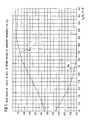
- FIG. 1 plots, for a rate one-half convolutional code of generator polynomials (171, 133), and employing the Wei technique, the rate of non-zero differences vs. signal energy per bit/noise power spectral density ratio (E b /N o ) for both in-synch and out-of-synch conditions.
- E b /N o signal energy per bit/noise power spectral density ratio
- Fig. 1 makes it apparent that there is no fixed threshold which can be used to differentiate the in-synchronization condition from the out-of-synchronization condition. This is for the reason that the rate of non-zero differences for low E b /N o when the decoder is in synchronization overlaps the rate of non-zero differences for high E b /N o when the decoder is out of synchronization.
- the invention provides for reliably detecting the synchronization status of a Viterbi decoder by using a sequence of differences between the minimum branch metric and the corresponding minimum (un-normalized) path metric.
- Any difference value is non-linearly mapped.
- a difference value of zero is mapped into a mapped value of magnitude unity and negative sign.
- Any other difference value is mapped into the corresponding value.
- a difference value of 2 corresponds to a mapped value of 2
- difference value of 5 corresponds to a mapped value of 5, etc. From the sequence of differences a sequence of mapped values is produced.
- An accumulator, counter, indicator or the like is initialized to an initial value and every mapped value of the sequence is summed with the accumulator or counter.
- the first time the accumulator or counter is referred to after initialization to the initial value, the first mapped value is added (algebraically) to produce a sum.
- the next mapped value is also added (algebraically) to the sum to create an updated sum, and so on. Every sum is then compared to two different thresholds.
- the initial value, the value to which the counter or accumulator is initialized, is selected to lie between the two thresholds. If at any time the sum (the value of the counter or accumulator or indicator) reaches or exceeds a first threshold, an out-of-synchronization condition is declared.
- This out-of-synchronization declaration has two effects. In the first place, it is used at the receiver to initiate a search for synchronization by shifting the receiver's previous estimate of the frame termination. The out-of-synchronization declaration is also used to reset the sum (the quantity in the counter or accumulator or indicator) back to the initial value.
- an in-synchronization condition is declared.
- the sum (the value in the counter or accumulator or indicator) is clamped to the second threshold. In other words, the sum is not allowed to decrease in magnitude below the second threshold.
- the invention provides, in a Viterbi decoder, a method of detecting synchronization status using a sequence of differences between minimum path metrics and corresponding minimum branch metrics, said method comprising the steps of:
- the invention provides, in a Viterbi decoder, a method of detecting synchronization status using a sequence of differences between minimum path metrics and corresponding minimum branch metrics, said method comprising the steps of:
- the invention provides, in a Viterbi decoder, a method of detecting synchronization status using a sequence of differences between minimum path metrics and corresponding minimum branch metrics, said method comprising the steps of:
- Fig. 2 shows, in block diagram form, the synchronization method and apparatus of the present invention.
- information is provided to the synchronization apparatus from the Viterbi decoder.
- This information includes, on path 11, a sequence of sets of path metrics (PM i (t)), where i, for every frame, can vary from 0 to P-1.
- PM i (t) path metrics
- BM i (t) branch metrics
- the element 1 determines the minimum path metric PM min (t).
- Element 2 finds, from each set of branch metrics, the minimum branch metric BM min (t).
- the summing device 3 produces the difference ⁇ (t).
- the differences produced by the summing device 3 are input in the same sequence as they are produced, to the non-linear mapping element 4.
- the non-linear mapping element 4 separates zero and non-zero differences. Zero differences are mapped into a first set with one sign (and one mapped value in the set). Non-zero differences are mapped into a second set all with signs different from the one sign. The second set has mapped values equal in magnitude to the non-zero difference.
- the output of the non-linear mapping element is the mapped value corresponding to the difference ⁇ (t), f( ⁇ (t)). The mapped value is output from the non-linear mapping element 4 to an accumulator or summing device 5.
- the summing device or accumulator 5 For each mapped value provided by the non-linear mapping element, the summing device or accumulator 5 produces a sum S d .
- the sum S d is input to the decision element 6.
- the other inputs to the decision element comprise the first and second thresholds TH out and TH in .
- the decision device 6 compares the sum S d to the thresholds. If the sum S d exceeds the threshold TH out , an out-of-synchronization status is declared. The out-of-synchronization status is used to alter the frame/bit sequencing in an attempt to acquire synchronization. Alternatively, if the sum S d is below the second threshold TH in , then an in-synchronization condition is declared.
- a parameter IN-SYNCH reflects the insynchronization or out-of-synchronization status of the decoder.
- the parameter IN-SYNCH is unity and otherwise, when the decoder is out of synchronization (or synchronization has not yet been detected), the parameter IN-SYNCH is zero.
- the third parameter which is employed is the sum S d . In the example shown in Fig. 1, the parameter S d is initialized at zero. As will be described below, this is not essential to the invention.
- the first function F1 is an initialization function, wherein the parameters IN-SYNCH and S d are set to zero, and d is initialized to unity.
- the first step, function F2 is performed when the path metric PM i (d) and branch metric BM i (d) are received.
- function F2 the minimum path metric PM min (d) and the minimum branch metric BM min (d) are determined.
- function F3 determines the difference ⁇ (d).
- function F4 maps the difference. This mapping is non-linear, since depending on the value of ⁇ , it can be mapped into either a first set or a second set of mapped values.
- a mapped value has a sign which is different from the sign of all of the mapped values in the second set.
- the mapped values are input to function F5 which performs the accumulation function.
- S d is computed as S d-1 plus the mapped value from function F4.
- Function F6 then compares the sum S d to determine if it is lower than the in-synch threshold (TH in ). If this criterion is satisfied, then function F8 is performed to change the parameter In-Synch to unity, and at the same time, the sum S d is clamped to the threshold TH in .
- function F6 is performed to see if the sum S d is greater than the threshold TH out . If this criterion is satisfied, then function F9 is performed. In function F9, the parameter In-Synch is set to zero and the sum S d is set to the initialized value. If neither the criterion of functions F6 or F7 is satisfied, then function F10 is performed which merely increments the parameter d, and the next frame is operated on.
- Fig. 4 is a plot of typical values S d as a function of time.
- the threshold TH out and the threshold TH in lie on either side of the initialized value of S d .
- the operation of the functions shown in Fig. 3 is represented in Fig. 4 by showing that the value S d begins increasing until it reaches the threshold TH out . At that point (function F9), the value S d is re-initialized to zero and the process begins again.
- Fig. 4 shows an instance wherein the value S d again reaches TH out and is again re-initialized. Thereafter, as shown in Fig.
- the value S d reaches the threshold TH in and it is clamped at that point, i.e. it is not allowed to decrease below the threshold TH in .
- the parameter In-Synch is now set to unity, i.e. an in-synchronization condition or status is detected.
- the synchronization detector may detect out-of-synchronization if the value of S d again reaches TH out . If that occurs, the value S d is reinitialized and synch detection continues.
- T in TH in /M in .
- T out TH out /M out .
- Both T in and T out are, for a given decoder, with fixed non-linear mapping and a given convolutional code, determined by the threshold values. As the threshold values decrease or approach each other, the detection time, the time to detect in-synchronization or out-of-synchronization status, is decreased. While this is desirable, another important factor in detection of synchronization is the false alarm rate, i.e. the rate at which the synchronization detector determines an out-of-synchronization status when the decoder is actually synchronized. False alarms can occur at low E b /N o ratio circumstances, and results in a loss of a certain amount of information.
- the false alarm rate should be maintained as low as possible, for example once a day for a typical range of E b /N o .
- the distance between the thresholds TH out and TH in there is a tradeoff between minimizing the time to detect synchronization status and at the same time minimizing the false alarm rates, or at least reducing false alarm rates to practical levels.
- the particular non-linear mapping and the particular threshold values depend on the parameters of the various codes which are employed.
- the branch metrics BM and the path metrics PM are determined using 3-bit soft decision detection as opposed to hard decision detection. Accordingly, every received symbol is reflected as three bits of soft decision data, i.e. it is quantized to one of eight levels ranging from 0 to 7.
- ⁇ (t) can be any non-negative integer less than or equal to 7, i.e. lying between 0 and 7.
- the minimum path metric value PM min (t) also takes non-negative integers lying between 0 and 7.
- the branch metric value BM min (t) can be any non-negative integer less than or equal to 6, i.e. lying between 0 and 6.
- non-linear mapping of ⁇ (t) is required, i.e. ⁇ (t) ⁇ f( ⁇ (t)).
- ⁇ (t) ⁇ f( ⁇ (t) To find optimal non-linear mapping is difficult.
- using the occurrence rate of ⁇ (t) sub-optimal non-linear mapping can be determined.
- non-linear mapping of ⁇ (t) is determined as:
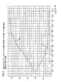
- Fig. 5 shows the mean values M in and M out determined by the simulation.
- An advantage of the non-linear mapping is readily evident from Fig. 5, i.e. the slope of M out is at all times positive whereas, referring to Fig. 1, it can be seen that the problem with the prior art synchronization detection technique is that the slope of the relationship between S d , plotted as a function of E b /N o , becomes negative above 6.0 dB and significantly negative above 8.0 dB.
- the mean values M in and M out increase, the detection times T in and T out become short.
- the distance between TH in and TH out is determined as 127. Determining that the decoder is in synchronization is more important than determining that the decoder is out of synchronization, and so we select a magnitude of the in-synchronization detection value TH in as further from the initial value of S d than is the out-of-synchronization detection value TH out .
- the false alarm rate can be estimated from the maximum value of S d - TH in after S d attains the threshold value TH in for the first time.
- Fig. 6 shows the results of computer simulations using the foregoing non-linear mappings to plot M in and M out vs. E b /N o .
- Fig. 6 shows that the slope of M out remains positive, thus avoiding the problems which are evident in the prior art synchronization detection technique.
- the non-linear mapping is different from the rate 1/2 case in that if the difference between the path metric and branch metric is zero, the non-linear mapped value is -1/16 and if the difference is non-zero, the non-linear mapped value is equal to the difference.
- Fig. 7 plots M in and M out vs. E b /N o . Just as was the case with Figs. 5 and 6, even at high E b /N o , M out remains positive.
Landscapes
- Engineering & Computer Science (AREA)
- Physics & Mathematics (AREA)
- Probability & Statistics with Applications (AREA)
- Theoretical Computer Science (AREA)
- Computer Security & Cryptography (AREA)
- Computer Networks & Wireless Communication (AREA)
- Signal Processing (AREA)
- Error Detection And Correction (AREA)
- Synchronisation In Digital Transmission Systems (AREA)
Applications Claiming Priority (2)
| Application Number | Priority Date | Filing Date | Title |
|---|---|---|---|
| US07/427,167 US5050191A (en) | 1989-10-24 | 1989-10-24 | Synchronization detector using path metric and branch metric values of a Viterbi decoder |
| US427167 | 2003-04-30 |
Publications (2)
| Publication Number | Publication Date |
|---|---|
| EP0425153A2 true EP0425153A2 (fr) | 1991-05-02 |
| EP0425153A3 EP0425153A3 (en) | 1991-09-18 |
Family
ID=23693758
Family Applications (1)
| Application Number | Title | Priority Date | Filing Date |
|---|---|---|---|
| EP19900311263 Ceased EP0425153A3 (en) | 1989-10-24 | 1990-10-15 | Synchronization detector using path metric and branch metric values of a viterbi decoder |
Country Status (5)
| Country | Link |
|---|---|
| US (1) | US5050191A (fr) |
| EP (1) | EP0425153A3 (fr) |
| JP (1) | JP2701972B2 (fr) |
| KR (1) | KR940001758B1 (fr) |
| CA (1) | CA2026021C (fr) |
Cited By (11)
| Publication number | Priority date | Publication date | Assignee | Title |
|---|---|---|---|---|
| EP0543586A3 (fr) * | 1991-11-21 | 1995-05-24 | Sony Corp | |
| EP0631396A3 (fr) * | 1993-06-25 | 1995-11-15 | Oki Electric Ind Co Ltd | Décodeur convolutionnel en temps réel avec fonction de synchronisation de bloc. |
| EP0603824A3 (fr) * | 1992-12-25 | 1995-11-15 | Nec Corp | Méthode et circuit de détection de synchronisation dans un décodeur de viterbi. |
| EP0696108A1 (fr) * | 1994-07-15 | 1996-02-07 | Kabushiki Kaisha Toshiba | Système de transmission et dispositif pour celui-ci |
| FR2725098A1 (fr) * | 1994-09-27 | 1996-03-29 | Alcatel Telspace | Dispositif de synchronisation de branches d'un decodeur de viterbi compris dans un recepteur de donnees numeriques codees en treillis multidimensionnel |
| EP0748057A4 (fr) * | 1993-06-21 | 1997-07-30 | Oki Electric Ind Co Ltd | Methode de comptage des erreurs sur les bits et compteur |
| GB2315000A (en) * | 1996-06-29 | 1998-01-14 | Hyundai Electronics Ind | Detecting sync./async. states of Viterbi decoded data using trace-back |
| SG91299A1 (en) * | 1999-09-03 | 2002-09-17 | Infineon Technologies Corp | Survival selection rule cross-reference to related applications |
| EP1187341A3 (fr) * | 2000-09-06 | 2004-08-25 | Texas Instruments Incorporated | Détection de la perte de synchronisation dans un récepteur V.34 |
| EP0838906A3 (fr) * | 1996-10-25 | 2004-10-13 | Matsushita Electric Industrial Co., Ltd. | Méthode et dispositif pour déterminer des seuils de valeurs métriques utilisés dans des circuits d'évaluateur de synchronisation Viterbi |
| WO2007071192A1 (fr) * | 2005-12-22 | 2007-06-28 | Triductor Technology (Suzhou) Inc. | Decodeur viterbi vdsl2 a pipeline quadrietage |
Families Citing this family (10)
| Publication number | Priority date | Publication date | Assignee | Title |
|---|---|---|---|---|
| JPH0329434A (ja) * | 1989-06-26 | 1991-02-07 | Nec Corp | フレーム同期外れ検出方式 |
| EP0505657A1 (fr) * | 1991-03-27 | 1992-09-30 | International Business Machines Corporation | Reconnaissance de préambule et détection de synchronisation dans des systèmes à résponse partielle |
| US5588028A (en) * | 1993-02-02 | 1996-12-24 | U.S. Robotics | Simplified trellis decoder |
| JP3233485B2 (ja) * | 1993-04-06 | 2001-11-26 | 松下電器産業株式会社 | ディジタル信号検出回路 |
| EP0644661B1 (fr) * | 1993-09-20 | 2000-06-14 | Canon Kabushiki Kaisha | Appareil pour traiter des signaux |
| JP2605641B2 (ja) * | 1994-11-14 | 1997-04-30 | 日本電気株式会社 | 可変ビットレート判別方法及び装置 |
| US5841796A (en) * | 1995-03-14 | 1998-11-24 | Comsat Corporation | Apparatus and method for calculating viterbi path metric using exponentially-weighted moving average |
| US5859861A (en) * | 1995-06-21 | 1999-01-12 | Hyundai Electronics Ind. Co., Ltd. | High speed viterbi decoder |
| US6253347B1 (en) * | 1997-11-05 | 2001-06-26 | Hitachi America, Ltd. | Automatic synchronization circuit for trellis decoder |
| JP4977922B2 (ja) * | 2010-02-25 | 2012-07-18 | 日本電気株式会社 | 同期検出装置、方法及びプログラム |
Family Cites Families (9)
| Publication number | Priority date | Publication date | Assignee | Title |
|---|---|---|---|---|
| JPS5430244B2 (fr) * | 1973-05-17 | 1979-09-29 | ||
| JPS592414B2 (ja) * | 1977-02-12 | 1984-01-18 | 富士通株式会社 | 積分形保護回路 |
| US4527279A (en) * | 1982-07-12 | 1985-07-02 | Kokusai Denshin Denwa Co. | Synchronization circuit for a Viterbi decoder |
| GB8327084D0 (en) * | 1983-10-11 | 1983-11-09 | Gordon J | Error correction decoder apparatus |
| US4601046A (en) * | 1984-05-15 | 1986-07-15 | Halpern Peter H | System for transmitting data through a troposcatter medium |
| US4641327A (en) * | 1985-07-09 | 1987-02-03 | Codex Corporation | Frame synchronization in trellis-coded communication systems |
| JPS62188455A (ja) * | 1986-02-13 | 1987-08-18 | Nec Corp | 誤りパルス発生回路 |
| US4802174A (en) * | 1986-02-19 | 1989-01-31 | Sony Corporation | Viterbi decoder with detection of synchronous or asynchronous states |
| JPS62193323A (ja) * | 1986-02-19 | 1987-08-25 | Sony Corp | ヴイタビ復号装置 |
-
1989
- 1989-10-24 US US07/427,167 patent/US5050191A/en not_active Expired - Lifetime
-
1990
- 1990-09-24 CA CA002026021A patent/CA2026021C/fr not_active Expired - Fee Related
- 1990-10-15 EP EP19900311263 patent/EP0425153A3/en not_active Ceased
- 1990-10-23 KR KR1019900016955A patent/KR940001758B1/ko not_active Expired - Fee Related
- 1990-10-24 JP JP2286949A patent/JP2701972B2/ja not_active Expired - Lifetime
Cited By (18)
| Publication number | Priority date | Publication date | Assignee | Title |
|---|---|---|---|---|
| EP0543586A3 (fr) * | 1991-11-21 | 1995-05-24 | Sony Corp | |
| EP0603824A3 (fr) * | 1992-12-25 | 1995-11-15 | Nec Corp | Méthode et circuit de détection de synchronisation dans un décodeur de viterbi. |
| US5809044A (en) * | 1992-12-25 | 1998-09-15 | Nec Corporation | Method of and circuit for detecting synchronism in viterbi decoder |
| EP0748057A4 (fr) * | 1993-06-21 | 1997-07-30 | Oki Electric Ind Co Ltd | Methode de comptage des erreurs sur les bits et compteur |
| EP0631396A3 (fr) * | 1993-06-25 | 1995-11-15 | Oki Electric Ind Co Ltd | Décodeur convolutionnel en temps réel avec fonction de synchronisation de bloc. |
| EP0696108A1 (fr) * | 1994-07-15 | 1996-02-07 | Kabushiki Kaisha Toshiba | Système de transmission et dispositif pour celui-ci |
| US5757834A (en) * | 1994-09-27 | 1998-05-26 | Alcatel Telspace | Device for synchronizing branches of a Viterbi decoder included in a multidimensional trellis coded digital data receiver |
| EP0704981A1 (fr) * | 1994-09-27 | 1996-04-03 | Alcatel Telspace | Dispositif de synchronisation de branches d'un décodeur de viterbi compris dans un récepteur de données numériques codées en treillis multidimensionnel |
| FR2725098A1 (fr) * | 1994-09-27 | 1996-03-29 | Alcatel Telspace | Dispositif de synchronisation de branches d'un decodeur de viterbi compris dans un recepteur de donnees numeriques codees en treillis multidimensionnel |
| GB2315000A (en) * | 1996-06-29 | 1998-01-14 | Hyundai Electronics Ind | Detecting sync./async. states of Viterbi decoded data using trace-back |
| US6084925A (en) * | 1996-06-29 | 2000-07-04 | Hyundai Electronics Industries Co., Ltd. | Method and apparatus for discriminating synchronous or asynchronous states of Viterbi decoded data |
| GB2315000B (en) * | 1996-06-29 | 2000-12-20 | Hyundai Electronics Ind | A method and apparatus for discriminating synchronous or asynchronous states of viterbi decoded data |
| DE19727431C2 (de) * | 1996-06-29 | 2003-11-20 | Hyundai Electronics Ind | Verfahren und Vorrichtung zur Unterscheidung synchroner und asynchroner Zustände von Viterbi-dekodierten Daten |
| EP0838906A3 (fr) * | 1996-10-25 | 2004-10-13 | Matsushita Electric Industrial Co., Ltd. | Méthode et dispositif pour déterminer des seuils de valeurs métriques utilisés dans des circuits d'évaluateur de synchronisation Viterbi |
| SG91299A1 (en) * | 1999-09-03 | 2002-09-17 | Infineon Technologies Corp | Survival selection rule cross-reference to related applications |
| EP1187341A3 (fr) * | 2000-09-06 | 2004-08-25 | Texas Instruments Incorporated | Détection de la perte de synchronisation dans un récepteur V.34 |
| WO2007071192A1 (fr) * | 2005-12-22 | 2007-06-28 | Triductor Technology (Suzhou) Inc. | Decodeur viterbi vdsl2 a pipeline quadrietage |
| US8042032B2 (en) | 2005-12-22 | 2011-10-18 | Triductor Technology (Suzhou) Inc. | Four-stage pipeline based VDSL2 Viterbi decoder |
Also Published As
| Publication number | Publication date |
|---|---|
| JP2701972B2 (ja) | 1998-01-21 |
| KR940001758B1 (ko) | 1994-03-05 |
| EP0425153A3 (en) | 1991-09-18 |
| KR910009003A (ko) | 1991-05-31 |
| US5050191A (en) | 1991-09-17 |
| JPH03187621A (ja) | 1991-08-15 |
| CA2026021A1 (fr) | 1991-04-25 |
| CA2026021C (fr) | 1995-05-09 |
Similar Documents
| Publication | Publication Date | Title |
|---|---|---|
| US5050191A (en) | Synchronization detector using path metric and branch metric values of a Viterbi decoder | |
| US4763331A (en) | Method for decoding error correcting block codes | |
| US3789359A (en) | Synchronism indicator for a convolutional decoder | |
| Moision et al. | On codes that avoid specified differences | |
| US4527279A (en) | Synchronization circuit for a Viterbi decoder | |
| US7062687B1 (en) | Apparatus and method for setting a data rate in a wireless communication system | |
| US20150363247A1 (en) | Accurate and Fast In-Service Estimation of Input Bit Error Ratio of Low Density Parity Check Decoders | |
| EP3525373A1 (fr) | Procédé et dispositif de modulation et de démodulation basées sur un multiplexage avec chevauchement | |
| US4959834A (en) | Word syncronization system and method | |
| Cohen et al. | Lower bounds on the error probability of block codes based on improvements on de Caen's inequality | |
| Kazakov | Fast calculation of the number of minimum-weight words of CRC codes | |
| CA2138697C (fr) | Systeme et methode d'evaluation adaptative du maximum de vraisemblance | |
| US8416907B2 (en) | Method and apparatus for integral state initialization and quality of lock monitoring in a clock and data recovery system | |
| KR100287268B1 (ko) | 패턴매칭장치 | |
| US6377618B1 (en) | Auto-correlation system and method for rate detection of a data communication channel | |
| EP1588538B1 (fr) | Detection de transmission discontinue (dtx) utilisant une metrique de decodeur | |
| US20030188250A1 (en) | Method and apparatus for MAP decoding of first-order reed muller codes and related error correction codes | |
| JP2002152094A (ja) | 誤りフィードバックによるリンクアダプテーションのために使用されるチャネル推定のための装置および方法 | |
| EP0430413B1 (fr) | Estimation de symboles de données | |
| CN106209298B (zh) | 峰值计算方法和装置及使用该方法的帧头检测方法 | |
| US6785353B1 (en) | Synchronization loss detection in a V.34 receiver | |
| JPWO1995001008A1 (ja) | 誤り検出方法、装置ならびに識別方法 | |
| Moision et al. | Bounds on the rate of codes which forbid specified difference sequences | |
| EP0430428A2 (fr) | Estimation de symbole de donnée | |
| WO2018014738A1 (fr) | Procédé et dispositif de décodage rapide adaptés à un système ovxdm, et système ovxdm |
Legal Events
| Date | Code | Title | Description |
|---|---|---|---|
| PUAI | Public reference made under article 153(3) epc to a published international application that has entered the european phase |
Free format text: ORIGINAL CODE: 0009012 |
|
| AK | Designated contracting states |
Kind code of ref document: A2 Designated state(s): DE FR GB IT |
|
| PUAL | Search report despatched |
Free format text: ORIGINAL CODE: 0009013 |
|
| RHK1 | Main classification (correction) |
Ipc: H03M 13/12 |
|
| AK | Designated contracting states |
Kind code of ref document: A3 Designated state(s): DE FR GB IT |
|
| 17P | Request for examination filed |
Effective date: 19920225 |
|
| 17Q | First examination report despatched |
Effective date: 19941012 |
|
| GRAG | Despatch of communication of intention to grant |
Free format text: ORIGINAL CODE: EPIDOS AGRA |
|
| STAA | Information on the status of an ep patent application or granted ep patent |
Free format text: STATUS: THE APPLICATION HAS BEEN REFUSED |
|
| 18R | Application refused |
Effective date: 19970131 |