EP0425583B1 - Steuerung eines seitenspeichers in einem rasterbildprozessor - Google Patents
Steuerung eines seitenspeichers in einem rasterbildprozessor Download PDFInfo
- Publication number
- EP0425583B1 EP0425583B1 EP89910392A EP89910392A EP0425583B1 EP 0425583 B1 EP0425583 B1 EP 0425583B1 EP 89910392 A EP89910392 A EP 89910392A EP 89910392 A EP89910392 A EP 89910392A EP 0425583 B1 EP0425583 B1 EP 0425583B1
- Authority
- EP
- European Patent Office
- Prior art keywords
- bit
- page
- data
- tint
- memory
- Prior art date
- Legal status (The legal status is an assumption and is not a legal conclusion. Google has not performed a legal analysis and makes no representation as to the accuracy of the status listed.)
- Expired - Lifetime
Links
Images


Classifications
-
- G—PHYSICS
- G06—COMPUTING OR CALCULATING; COUNTING
- G06T—IMAGE DATA PROCESSING OR GENERATION, IN GENERAL
- G06T11/00—Two-dimensional [2D] image generation
- G06T11/10—Texturing; Colouring; Generation of textures or colours
-
- G—PHYSICS
- G06—COMPUTING OR CALCULATING; COUNTING
- G06K—GRAPHICAL DATA READING; PRESENTATION OF DATA; RECORD CARRIERS; HANDLING RECORD CARRIERS
- G06K15/00—Arrangements for producing a permanent visual presentation of the output data, e.g. computer output printers
-
- G—PHYSICS
- G06—COMPUTING OR CALCULATING; COUNTING
- G06K—GRAPHICAL DATA READING; PRESENTATION OF DATA; RECORD CARRIERS; HANDLING RECORD CARRIERS
- G06K2215/00—Arrangements for producing a permanent visual presentation of the output data
- G06K2215/0002—Handling the output data
- G06K2215/002—Generic data access
-
- G—PHYSICS
- G06—COMPUTING OR CALCULATING; COUNTING
- G06K—GRAPHICAL DATA READING; PRESENTATION OF DATA; RECORD CARRIERS; HANDLING RECORD CARRIERS
- G06K2215/00—Arrangements for producing a permanent visual presentation of the output data
- G06K2215/0002—Handling the output data
- G06K2215/0062—Handling the output data combining generic and host data, e.g. filling a raster
- G06K2215/0065—Page or partial page composition
-
- G—PHYSICS
- G06—COMPUTING OR CALCULATING; COUNTING
- G06K—GRAPHICAL DATA READING; PRESENTATION OF DATA; RECORD CARRIERS; HANDLING RECORD CARRIERS
- G06K2215/00—Arrangements for producing a permanent visual presentation of the output data
- G06K2215/0082—Architecture adapted for a particular function
- G06K2215/0094—Colour printing
Definitions
- the present invention relates to a raster image processor for generating the printing signals for a marking engine, and more particularly to a method and apparatus for controlling a page memory in a raster image processor.
- An all points addressable marking engine such as a laser, ink jet, or dot matrix printer, is capable of placing a mark at any one of a large number of pixel locations on a page.
- a controller in the marking engine receives an electronically encoded stream of text and graphics instructions from an external source and generates a signal for controlling the marking engine. Since such marking engines often function to mark one line of pixels at a time, in raster fashion, the controller is commonly referred to as a raster image processor or RIP.
- a RIP includes, for example, a microprocessor for control and data manipulation, a font memory for storing bit maps of alphanumeric characters and graphic objects, and a page memory for storing the bit map representation of a page of information.
- the page memory contains a memory location for each location on the page where a mark can be made by the marking engine.
- the bit map in the page memory may consist for example of "1"s to indicate that a mark is to be made at the corresponding location on the page, or "0"s to indicate that the location is to be left blank.
- the page memory can store a full or partial page.
- the processor receives a code such as ASCII code indicating a character and the location it is to be printed, and retrieves a bit map representation of the indicated character from the font memory. The processor then stores the bit map in the desired location in the page memory. When the page memory has been filled in this fashion, the contents of the memory are addressed, one line at a time, to drive the marking engine.
- a code such as ASCII code indicating a character and the location it is to be printed
- the RIP alter the pattern of the bit map stored in the page memory in one or more ways prior to driving the marking engine. For example, it may be desired to clip or "chop off" a portion of a character or graphic object that lies outside of a clipping boundary or "window” that is specified in the commands sent to the RIP. It may further be desired to pattern or texture the character or graphic object with a pattern such as cross-hatching. It may also be desirable to provide halftone shading of the character or graphic object, or to provide shading of an area within a window.
- each of the processes described above require that the pattern of bits in the page memory be altered.
- alteration has involved additional processing steps that slow down the rate at which objects can be written into the page memory.
- Willems et al disclose a raster image memory which can be filled with the bit map representations of characters and graphic objects to be printed. The contents of the memory can then be altered to invert the polarity (e.g. change black to white or vice versa) of characters, to fill a predetermined area with a texture pattern such as blocks or hatching, and to fill an area surrounded by lines with a repeating pattern.
- the contents of the memory are changed by reading out the present contents, performing a logical operation on the contents in a logical processing unit, and replacing the original contents of the memory with the modified contents.
- This approach suffers from the drawback noted above in that it takes time to read out the contents of the memory, perform the logical operations, and replace the modified contents in the memory.
- character pattern data developed from a character pattern data generation circuit and background pattern data developed from a background pattern data generation circuit are combined at an OR gate prior to printing. This approach is not subject to the delays inherent in the previously noted approach, but is rather limited in the types of modifications that are possible.
- a raster image processor according to the preamble of claim 1 is disclosed in EP-A-122 430.
- the processor features separate character bit pattern and halftone bit pattern memories
- a raster image processor comprising: a memory means for the storage of a bit pattern representation of a page to be printed by an all points addressable marking engine; a tint generator means for generating a bit pattern representing a halftone tint; a data generator means for generating a page bit pattern representing a page of objects such as character fonts and graphic objects characterized in that said memory means is comprised of a single page memory having a data input and a write enable input, the tint bit pattern and the page bit pattern being applied to said data input and said write enable input, respectively.
- Addressing the memory in this way has several advantages over the prior art methods.
- the tint pattern is automatically ANDed with the character and graphic data without the need for additional logic gates. Also, the contents of the memory can be simply written over without the need for reading out or disturbing the previous contents.
- a texture generator generates a bit pattern representing a texture pattern.
- the page bit pattern and the texture bit pattern are combined to produce a combined bit pattern and the combined bit pattern is applied to the memory write enable input of the page memory.
- a window generator produces a bit pattern representing a clipping window, and the window bit pattern is combined with the texture bit pattern and the page bit pattern before the combined pattern is applied to the memory enable input of the page memory.
- the page bit map pattern is stored in the page memory as a string of sequentially numbered n-bit words.
- bit maps for alphanumeric characters or graphic objects are generated as blocks of bits composed of bit wide columns of n-bit data words.
- a data conditioner enables an alphanumeric character or graphic object to be placed at any pixel location in the x direction by responding to a shift command to shift the bits in a data word by an appropriate amount to place the bit map of the object at the desired x coordinate position on a page.
- the raster image processor is employed to drive a color marking engine, wherein a plurality of primary color bit patterns are sequentially sent to the marking engine, and the tint generator includes means for shifting the tint pattern for one primary color with respect to the tint pattern for another primary color to minimize dot overlap among colors. By selecting different tint levels for the different primary colors, a spectrum of secondary colors can be produced.
- the primary color component bit maps are generated one at a time in the page memory, and sent to the marking engine.
- a separate page memory and tint generator is provided for each color component and all the color components are generated in parallel by setting the respective tint levels for the primary color components of each object, and sending the object data to all the color component page memories simultaneously.
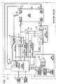
- a raster image processor (RIP) 10 receives a file of page generation instructions, called a display list, from an image source 12, such as a mainframe computer, personal computer, graphics work station, image scanner, or optical character recognition device, and generates bit map data for driving an all points addressable marking engine 14.
- the marking engine 14 may comprise for example a thermal, i ljet, dot matrix impact, or electrophotographic print er.
- the RIP includes interface and control electronics (ICE) 16 that controls the overall operation of the RIP and provides an interface with the image source 12 and the marking engine 14.
- ICE 16 may comprise a programmed microprocessor as is well known in the art.
- a page builder 18 receives page building instructions from the ICE 16 and generates bit map print data representing graphic objects and alphanumeric characters.
- the bit map print data is supplied from the page builder 18 as 16-bit words.
- Page builder 18 includes a graphics generator 20 for generating bit maps of graphic objects from primitive vector generating and trapezoid filling commands, and a character generator 22 for generating character bit maps from character defining code such as ASCII code.
- the character generator 22 retrieves the character bit maps as 16-bit words from a font memory 24.
- the page builder 18 may also receive original bit map data directly from the ICE 16, as illustrated by line 25. As illustrated schematically by OR gate 26, either graphic, character or original bit map data are supplied as 16-bit words by the page builder 18.
- the 16-bit words from page builder 18 are combined with clipping window and texture bit maps, as described below, in data conditioner 28.
- the RIP 10 also includes a page memory 30 where the bit map representation for a page is accumulated and stored prior to sending the printing instructions to the marking engine.
- the page memory 30 has a data input 32 for receiving a 16-bit word, a write enable input 34 for selectively enabling each one of the 16-bits in the input word, a read enable input 36, a data output 38, and a memory address input 40.
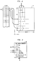
- the bit map data is organized in the page memory 30 as shown in Fig. 2.
- the 16-bit words 42 are stored consecutively in memory as shown by the illustration on the left in Fig. 2.
- the page 44 is composed of vertical strips 46, one bit wide, with n 16-bit words in each strip, as shown in the illustration to the right in Fig. 2.
- the page height PH (in the x direction) is the number n of 16-bit words in a vertical strip and the page width (in the y direction) is defined in bits.
- an 8 1/2 inch by 11 inch page would be 2550 bits wide by 207 words long.
- the x and y coordinates, expressed in bits (pixels) are each defined by 16-bit words.
- the 12 most significant bits of the x coordinate value expressed in-bits represent the x coordinate value expressed in 16-bit words.
- the four least significant bits of the x coordinate value define a shift value that is employed as explained below to selectively place a character or graphic object any where on the page in the x direction.
- a page address generator 48 generates the address for each 16-bit word that is to be stored in the page memory 30. The address is supplied as a 22 bit address to the address input 40 of the page memory 30.
- a tint generator 50 generates a bit pattern representing a halftone tint, and applies the bit pattern as 16-bit words to the data input 32 of the page memory 30.
- a clipping window generator 52 generates a bit pattern representing a clipping window mask and supplies the bit pattern, as 16-bit words, to data conditioner 28.
- a texture generator 54 generates a bit pattern representing a texture such as a checkerboard or diagonal stripes, and applies the texture bit pattern as 16-bit words to the data conditioner 28.
- the 16-bit output of data conditioner 28 is supplied to the write enable input 34 of the page memory 30. Each bit of the output from data conditioner 28 applied to the write enable input 34 enables a corresponding bit at the data input 32 of the page memory 30 to be written.
- the tint generator 50 receives a 6 bit tint level command from the ICE 16 specifying one of 64 possible tint patterns to be produced.
- the tint level command is held in a latch 60 and employed to address a tint memory 62 (for example a programmable read only memory).
- the three least significant bits of the y coordinate value from the ICE 16 are employed to address the particular byte in the tint pattern memory.
- each byte is duplicated as shown in Fig 5, and the duplicated bit pattern is supplied as 16-bit words to the data input 32 of page memory 30.
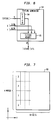
- the texture generator 54 receives a 5 bit texture command from ICE 16 that specifies one of 32 possible texture patterns to be produced.
- the texture command is held in a latch 64 and employed to address a texture memory 66.
- the texture patterns are stored in texture memory 66 as 64 by 64 bit blocks 68.
- the blocks are divided into 16-bit words in the x direction, such that each column of bits in the x direction is four words high.
- the words in a block are addressed by the two least significant bits of the x coordinate value expressed in words, and the five least significant bits of the y coordinate value.
- the 16-bit words are supplied one word at a time to the data conditioner 28.
- a rectangular clipping window 69 is defined by a lower limit x a ,y a and an upper limit x b ,y b on a page.
- the lower limit defines the bottom and left sides of the rectangular clipping window 69
- the upper limit defines the top and right side of the rectangular clipping window 69.
- the window generator 52 receives the upper and lower limits from the ICE 16 and latches these values in a set of latches 70.
- the latched values are supplied to a comparator 72 where they are compared with the current x,y coordinate values received from the x,y counters 57 in the ICE 16.
- ROM read only memory
- the results of the comparison are supplied to a read only memory (ROM) 74 that is programmed to produce a 16-bit word representing the window mask for the current word address.
- the 16-bit word representing the window mask is supplied to data conditioner 28. As shown in Fig. 9, portions of a line 76 within the window 69 will be printed, and portions of the line falling outside the window will be clipped (i.e. not printed).
- the data conditioner 28 receives bit map data from page builder 18, window mask data from window generator 52, and texture data from texture generator 54 and produces conditioned bit map data that is applied to the write enable input 34 of page memory 30.
- the page memory is organized as 16-bit words in the x direction.
- the data conditioner 28 is provided with a bit shifter 78.
- the bit shifter is a register that receives the 16-bit data word and loads it at a position indicated by a four bit shift command from the ICE 16.
- the four bit shift command is the four least significant bits of the 16-bit x coordinate value (expressed in bits).
- the first m bits of the bit shifter 78 are either loaded with 0's if it is the first word in a column, or with the leftover bits from the previous data word.
- the shifted bit map data is combined with the texture data from texture generator 54, and the window mask from window generator 52, as represented schematically in Fig. 1 by AND gate 80.
- Fig. 10 shows how the bit map data word is shifted with respect to the window mask and the texture data words to produce conditioned output bit map data words.
- the shift value is four bits (or pixels).
- the n th data word is the first word in a column, so the first four bits in the bit shifter are set to zero.
- the first four bits in the bit shifter are the last four bits left over from the n th word, and so on.
- the image source 12 supplies the display list as exemplified in Table I to the ICE 16.
- the ICE interprets the first command to set the page height to a value PH1 expressed in 16-bit words.
- the page height command is sent to the page address generator 48, where it is latched in latch 56.
- the page address generator will subsequently produce a page address in response to each pair of x,y coordinate values supplied by the x,y counters 57 in the ICE 16.
- the ICE 16 interprets the second command to set a clipping window, and sends the lower and upper clipping boundaries (x a ,y a ;x b ,y b ) to the clipping window generator 52.
- the clipping window generator 52 latches the clipping boundary values and produces 16-bit words with 1's inside the window, and 0's outside the window in response to the x,y coordinate values sent by the ICE 16.
- Fig. 11 shows a page 100, with the clipping window 102 outlined by dashed lines.
- the ICE 16 interprets the third command to select a specific tint pattern specified by T1, and sends a 6 bit tint level signal to the tint generator 50 to select the desired tint pattern in the tint memory 62.
- the tint generator 50 latches this level and produces 16-bit tint pattern words in response to the three least significant bits of the y coordinate values sent by ICE 16.
- the ICE interprets the fourth command to select a desired texture pattern in the texture memory 66 in the texture generator 54.
- the texture generator latches the texture value and produces 16-bit texture words in response to x and y coordinate values received from ICE 16.
- the fifth command is interpreted by the ICE to place a specified object at the specified location (x1,y1).
- the ICE 16 sends the 4 bit shift value (the four least significant bits of the x coordinate value) to the data conditioner 28 and instructs the page builder 18 to generate the bit pattern for the specified object.
- the object may be a filled rectangle 104 as shown in Fig. 11, which would be generated by the graphics generator 20.
- the graphics generator 20 produces 16-bit words representing the graphic object in response to the x,y coordinate values supplied by the ICE 16.
- ICE 16 causes the x,y counters 57 to generate the x,y coordinate values for all the 16-bit words in the object.
- the x,y coordinate values for each consecutive word of the graphic object are generated by x,y counters 57, the x,y coordinate values are also supplied to the page address generator 48, the tint generator 50, the clipping window generator 52, the texture generator 54 and the page builder 18.
- the page address generator 48 Upon receipt of the x,y coordinate values, the page address generator 48 generates and issues a page address to the page memory.
- the tint generator , clipping window generator, texture generator, and page builder each issue a 16-bit word for the indicated coordinate location.
- the 16-bit word from the page builder is shifted and combined with the 16-bit words from the texture generator and the clipping window within the data conditioner 28 and applied to the write enable input 34 of the page memory 30.
- the output of the tint generator 50 is applied to the data input of the page memory. If the memory is enabled, i.e. if the output of the data conditioner 28 contains a 1 at a particular location in the 16-bit word, the output of the tint generator 50 at the corresponding bit position will be written into memory. If the memory is not enabled, i.e. if the output of data conditioner 28 contains a 0, no change will be made to the current contents of the page memory.
- the first object written into memory is a rectangle 104 placed at location x1,y1 on the page 100.
- the portion of the rectangle falling outside the window 102 was not written into page memory 30 since the output of the clipping window generator 52 was 0 in this region.
- the rectangle is shaded with the selected tint pattern.
- the texture selected for Object 1 was a solid texture with no pattern. This solid texture is also a default option if no texture command is given in the command list.
- the ICE 16 interprets the sixth command to set a new tint pattern T2, (e.g. a solid or maximum density pattern where all the bits in the pattern are 1's) and sends the appropriate tint select signal to tint generator 50.
- the seventh command is interpreted to set a new texture pattern TX2 (e.g. a diagonal stripe pattern), and the texture select signal is sent to the the texture generator 54 to select the bit pattern for the selected texture.
- the ICE 16 interprets the eighth command to place object 2 (e.g. a block letter A) at location x2,y2.
- object 2 e.g. a block letter A
- the ICE 16 sends the appropriate shift command to the data conditioner, and has the x,y counters 57 send the x and y coordinate values of all the 16-bit words making up the character.
- the alphanumeric character is identified by an ASCII code and accompanying code that identifies the type font and character size.
- the character generator 22 in the page builder 18 responds to the code to retrieve the character bit map from the font memory 24.
- each data word is appropriately shifted and is combined with the corresponding texture and window bits by data conditioner 28 to produce a conditioned data word.
- the output of the data conditioner 28 is a 1, and the memory is enabled to receive an input on data input 32. Since the tint generator in this example is outputting all 1's (i.e. a maximum density tint), the textured character 106 is written into the page memory 30, as shown in Fig. 12. The portions of the character that lie outside the clipping window 102 are not written into the page memory 30, and are shown by dashed lines in Fig. 12.
- a wide box 110′ is again written into the page memory over a tall box 108′. This time however, in the resulting pattern 112′, the pattern of the tall box 108′ shows through in the area of intersection between the two boxes.
- the raster image processor is placed in the transparent mode of operation, by supplying the signal from the tint generator 50 to AND gate 80, as shown by dashed line 114, through a switch 116.
- the switch 116 With the switch 116 in the transparent mode position shown in Figure 1, 0's cannot be written into the page memory 30 since a 0 output from the tint generator 50 will cause the output of AND gate 80 to be 0, thereby preventing input to the memory.
- the switch 116 is controlled by ICE 16 to place the raster image processor 10 in the transparent or opaque mode of operation. In the opaque mode of operation, the switch 16 is placed in an alternate position, where a constant logical 1 is applied to AND gate 80.
- the present invention may be used to advantage to drive a color marking engine in either the opaque or transparent mode of operation.
- color images are defined in a hierarchical order, such that when graphic objects or alphanumeric characters overlap, objects that are higher in the hierarchy obscure underlying objects that are lower in the hierarchy.
- generating the bit maps for the color components of an opaque model color image was a computationally intensive process.
- the present invention substantially simplifies the computation by accumulating the color components in the page memory in the manner described above with reference to a monochromatic image.
- bit maps of the color components of a color image may be generated and printed one at a time (serial color), or all at once (parallel color).
- Serial color will be described first with reference to the exemplary display list contained in Table II below.
- the tint memory 62 contains a set of tint patterns for each of the primary color components produced by the marking engine.
- the halftone tint patterns for the color components may be spatially offset from each other to avoid dot overlap between the color components.
- the tint generator 50 also includes an input (shown by a dashed line) designating the particular color component to be generated. This is a two bit command to select, for example one of the four color components cyan (C), magenta (M), yellow (Y) or black (Bk). This command is latched into the latch 60 along with the tint level command, and is employed to address tint memory 62.
- the object and color components are initialized (200) by starting at the top of the display list and selecting a first color component to be processed (e.g. Black).
- a first color component to be processed e.g. Black
- the setup for placing the next object in memory is performed (206) by setting the parameters for the clipping window, the texture, and the tint level for the first color component.
- the bit map for the first object is generated and written into page memory (208) as described above for a monochrome image.
- a check is made (210) to see if this is the last object on the list. If not, the previous steps (206, 208) are repeated for the next object on the list..
- the color component is printed (212) by the marking engine.
- next color component e.g. cyan
- the process is started again.
- the bit map for the next color component is generated and printed (206, 208, 212). This process is continued till all the color components for a page have been printed.
- all the color component bit maps are compiled simultaneously in a "parallel process".
- a separate page memory 30, 30′, 30′′ and 30′′′ and a separate tint generator 50, 50′. 50′′ and 50′′′ is provided for each color component as illustrated schematically in Fig. 15.
- the three least significant bits of the y coordinate value from x,y counters 57 in ICE 16 are supplied to all the tint generators.
- Each tint generator receives a respective tint level command from ICE 16, and supplies its output to the corresponding data input 32 of its associated page memory.
- the conditioned page data from the data conditioner 28 is supplied in parallel to all the write enable inputs 34 of the page memories.
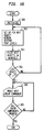
- the steps performed by the ICE 16 in implementing parallel color will be discussed.
- the process is initialized (300) by starting at the top of the list.
- setup for the first object is performed (302) by setting the clipping window, selecting the texture pattern, and setting the tint levels for each of the color components.
- the first object is then placed in page memory at location x1,y1 (304) by sending the conditioned page data to all of the write enable inputs 34 of the color component page memories simultaneously, and sending the respective tint patterns to the data inputs 32 of the color component page memories.
- a check is made (306) to see if this is the last object on the list. If not, the next setup is performed (302) and the next object is placed in memory (304) as described above.
- the first color component e.g. Black
- the first color component is printed (308) by reading out the contents of the memory holding the bit map for the first color component.
- a check is made (310) to see if all four colors have been printed. If not, the next color component is printed. This process continues until all the color components have been printed.
- the parallel process of operation saves time in generating the color component bit maps, at the expense of duplicating hardware (ie page memories and tint generators).
- the RIP according to the present invention is useful in the field of printing and in particular for driving an all points addressable marking engine.
- the RIP has the advantage of generating a bit map for driving the marking engine at a faster rate than the prior art RIP's, and is particularly advantageous for use with a color marking engine to produce images where the colors and textures of objects are separately and independently controlled.
- the RIP has the further advantage that the process of generating patterns, tints and windows proceeds automatically with the generation of the x and y coordinate values, without the need for algorithmic intervention by a central processing unit.
Landscapes
- Engineering & Computer Science (AREA)
- General Physics & Mathematics (AREA)
- Theoretical Computer Science (AREA)
- Physics & Mathematics (AREA)
- General Engineering & Computer Science (AREA)
- Image Generation (AREA)
- Dot-Matrix Printers And Others (AREA)
- Storing Facsimile Image Data (AREA)
- Fax Reproducing Arrangements (AREA)
- Color Image Communication Systems (AREA)
- Color, Gradation (AREA)
- Image Processing (AREA)
- Facsimile Image Signal Circuits (AREA)
Claims (20)
- Rasterbildprozessor mita) Speichermitteln (30) zum Speichern des Bitmusters einer mittels einer punktadressierbaren Druckvorrichtung (14) zu druckenden Seite;b) Farberzeugungsmitteln (50) zum Erzeugen eines eine Rasterfarbe darstellenden Bitmusters; undc) Datenerzeugungsmitteln (18, 28) zum Erzeugen eines Seitenbitmusters, welches eine Seite mit Objekten wie Zeichensätzen und Grafiken darstellt;dadurch gekennzeichnet, daß die Speichermittel einen einzigen Seitenspeicher (30) mit einem Daten-Eingang (32) und einem Schreibfreigabe-Eingang (34) aufweisen, wobei das Farberzeugungs-Bitmuster und das Seiten-Bitmuster an den Daten-Eingang (32) bzw. den Schreibfreigabe-Eingang angelegt werden.
- Rasterbildprozessor nach Anspruch 1, gekennzeichnet durcha) Strukturmustererzeugungsmittel (54) zum Erzeugen eines ein Strukturmuster darstellenden Bitmusters;b) Mittel (28, 80) zum Verknüpfen des Seiten-Bitmusters mit dem Struktur-Bitmuster zu einem kombinierten Bitmuster und zum Anlegen des kombinierten Bitmusters an den Schreibfreigabe-Eingang (34) des Seitenspeichers (30) anstelle des Seiten-Bitmusters.
- Rasterbildprozessor nach Anspruch 2, gekennzeichnet durch Fenstererzeugungsmittel (52) zum Erzeugen eines einen Fenster-Fenstererzeugungsmittel (52) zum Erzeugen eines einen Fensterausschnitt darstellenden Bitmusters, wobei die Verknüpfungsmittel (28, 80) das Fenster-Bitmuster mit dem Struktur- und Seiten-Bitmuster kombinieren.
- Rasterbildprozessor nach Anspruch 2, gekennzeichnet durch einen Seitenadreßgenerator (48), der x- und y-Seitenkoordinaten aufnimmt und eine Seitenspeicheradresse erzeugt, wobei der Seitenspeicher (30) einen Adresseneingang (40) zur Aufnahme der Seitenspeicheradresse aufweist, und wobei die Farberzeugungsmittel (50) und die Strukturerzeugungsmittel (54) die x- und y- Seitenkoordinaten aufnehmen und Ausgangswörter erzeugen, die Färbung bzw. Struktur darstellenden, sich wiederholenden Mustern entsprechen.
- Rasterbildprozessor nach Anspruch 3, gekennzeichnet durch einen Seitenadreßgenerator (48), der x- und y-Seitenkoordinaten aufnimmt und eine Seitenspeicheradresse erzeugt, wobei der Seitenspeicher (30) eine Seitenspeicheradreßeingabe zur Aufnahme der Seitenspeicheradresse aufweist, und wobei die Farberzeugungsmittel (50), die Strukturmustererzeugungsmittel (54) und die Fensterausschnitterzeugungsmittel (52) die x- und y-Seitenkoordinaten aufnehmen und ein Ausgangswort erzeugen, das einem sich wiederholenden, eine Färbung, ein Strukturmuster bzw. ein einen Fensterausschnitt darstellenden Muster entspricht.
- Rasterbildprozessor nach Anspruch 1, zur Verwendung mit einer Druckvorrichtung (14) zur Erzeugung von Farbausdrucken, wobei der Seitenspeicher eine Folge von Bitmustern speichert, die eine Folge von durch die Druckvorrichtung (14) zu druckenden Primärfarbenkomponenten darstellen, und wobei die Farberzeugungsmittel (50) ein ausgewähltes Farbmuster für jede Primärfarbenkomponente erzeugen, um ein Farbenspektrum zu erstellen.
- Rasterbildprozessor nach Anspruch 6, gekennzeichnet durch Mittel zum Einbringen des von den Farberzeugungsmitteln (50) erzeugten Farbmusters zwischen aufeinanderfolgende Primärfarbenkomponenten, um die Überlappung von Farbpunkten in einem von der Druckvorrichtung erzeugten Ausdruck auf ein Minimum zu reduzieren.
- Rasterbildprozessor nach Anspruch 1, 2 oder 3, gekennzeichnet durch Mittel (80, 116) zur UND-Verknüpfung des die Rasterfärbung darstellenden Bitmusters mit dem eine Objektseite darstellenden Bitmuster, und zum Anlegen des UND-verknüpften Bitmusters an den Schreibfreigabe-Eingang (34) des Seitenspreichers (30).
- Rasterbildprozessor nach einem der Ansprüche 1 - 8, dadurch gekennzeichnet, daß das Seitenbitmuster im Seitenspeicher (30) als Kette sequentiell numerierter n-Bit Wörter gespeichert ist und folgende Mittel aufweist:a) Mittel zum Erzeugen eines die Seitenhöhe in n-Bit Wörtern darstellenden Signals (PH);b) x-, y-Zählermittel (57) zum Erzeugen einer m-Bit x-Seitenkoordinate und einer m-Bit y-Seitenkoordinate;c) Seitenspeicheradreß-Erzeugunsmittel (48), die in Abhängigkeit von einem die Seitenhöhe und die x- und y-Seitenkoordinaten darstellenden Signal eine Seitenspeicheradresse nach der Formel

- Rasterbildprozessor nach Anspruch 9, dadurch gekennzeichnet, daß der Seitenspeicher (30) einen Daten-Eingang (32) und einen Schreibfreigabe-Eingang (34) sowie folgende Mittel aufweist:a) Seitenerstellungsmittel (18) aus Grafik und alphanumerischen Zeichen, wobei die Mittel (18) in Abhängigkeit von den x- und y-Koordinaten der x-, y-Zählermittel (57) ein n-Bit-Datenwort an den Schreibfreigabe-Eingang (34) des Seitenspeichers (30) liefern;b) Farberzeugungsmittel (50) zum Erzeugen eines eine Rasterfarbe darstellenden Bitmap-Musters, wobei die Mittel (50) in Abhängigkeit von den x- und y-Koordinaten der x-, y-Zählermittel (57) ein n-Bit-Farbwort an den Daten-Eingang (32) des Seitenspeichers liefern.
- Rasterbildprozessor nach Anspruch 10, gekennzeichnet durch Mittel (80, 116) zur UND-Verknüpfung der eine Rasterfarbe darstellenden Bitmap sowie der Daten-Bitmap, um eine UND-verknüpfte Bitmap zu bilden, und zum Anlegen der UND-verknüpften Bitmap anstelle der Daten-Bitmap an den Schreibfreigabe-Eingang (34) des Seitenspeichers (30).
- Rasterbildprozessor nach Anspruch 1 für eine punktadressierbare Druckvorrichtung mita) einem Seitenspeicher (30) zum Speichern einer Bitmap-Darstellung einer von der Druckvorrichtung (14) zu einem Seitenspeicher (30) zum Speichern einer Bitmapdruckenden Datenseite, wobei die Seite als bitweise Spalten von n-Bit-Wörtern angeordnet ist;b) Mitteln (20, 22, 24) zum Erzeugen von Daten-Bitmaps von Objekten wie Grafiken und alphanumerischen Zeichen, wobei die Daten-Bitmaps als Bit-Blöcke aus bitweisen Spalten von n-Bit-Datenwörtern gebildet werden;
gekennzeichnet durch Datenaufbereitungsmittel (80), die an jeder beliebigen Bitstelle auf einer Seite ein Datenwort plazieren und auf ein eine Verschiebung von m Bits darstellendes Signal ansprechen - wobei m ein Wert zwischen 0 und n-1 ist - zur Bildung von aufbereiteten, um m Bits von dem Datenwort verschobenen Datenwörtern, für das erste Wort in einer Spalte, wobei das aufbereitete Datenwort für die ersten m Bits und die ersten n-m Bits des Datenworts für die letzten auf aufbeteitete Datenwörter in einer Spalte folgenden n-m Bits Nullen enthält, wobei die die letzten m Bits des vorhergehenden Wortes bildenden Bits die ersten m Bits des aufbereiteten Datenworts bilden. - Rasterbildprozessor nach Anspruch 12, dadurch gekennzeichnet, daß der Seitenspeicher (30) einen Schreibfreigabe-Eingang (34) und einen Daten-Eingang (32) aufweist, gekennzeichnet durch
- Mittel (50) zum Bilden von Rasterfarbmuster darstellenden Bitmaps, wobei die Raster-Bitmaps als bitweise Spalten von n-Bit Wörtern aufweisende Bitblöcke gebildet werden, und wobei die Rasterfarbmusterwörter an den Daten-Eingang (32) des Seitenspeichers (30) und die aufbereiteten Datenwörter an den Schreibfreigabe-Eingang (34) des Speichers (30) angelegt werden. - Rasterbildprozessor nach Anspruch 13, gekennzeichnet durch Mittel (80, 116) zur UND-Verknüpfung der Rasterfarbmuster darstellenden Bitmaps und der aufbereiteten Datenwörter zur Bildung von UND-verknüpften Datenwörtern und Anlegen der UND-verknüpften Datenwörter anstelle der aufbereiteten Datenwörter an den Schreibfreigabe-Eingang (34) des Speichers (30).
- Rasterbildprozessor nach Anspruch 14, gekennzeichnet durcha) Mittel (54) zum Erzeugen von Strukturmuster-Bitmaps als bitweise Spalten von n-Bit Strukturwörtern aufweisende Bitblöcke;b) wobei die Datenaufbereitungsmittel (28) Mittel (80) aufweisen zur UND-Verknüpfung der Strukturmusterwörter mit den aufbereiteten Datenwörtern, um weitere aufbereitete Datenwörter zu bilden, die an den Schreibfreigabe-Eingang (34) des Seitenspeichers (30) angelegt werden.
- Rasterbildprozessor und Anspruch 14, gekennzeichnet durcha) Mittel (52) zum Erzeugen von Fensterausschnitt-Bitmaps als bitweise Spalten von n-Bit-Fensterausschnitt-Wörtern aufweisende Bitblöcke; undb) wobei die Datenaufbereitungsmittel (28) Mittel (80) aufweisen zur UND-Verknüpfung der Fensterausschnitt-Wörter mit den aufbereiteten Datenwörtern, um aufbereitete Datenwörter zu bilden, die an den Schreibfreigabe-Eingang (34) des Speichers (30) angelegt werden.
- Verfahren einer Bitmap-Seitenspeichersteuerung in einem Rasterbildprozessor mit folgenden Schritten:a) Erzeugen eines Datenbitmusters, welches eine Seite mit Objekten wie Zeichensätze und Grafiken darstellen;b) Erzeugen eines eine Rasterfarbe darstellenden Bitmusters;
gekennzeichnet durch folgenden Schritt:c) Anlegen des Farb-Bitmusters und des Daten-Bitmusters an einen Daten-Eingang (32) bzw. Schreibfreigabe-Eingang (34) eines Bitmap Seitenspeichers (30). - Verfahren zur Bitmap-Seitenspeichersteuerung nach Anspruch 17 mit folgenden Schritten:a) Erzeugen eines ein Strukturmuster darstellenden Bitmusters;b) Verknüpfen des Struktur-Bitmusters mit dem Daten-Bitmuster, um ein kombiniertes Bitmuster zu bilden; undc) Anlegen des kombinierten Bitmusters anstelle des Daten-Bitmusters an den Schreibfreigabe-Eingang (34) des Bitmap-Seitenspeichers (30).
- Verfahren nach Anspruch 18 mit folgenden Schritten:a) Erzeugen eines einen Fensterausschnitt darstellenden Bitmusters; undb) Verknüpfen des Fensterausschnitt-Bitmusters mit den Struktur- und Daten-Bitmustern zur Bildung eins kombinierten Bitmusters, das an den Schreibfreigabe-Eingang (34) des Seitenspeichers (30) angelegt wird.
- Verfahren nach Anspruch 17, gekennzeichnet durch die UND-Verknüpfung des die Rasterfarbe darstellenden Bitmusters mit dem Daten-Bitmuster, um ein verknüpftes Bitmuster zu bilden, und Anlegen des verknüpften Bitmusters anstelle des Daten-Bitmusters an den Schreibfreigabe-Eingang des Bitmap-Seitenspeichers.
Applications Claiming Priority (3)
| Application Number | Priority Date | Filing Date | Title |
|---|---|---|---|
| US07/236,811 US5003496A (en) | 1988-08-26 | 1988-08-26 | Page memory control in a raster image processor |
| US236811 | 1988-08-26 | ||
| PCT/US1989/003540 WO1990002386A1 (en) | 1988-08-26 | 1989-08-18 | Page memory control in a raster image processor |
Publications (2)
| Publication Number | Publication Date |
|---|---|
| EP0425583A1 EP0425583A1 (de) | 1991-05-08 |
| EP0425583B1 true EP0425583B1 (de) | 1994-11-30 |
Family
ID=22891067
Family Applications (2)
| Application Number | Title | Priority Date | Filing Date |
|---|---|---|---|
| EP89910320A Expired - Lifetime EP0396661B1 (de) | 1988-08-26 | 1989-08-18 | Steuerung eines seitenspeichers in einem rasterfarbbilsprozessor |
| EP89910392A Expired - Lifetime EP0425583B1 (de) | 1988-08-26 | 1989-08-18 | Steuerung eines seitenspeichers in einem rasterbildprozessor |
Family Applications Before (1)
| Application Number | Title | Priority Date | Filing Date |
|---|---|---|---|
| EP89910320A Expired - Lifetime EP0396661B1 (de) | 1988-08-26 | 1989-08-18 | Steuerung eines seitenspeichers in einem rasterfarbbilsprozessor |
Country Status (5)
| Country | Link |
|---|---|
| US (1) | US5003496A (de) |
| EP (2) | EP0396661B1 (de) |
| JP (2) | JPH04500182A (de) |
| DE (2) | DE68919700T2 (de) |
| WO (2) | WO1990002385A1 (de) |
Families Citing this family (55)
| Publication number | Priority date | Publication date | Assignee | Title |
|---|---|---|---|---|
| US5274364A (en) * | 1989-01-09 | 1993-12-28 | Industrial Technology Research Institute | Window clipping method and device |
| US5146554A (en) * | 1989-09-29 | 1992-09-08 | Eastman Kodak Company | Page memory control in a raster image processor employed for digital halftoning |
| US5237655A (en) * | 1990-07-05 | 1993-08-17 | Eastman Kodak Company | Raster image processor for all points addressable printer |
| DE4022081A1 (de) * | 1990-07-10 | 1992-01-16 | Siemens Ag | Verfahren zum drucken eines halbtonbildes |
| US5255360A (en) * | 1990-09-14 | 1993-10-19 | Hughes Aircraft Company | Dual programmable block texturing and complex clipping in a graphics rendering processor |
| US5276798A (en) * | 1990-09-14 | 1994-01-04 | Hughes Aircraft Company | Multifunction high performance graphics rendering processor |
| US5265203A (en) * | 1990-09-14 | 1993-11-23 | Hughes Aircraft Company | Hardware multiprocess scheduler in a graphics rendering processor |
| US5408539A (en) * | 1990-10-01 | 1995-04-18 | Finlay; David E. | Tessellating and quadding pels during image transfer |
| US5289570A (en) * | 1990-10-10 | 1994-02-22 | Fuji Xerox Co., Ltd. | Picture image editing system for forming boundaries in picture image data in a page memory device |
| JP3033844B2 (ja) * | 1990-11-28 | 2000-04-17 | 株式会社日立製作所 | 印刷制御装置 |
| CA2064643A1 (en) * | 1991-06-17 | 1992-12-18 | Robert Eric Vogelsberg | Hardware-assisted mapping for apa displays |
| JP3096103B2 (ja) * | 1991-08-30 | 2000-10-10 | キヤノン株式会社 | 画像処理装置及び方法 |
| US5537638A (en) * | 1991-10-25 | 1996-07-16 | Hitachi, Ltd. | Method and system for image mapping |
| JP2845384B2 (ja) * | 1991-11-14 | 1999-01-13 | キヤノン株式会社 | 画像処理装置 |
| US5359430A (en) * | 1992-05-15 | 1994-10-25 | Microsoft Corporation | Block-halftoning method and system with compressed error image |
| JP3046687B2 (ja) * | 1992-10-16 | 2000-05-29 | 大日本スクリーン製造株式会社 | 画像記録用データ作成装置 |
| US5442732A (en) * | 1992-12-10 | 1995-08-15 | Xerox Corporation | Print folder application for electronic reprographic systems |
| JP3413201B2 (ja) * | 1992-12-17 | 2003-06-03 | セイコーエプソン株式会社 | ウィンドウ型及び他の表示オペレーションのためのグラフィックス制御プレーン |
| US5452403A (en) * | 1992-12-23 | 1995-09-19 | Eastman Kodak Company | Process for selecting output levels for multi-level halftone in the presence of an unstable display device |
| US6147688A (en) * | 1993-06-28 | 2000-11-14 | Athena Design Systems, Inc. | Method and apparatus for defining and selectively repeating unit image cells |
| EP0643528B1 (de) * | 1993-09-14 | 2000-06-14 | Canon Kabushiki Kaisha | Bildverarbeitungsgerät zum Bearbeiten einer Bildmarkierung |
| US5578283A (en) * | 1994-12-30 | 1996-11-26 | Engelhard Corporation | Catalytic oxidation catalyst and method for controlling VOC, CO and halogenated organic emissions |
| US5642474A (en) * | 1995-03-06 | 1997-06-24 | Hewlett-Packard Company | Arbitrary masking technique for filling in shapes for display |
| JP2887572B2 (ja) * | 1995-04-07 | 1999-04-26 | 富士ゼロックス株式会社 | 画像出力装置および画像処理方法 |
| US5796411A (en) * | 1995-07-10 | 1998-08-18 | Moore Business Forms, Inc. | High resolution real time raster image processing system and method |
| US5886705A (en) * | 1996-05-17 | 1999-03-23 | Seiko Epson Corporation | Texture memory organization based on data locality |
| US5828814A (en) * | 1996-09-10 | 1998-10-27 | Moore Business Forms, Inc. | Reduced cost high resolution real time raster image processing system and method |
| US5895636A (en) | 1997-12-02 | 1999-04-20 | Engelhard Corporation | Catalytic compositions and methods for suppression of halogenation of organic compounds with oxidation products of halogenated organic compounds in gaseous emission streams |
| US6205181B1 (en) * | 1998-03-10 | 2001-03-20 | Chips & Technologies, Llc | Interleaved strip data storage system for video processing |
| WO1999066716A1 (en) | 1998-06-18 | 1999-12-23 | Sony Electronics Inc. | A method of and apparatus for partitioning, scaling and displaying video and/or graphics across several display devices |
| US6377276B1 (en) * | 1998-06-18 | 2002-04-23 | Sony Corporation | Bitmap animation of on-screen-display graphics over a distributed network and a clipping region having a visible window |
| US6593937B2 (en) | 1998-06-18 | 2003-07-15 | Sony Corporation | Method of and apparatus for handling high bandwidth on-screen-display graphics data over a distributed IEEE 1394 network utilizing an isochronous data transmission format |
| US6618048B1 (en) | 1999-10-28 | 2003-09-09 | Nintendo Co., Ltd. | 3D graphics rendering system for performing Z value clamping in near-Z range to maximize scene resolution of visually important Z components |
| US6717577B1 (en) | 1999-10-28 | 2004-04-06 | Nintendo Co., Ltd. | Vertex cache for 3D computer graphics |
| JP3488157B2 (ja) * | 1999-12-13 | 2004-01-19 | 大日本スクリーン製造株式会社 | 印刷システム、サーバーコントローラ、ユニットコントローラ |
| US6906823B1 (en) | 2000-05-15 | 2005-06-14 | International Business Machines Corporation | Input interface for a raster object memory in a method, system and program |
| US6651116B1 (en) | 2000-05-15 | 2003-11-18 | International Business Machines Corporation | Output interface for a raster object memory in a method, system and program |
| US7119813B1 (en) | 2000-06-02 | 2006-10-10 | Nintendo Co., Ltd. | Variable bit field encoding |
| US7034828B1 (en) | 2000-08-23 | 2006-04-25 | Nintendo Co., Ltd. | Recirculating shade tree blender for a graphics system |
| US7184059B1 (en) | 2000-08-23 | 2007-02-27 | Nintendo Co., Ltd. | Graphics system with copy out conversions between embedded frame buffer and main memory |
| US6700586B1 (en) | 2000-08-23 | 2004-03-02 | Nintendo Co., Ltd. | Low cost graphics with stitching processing hardware support for skeletal animation |
| US6825851B1 (en) | 2000-08-23 | 2004-11-30 | Nintendo Co., Ltd. | Method and apparatus for environment-mapped bump-mapping in a graphics system |
| US6811489B1 (en) | 2000-08-23 | 2004-11-02 | Nintendo Co., Ltd. | Controller interface for a graphics system |
| US7196710B1 (en) * | 2000-08-23 | 2007-03-27 | Nintendo Co., Ltd. | Method and apparatus for buffering graphics data in a graphics system |
| US6867781B1 (en) | 2000-08-23 | 2005-03-15 | Nintendo Co., Ltd. | Graphics pipeline token synchronization |
| US7061502B1 (en) | 2000-08-23 | 2006-06-13 | Nintendo Co., Ltd. | Method and apparatus for providing logical combination of N alpha operations within a graphics system |
| US6707458B1 (en) | 2000-08-23 | 2004-03-16 | Nintendo Co., Ltd. | Method and apparatus for texture tiling in a graphics system |
| US6636214B1 (en) | 2000-08-23 | 2003-10-21 | Nintendo Co., Ltd. | Method and apparatus for dynamically reconfiguring the order of hidden surface processing based on rendering mode |
| US6980218B1 (en) * | 2000-08-23 | 2005-12-27 | Nintendo Co., Ltd. | Method and apparatus for efficient generation of texture coordinate displacements for implementing emboss-style bump mapping in a graphics rendering system |
| US6937245B1 (en) * | 2000-08-23 | 2005-08-30 | Nintendo Co., Ltd. | Graphics system with embedded frame buffer having reconfigurable pixel formats |
| US7576748B2 (en) * | 2000-11-28 | 2009-08-18 | Nintendo Co. Ltd. | Graphics system with embedded frame butter having reconfigurable pixel formats |
| US7002591B1 (en) | 2000-08-23 | 2006-02-21 | Nintendo Co., Ltd. | Method and apparatus for interleaved processing of direct and indirect texture coordinates in a graphics system |
| US7538772B1 (en) | 2000-08-23 | 2009-05-26 | Nintendo Co., Ltd. | Graphics processing system with enhanced memory controller |
| JP3922568B2 (ja) * | 2002-03-18 | 2007-05-30 | 株式会社リコー | 画像処理装置、描画処理方法及び該方法を実行するためのプログラム |
| US20070035668A1 (en) * | 2005-08-11 | 2007-02-15 | Sony Corporation | Method of routing an audio/video signal from a television's internal tuner to a remote device |
Family Cites Families (19)
| Publication number | Priority date | Publication date | Assignee | Title |
|---|---|---|---|---|
| US4367533A (en) * | 1980-08-25 | 1983-01-04 | Xerox Corporation | Image bit structuring apparatus and method |
| US4412296A (en) * | 1981-06-10 | 1983-10-25 | Smiths Industries, Inc. | Graphics clipping circuit |
| US4584573A (en) * | 1981-07-20 | 1986-04-22 | Sharp Kabushiki Kaisha | Combined character and background pattern print control system |
| US4521770A (en) * | 1982-08-30 | 1985-06-04 | International Business Machines Corporation | Use of inversions in the near realtime control of selected functions in interactive buffered raster displays |
| JPS5960487A (ja) * | 1982-09-29 | 1984-04-06 | フアナツク株式会社 | カラ−デイスプレイ装置 |
| US4516139A (en) * | 1982-11-05 | 1985-05-07 | Sharp Kabushiki Kaisha | Print control system in a color image printer |
| DE3486390T3 (de) * | 1983-03-08 | 1999-05-12 | Canon K.K., Tokio/Tokyo | Bildverarbeitungsgerät. |
| US4616336A (en) * | 1983-05-11 | 1986-10-07 | International Business Machines Corp. | Independent image and annotation overlay with highlighting of overlay conflicts |
| JPS6030261A (ja) * | 1983-07-29 | 1985-02-15 | Toshiba Corp | 画像形成装置 |
| US4649513A (en) * | 1983-11-15 | 1987-03-10 | International Business Machines Corporation | Apparatus and method for processing system printing data records on a page printer |
| EP0153584B1 (de) * | 1984-02-21 | 1989-09-06 | DR.-ING. RUDOLF HELL GmbH | Verfahren und Einrichtung zum Aufzeichnen von Schriftzeichen |
| JPS60232596A (ja) * | 1984-05-02 | 1985-11-19 | 株式会社日立製作所 | マルチウインドウ表示方式 |
| US4730185A (en) * | 1984-07-06 | 1988-03-08 | Tektronix, Inc. | Graphics display method and apparatus for color dithering |
| US4821212A (en) * | 1984-08-08 | 1989-04-11 | General Electric Company | Three dimensional texture generator for computed terrain images |
| EP0212563B1 (de) * | 1985-08-14 | 1994-11-02 | Hitachi, Ltd. | Verfahren zur Anzeigesteuerung für ein System mit mehreren Bildausschnitten |
| NL8502686A (nl) * | 1985-10-02 | 1987-05-04 | Stamicarbon | Werkwijze voor het bereiden van granules en granules verkregen met deze werkwijze. |
| US4829455A (en) * | 1986-04-11 | 1989-05-09 | Quantel Limited | Graphics system for video and printed images |
| US4825390A (en) * | 1986-04-28 | 1989-04-25 | Texas Instruments, Inc. | Color palette having repeat color data |
| US4796203A (en) * | 1986-08-26 | 1989-01-03 | Kabushiki Kaisha Toshiba | High resolution monitor interface and related interfacing method |
-
1988
- 1988-08-26 US US07/236,811 patent/US5003496A/en not_active Expired - Lifetime
-
1989
- 1989-08-18 DE DE68919700T patent/DE68919700T2/de not_active Expired - Fee Related
- 1989-08-18 DE DE68921611T patent/DE68921611T2/de not_active Expired - Fee Related
- 1989-08-18 EP EP89910320A patent/EP0396661B1/de not_active Expired - Lifetime
- 1989-08-18 WO PCT/US1989/003539 patent/WO1990002385A1/en not_active Ceased
- 1989-08-18 WO PCT/US1989/003540 patent/WO1990002386A1/en not_active Ceased
- 1989-08-18 EP EP89910392A patent/EP0425583B1/de not_active Expired - Lifetime
- 1989-08-18 JP JP1509687A patent/JPH04500182A/ja active Pending
- 1989-08-18 JP JP1509343A patent/JPH03500998A/ja active Pending
Also Published As
| Publication number | Publication date |
|---|---|
| EP0425583A1 (de) | 1991-05-08 |
| JPH03500998A (ja) | 1991-03-07 |
| EP0396661A1 (de) | 1990-11-14 |
| DE68921611T2 (de) | 1996-04-04 |
| JPH04500182A (ja) | 1992-01-16 |
| WO1990002386A1 (en) | 1990-03-08 |
| DE68921611D1 (de) | 1995-04-13 |
| DE68919700T2 (de) | 1995-06-08 |
| US5003496A (en) | 1991-03-26 |
| WO1990002385A1 (en) | 1990-03-08 |
| DE68919700D1 (de) | 1995-01-12 |
| EP0396661B1 (de) | 1995-03-08 |
Similar Documents
| Publication | Publication Date | Title |
|---|---|---|
| EP0425583B1 (de) | Steuerung eines seitenspeichers in einem rasterbildprozessor | |
| CA2052011C (en) | Edge enhancement method and apparatus for dot matrix devices | |
| US5857067A (en) | Intelligent font rendering co-processor | |
| EP0167165B1 (de) | Verfahren und Apparat für Grafikanzeige | |
| US6101514A (en) | Anti-aliasing apparatus and method with automatic snap fit of horizontal and vertical edges to target grid | |
| EP0583101B1 (de) | Zeichenmusterverfahren und -gerät | |
| US5146554A (en) | Page memory control in a raster image processor employed for digital halftoning | |
| US5075779A (en) | Apparatus and method for interpreting image data for use in a raster plotter | |
| JPS60198688A (ja) | ペ−ジ・メ−クアツプ装置 | |
| EP0229539B1 (de) | Regeleinrichtung für Farben-Kurvenschreiber | |
| EP0575134A2 (de) | Verfahren und Gerät zum Drucken nach einer grafischen Sprache | |
| US5878194A (en) | Method and device for outputting multicolor document | |
| WO1988001767A1 (en) | Horizontal line processor of data to be printed out sequentially | |
| US4964067A (en) | Computer output printer with plotter emulation | |
| JP3305381B2 (ja) | ハーフトーン出力方式 | |
| JPH03112671A (ja) | 印刷装置 | |
| JPH1115458A (ja) | 文字形成装置 | |
| JPH04345866A (ja) | 印字装置及びその画面表示装置 | |
| JPH0450896A (ja) | 描画回路 | |
| JPH05158458A (ja) | 相対式フォント・デバイスで固定式フォント・データを利用する方法 | |
| JPH0876739A (ja) | ビットマップフォントの縮小画面表示方法および縮小画面表示装置 | |
| JPH0264697A (ja) | 文字処理装置および文字処理方法 | |
| JPH0764527A (ja) | カラー文字形成装置 | |
| JPH02310062A (ja) | アウトライトフォント |
Legal Events
| Date | Code | Title | Description |
|---|---|---|---|
| PUAI | Public reference made under article 153(3) epc to a published international application that has entered the european phase |
Free format text: ORIGINAL CODE: 0009012 |
|
| 17P | Request for examination filed |
Effective date: 19910219 |
|
| AK | Designated contracting states |
Kind code of ref document: A1 Designated state(s): AT BE CH DE FR GB IT LI LU NL SE |
|
| 17Q | First examination report despatched |
Effective date: 19930930 |
|
| RBV | Designated contracting states (corrected) |
Designated state(s): DE FR GB |
|
| GRAA | (expected) grant |
Free format text: ORIGINAL CODE: 0009210 |
|
| AK | Designated contracting states |
Kind code of ref document: B1 Designated state(s): DE FR GB |
|
| REF | Corresponds to: |
Ref document number: 68919700 Country of ref document: DE Date of ref document: 19950112 |
|
| ET | Fr: translation filed | ||
| PGFP | Annual fee paid to national office [announced via postgrant information from national office to epo] |
Ref country code: GB Payment date: 19950713 Year of fee payment: 7 |
|
| PGFP | Annual fee paid to national office [announced via postgrant information from national office to epo] |
Ref country code: FR Payment date: 19950818 Year of fee payment: 7 |
|
| PGFP | Annual fee paid to national office [announced via postgrant information from national office to epo] |
Ref country code: DE Payment date: 19950831 Year of fee payment: 7 |
|
| PLBE | No opposition filed within time limit |
Free format text: ORIGINAL CODE: 0009261 |
|
| STAA | Information on the status of an ep patent application or granted ep patent |
Free format text: STATUS: NO OPPOSITION FILED WITHIN TIME LIMIT |
|
| 26N | No opposition filed | ||
| PG25 | Lapsed in a contracting state [announced via postgrant information from national office to epo] |
Ref country code: GB Effective date: 19960818 |
|
| GBPC | Gb: european patent ceased through non-payment of renewal fee |
Effective date: 19960818 |
|
| PG25 | Lapsed in a contracting state [announced via postgrant information from national office to epo] |
Ref country code: FR Effective date: 19970430 |
|
| PG25 | Lapsed in a contracting state [announced via postgrant information from national office to epo] |
Ref country code: DE Effective date: 19970501 |
|
| REG | Reference to a national code |
Ref country code: FR Ref legal event code: ST |