EP0425676B1 - Digitalisierungsverfahren - Google Patents
Digitalisierungsverfahren Download PDFInfo
- Publication number
- EP0425676B1 EP0425676B1 EP90901887A EP90901887A EP0425676B1 EP 0425676 B1 EP0425676 B1 EP 0425676B1 EP 90901887 A EP90901887 A EP 90901887A EP 90901887 A EP90901887 A EP 90901887A EP 0425676 B1 EP0425676 B1 EP 0425676B1
- Authority
- EP
- European Patent Office
- Prior art keywords
- displacement
- amount
- displacement distance
- stylus
- point
- Prior art date
- Legal status (The legal status is an assumption and is not a legal conclusion. Google has not performed a legal analysis and makes no representation as to the accuracy of the status listed.)
- Expired - Lifetime
Links
Images


Classifications
-
- G—PHYSICS
- G05—CONTROLLING; REGULATING
- G05B—CONTROL OR REGULATING SYSTEMS IN GENERAL; FUNCTIONAL ELEMENTS OF SUCH SYSTEMS; MONITORING OR TESTING ARRANGEMENTS FOR SUCH SYSTEMS OR ELEMENTS
- G05B19/00—Program-control systems
- G05B19/02—Program-control systems electric
- G05B19/42—Recording and playback systems, i.e. in which the program is recorded from a cycle of operations, e.g. the cycle of operations being manually controlled, after which this record is played back on the same machine
- G05B19/4202—Recording and playback systems, i.e. in which the program is recorded from a cycle of operations, e.g. the cycle of operations being manually controlled, after which this record is played back on the same machine preparation of the program medium using a drawing, a model
- G05B19/4207—Recording and playback systems, i.e. in which the program is recorded from a cycle of operations, e.g. the cycle of operations being manually controlled, after which this record is played back on the same machine preparation of the program medium using a drawing, a model in which a model is traced or scanned and corresponding data recorded
Definitions
- the present invention relates to a digitizing method by which positional data are sequentially fetched while profiling the configuration of a model, and more specifically, to a digitizing method capable of creating NC data by which the flagging of a corner is reduced.
- Figure 5(a) is a diagram explaining a conventional digitizing method, wherein a stylus 2 is moved along a model 4 and respective points P11, P12, Vietnamese are sequentially sampled from a previous output point P10 at predetermined intervals. Therefore, the distance from the middle point of a straight line, connecting the previous output point P10 and a present sampling point, to an intermediate point among the sampling points sampled up to this time is determined, and when this distance exceeds a preset tolerance value, the sampling point is designated as an output point.
- the distance l16 which is determined when sampling has been executed up to a sampling point P16, satisfies this condition, and thus P16 is designated as an output point and NC data approximating a straight line between the output points P10 and P16 is output.
- the conventional method has a drawback in that the change of a configuration is determined by the middle point among the sampling points.
- Figure 5(b) is a diagram showing a case in which digitizing is executed by profiling a model 5 having a corner 5a, wherein a stylus 2 is moved along the model 5 and respective points P21, P22, ... are sequentially sampled at predetermined intervals from a previous output point P20.
- the distances determined by the above method with respect to sampling points P21 to P25 located in front of the corner 5a are zero and thus they are not designated as an output point. Instead, a sampling point P26 located after the corner 5a and having a distance l26 exceeding the tolerance amount is first designated as an output point, and as a result, NC data is created based on the straight line connecting the output points P20 and P26, which causes a flagging of the corner.
- an object of the present invention is to provide a digitizing method capable of creating NC data by which the flagging of a corner can be reduced.
- JP-A-6314830 discloses a tracing apparatus with sharp edge detection.
- a method for digitising the surface of a model using a profiling stylus and for outputting NC data including the steps of:
- the amount of displacement of each axis is made equal to the reference amount of displacement when a gently inclined configuration is profiled, when a corner is reached the stylus 2 is spaced from a model, and accordingly, the difference between the amount of displacement and the reference amount of displacement is increased. This change is sensed and considered to show the corner, and thus the difference is added to the output point obtained by a usual digitising and the positional data at that time is output.
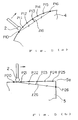
- Figure 1 is a conceptual view of a digitizing method of the embodiment according to the present invention.
- profiling is carried out on the X-axis direction in Figure 1, it can be carried out in any directions in the X-Y plane.
- a stylus 2 is moved in the X-axis direction at a predetermined profiling speed and moved upward and downward also in the Z-axis direction along the configuration of a model 1, and the amounts of displacement of the respective axes ⁇ x, ⁇ y, and ⁇ z are sensed by a tracer head 3. Namely, respective points P1, P2, ...
- sampling point P1, P2, P3, P4 and P5 cannot serve as the output point.
- the stylus 2 When the corner 1a of the model 1 is profiled, the stylus 2 is abruptly moved in the negative direction of the Z-axis by an amount of ⁇ z, and thus the composite amount of replacement ⁇ is instantaneously made smaller than the reference amount of displacement ⁇ 0.
- Figure 2 shows the change of the composite amount of replacement ⁇ , wherein a vertical axis represents a difference ⁇ between the reference amount of displacement ⁇ 0 and the composite amount of replacement ⁇ , a horizontal axis represents a time during which the stylus 2 is moved, and t6 corresponds to a timing at which the stylus 2 reaches the corner 1a shown in Figure 1.
- the difference ⁇ is within the range of from q1 to -q1 in the gently inclining range of the model 1, but when the stylus 2 reaches the corner 1a, it exceeds q1. This state is sensed and the position of the stylus 2 at the time is fetched and designated as an output point.
- a point P6 is designated as the output point next to the output point P0, and at the same tine, NC data to which a speed command suitable to the corner is added is output. Thereafter, points P7, P8, ... are sampled from the point P6 at predetermined intervals.
- NC data approximating a straight line between the output points P0 and P6 is obtained and machining in the vicinity of the output point P6 is carried out at a feed speed for the corner, whereby the configuration of the corner 1a can be correctly reproduced.
- Figure 3 is a flowchart showing the processes for machining the corner when executed by the digitizing method of the embodiment according to the present invention, wherein numerals prefixed with an S indicate the numbers of the steps of these processes.
- a difference ⁇ between the reference amount of displacement ⁇ 0 and a composite amount of displacement ⁇ exceeds a predetermined threshold value is determined at S1, and when the former exceeds the latter, the process goes to step S2, and when the former does not exceed the latter, digitizing is continuously carried out at predetermined sampling intervals.
- step S2 positional data at the point is output, and a speed command for the corner is output at step S3.
- FIG. 4 is a block diagram of hardware embodying the present invention, wherein a digitizer 10 comprises a processor 10a, a ROM 10b in which a control program is stored, a RAM 10c in which digitized positional data is stored, and a working memory 10d, by which the present position of a tracer head 3 is fetched and digitized while executing a profiling control.
- a digitizer 10 comprises a processor 10a, a ROM 10b in which a control program is stored, a RAM 10c in which digitized positional data is stored, and a working memory 10d, by which the present position of a tracer head 3 is fetched and digitized while executing a profiling control.
- An operator's panel 11 outputs various operation signals and functions to set profiling conditions, a profiling range and method, and the like.
- D/A converters 20X, 20Y and 20Z convert digital speed data in the respective axial directions commanded by the digitizer 10 to analog speed signals Vx, Vy and Vz and output the same to servo circuits 21X, 21Y and 21Z.
- These servo circuits enable servomotors 22X, 22Y and 22Z, which when rotated by a predetermined angle, cause pulse generators 23X, 23Y and 23Z to generate pulse signals Xf, Yf and Zf.
- a present position register 24 reversibly calculates these respective pulse signals to store the present positions of the respective axes and input same to the digitizer 10.
- the present embodiment senses the corner by comparing the composite amount of displacement with the reference amount of displacement, the amount of displacement of a particular axis may be compared with the reference amount of displacement.
- NC data capable of correctly reproducing the configuration of the corner can be provided.
- a speed command for the corner is added at the same time, and thus a configuration of the corner without flagging can be actually machined.
Landscapes
- Physics & Mathematics (AREA)
- General Physics & Mathematics (AREA)
- Engineering & Computer Science (AREA)
- Automation & Control Theory (AREA)
- Numerical Control (AREA)
- Machine Tool Copy Controls (AREA)
Claims (2)
- Verfahren zum Digitalisieren der Oberfläche eines Modells (1) unter Verwendung einer Tastspitze und zum Ausgeben von NC Daten mit folgenden Schritten:Positionsdaten gemäß einem bestimmten Verfahren werden nacheinander ausgegeben;eine Verschiebungsgröße für jede Achse, die für die Tastspitze (2) vorgesehen ist, wird von einem Abtastkopf (3) erfaßt und hieraus eine Verschiebungsgröße bestimmt und die Oberfläche wird profiliert, während die Tastspitze derart gesteuert wird, daß versucht wird, die Verschiebungsgröße gleich einer Bezugsgröße der Verschiebung zu machen, gekennzeichnet durch die Schritte:eine Differenz zwischen der Verschiebungsgröße und der Bezugsgröße der Verschiebung wird überwacht und zusätzlich zu den Positionsdaten, die man mit dem vorbestimmten Verfahren erhält, werden spezifische Positionsdaten ausgegeben, die man erhält, wenn die besagte Differenz einen bestimmten Wert überschreitet,die Verschiebungsgröße wird als eine Bezugsgröße der Verschiebung eingesetzt unddas Abtasten der Verschiebungsgröße erfolgt erneut.
- Digitalisierverfahren nach Anspruch 1, bei dem ein zum Bearbeiten einer Ecke passender Geschwindigkeitsbefehl zusammen mit den spezifischen Positionsdaten ausgegeben wird.
Applications Claiming Priority (3)
| Application Number | Priority Date | Filing Date | Title |
|---|---|---|---|
| JP2643789A JPH0763922B2 (ja) | 1989-02-03 | 1989-02-03 | デジタイジング方法 |
| JP26437/89 | 1989-02-03 | ||
| PCT/JP1990/000055 WO1990008624A1 (fr) | 1989-02-03 | 1990-01-17 | Procede de numerisation |
Publications (3)
| Publication Number | Publication Date |
|---|---|
| EP0425676A1 EP0425676A1 (de) | 1991-05-08 |
| EP0425676A4 EP0425676A4 (en) | 1993-04-07 |
| EP0425676B1 true EP0425676B1 (de) | 1996-05-01 |
Family
ID=12193484
Family Applications (1)
| Application Number | Title | Priority Date | Filing Date |
|---|---|---|---|
| EP90901887A Expired - Lifetime EP0425676B1 (de) | 1989-02-03 | 1990-01-17 | Digitalisierungsverfahren |
Country Status (4)
| Country | Link |
|---|---|
| EP (1) | EP0425676B1 (de) |
| JP (1) | JPH0763922B2 (de) |
| DE (1) | DE69026789T2 (de) |
| WO (1) | WO1990008624A1 (de) |
Families Citing this family (2)
| Publication number | Priority date | Publication date | Assignee | Title |
|---|---|---|---|---|
| JPH03213252A (ja) * | 1990-01-16 | 1991-09-18 | Fanuc Ltd | ならいの速度制御方式 |
| WO2014134108A1 (en) * | 2013-02-28 | 2014-09-04 | Corning Incorporated | Method of cooling glass ribbon in a fusion draw |
Family Cites Families (3)
| Publication number | Priority date | Publication date | Assignee | Title |
|---|---|---|---|---|
| JPS62176729A (ja) * | 1986-01-30 | 1987-08-03 | Mitsubishi Heavy Ind Ltd | 倣い軌跡のデイジタイジング方法 |
| JP2515526B2 (ja) * | 1986-12-12 | 1996-07-10 | オークマ 株式会社 | Ncデ−タ作成装置におけるデジタイズデ−タの出力方法 |
| JPH06274555A (ja) * | 1993-03-19 | 1994-09-30 | Babcock Hitachi Kk | 図面データ管理装置 |
-
1989
- 1989-02-03 JP JP2643789A patent/JPH0763922B2/ja not_active Expired - Lifetime
-
1990
- 1990-01-17 WO PCT/JP1990/000055 patent/WO1990008624A1/ja not_active Ceased
- 1990-01-17 EP EP90901887A patent/EP0425676B1/de not_active Expired - Lifetime
- 1990-01-17 DE DE69026789T patent/DE69026789T2/de not_active Expired - Fee Related
Also Published As
| Publication number | Publication date |
|---|---|
| DE69026789T2 (de) | 1996-09-05 |
| JPH0763922B2 (ja) | 1995-07-12 |
| DE69026789D1 (de) | 1996-06-05 |
| JPH02205442A (ja) | 1990-08-15 |
| EP0425676A1 (de) | 1991-05-08 |
| WO1990008624A1 (fr) | 1990-08-09 |
| EP0425676A4 (en) | 1993-04-07 |
Similar Documents
| Publication | Publication Date | Title |
|---|---|---|
| US5067086A (en) | Three-dimensional shape machining laser device | |
| EP0046032B1 (de) | Verfahren zur numerischen Steuerung | |
| EP0323276A2 (de) | Bahnerzeugungssystem für einen Voraussensor in einem System zur Robotersteuerung | |
| US4994977A (en) | Method of detecting an interference in the control of a plurality of mechanical systems | |
| EP0425676B1 (de) | Digitalisierungsverfahren | |
| US5193282A (en) | Rotating body tracing control apparatus | |
| EP0417307A1 (de) | Zeichnungsverfahren für numerische datenprogramme | |
| US5317517A (en) | Digitizing method | |
| EP0113682B1 (de) | Numerisches Steuerungssystem und Verfahren | |
| EP0314795B1 (de) | Digitalisierungsverfahren | |
| JPH04331048A (ja) | ならい制御装置 | |
| EP0037720A2 (de) | Verfahren zur Maschinenbearbeitung mittels numerischer Daten | |
| JPH02152748A (ja) | 数値制御用工作機械のストロークエンドチェック装置 | |
| US5583409A (en) | Numerical control apparatus and method for controlling a machine | |
| GB1235555A (en) | Improvements in or relating to numerical control systems | |
| JPH05165514A (ja) | 数値制御装置の補間方式 | |
| JPH0729256B2 (ja) | 工具交換位置教示方法 | |
| JPH02274457A (ja) | ならい制御装置 | |
| JPS58181106A (ja) | 数値制御式工作機械 | |
| JP2554757B2 (ja) | 三次元加工プログラム作成方法 | |
| EP0615179B1 (de) | Numerische steuerung | |
| EP0596241A2 (de) | Steuerungsschaltung für hochpräzise Bahnvervolgung welche eine multiaxiale Koordination verwendet | |
| WO2000019285A1 (en) | Process and system for working a workpiece through numerically controlled machine tools | |
| EP0371142A1 (de) | Korrekturverfahren für geometrische stellen bei industriellen robotern | |
| JPS6165309A (ja) | 基準点位置信号出力方式 |
Legal Events
| Date | Code | Title | Description |
|---|---|---|---|
| PUAI | Public reference made under article 153(3) epc to a published international application that has entered the european phase |
Free format text: ORIGINAL CODE: 0009012 |
|
| 17P | Request for examination filed |
Effective date: 19901018 |
|
| AK | Designated contracting states |
Kind code of ref document: A1 Designated state(s): DE FR GB IT |
|
| A4 | Supplementary search report drawn up and despatched |
Effective date: 19930218 |
|
| AK | Designated contracting states |
Kind code of ref document: A4 Designated state(s): DE FR GB IT |
|
| 17Q | First examination report despatched |
Effective date: 19941227 |
|
| GRAH | Despatch of communication of intention to grant a patent |
Free format text: ORIGINAL CODE: EPIDOS IGRA |
|
| GRAA | (expected) grant |
Free format text: ORIGINAL CODE: 0009210 |
|
| AK | Designated contracting states |
Kind code of ref document: B1 Designated state(s): DE FR GB IT |
|
| PG25 | Lapsed in a contracting state [announced via postgrant information from national office to epo] |
Ref country code: FR Effective date: 19960501 |
|
| ITF | It: translation for a ep patent filed | ||
| REF | Corresponds to: |
Ref document number: 69026789 Country of ref document: DE Date of ref document: 19960605 |
|
| EN | Fr: translation not filed | ||
| PG25 | Lapsed in a contracting state [announced via postgrant information from national office to epo] |
Ref country code: GB Effective date: 19970117 |
|
| PLBE | No opposition filed within time limit |
Free format text: ORIGINAL CODE: 0009261 |
|
| STAA | Information on the status of an ep patent application or granted ep patent |
Free format text: STATUS: NO OPPOSITION FILED WITHIN TIME LIMIT |
|
| 26N | No opposition filed | ||
| GBPC | Gb: european patent ceased through non-payment of renewal fee |
Effective date: 19970117 |
|
| PGFP | Annual fee paid to national office [announced via postgrant information from national office to epo] |
Ref country code: DE Payment date: 19980123 Year of fee payment: 9 |
|
| PG25 | Lapsed in a contracting state [announced via postgrant information from national office to epo] |
Ref country code: DE Free format text: LAPSE BECAUSE OF NON-PAYMENT OF DUE FEES Effective date: 19991103 |
|
| PG25 | Lapsed in a contracting state [announced via postgrant information from national office to epo] |
Ref country code: IT Free format text: LAPSE BECAUSE OF NON-PAYMENT OF DUE FEES;WARNING: LAPSES OF ITALIAN PATENTS WITH EFFECTIVE DATE BEFORE 2007 MAY HAVE OCCURRED AT ANY TIME BEFORE 2007. THE CORRECT EFFECTIVE DATE MAY BE DIFFERENT FROM THE ONE RECORDED. Effective date: 20050117 |