EP0425865A1 - Faltenbalg - Google Patents
Faltenbalg Download PDFInfo
- Publication number
- EP0425865A1 EP0425865A1 EP90119575A EP90119575A EP0425865A1 EP 0425865 A1 EP0425865 A1 EP 0425865A1 EP 90119575 A EP90119575 A EP 90119575A EP 90119575 A EP90119575 A EP 90119575A EP 0425865 A1 EP0425865 A1 EP 0425865A1
- Authority
- EP
- European Patent Office
- Prior art keywords
- folds
- opening angle
- collar
- flanks
- bellows
- Prior art date
- Legal status (The legal status is an assumption and is not a legal conclusion. Google has not performed a legal analysis and makes no representation as to the accuracy of the status listed.)
- Granted
Links
Images
Classifications
-
- F—MECHANICAL ENGINEERING; LIGHTING; HEATING; WEAPONS; BLASTING
- F16—ENGINEERING ELEMENTS AND UNITS; GENERAL MEASURES FOR PRODUCING AND MAINTAINING EFFECTIVE FUNCTIONING OF MACHINES OR INSTALLATIONS; THERMAL INSULATION IN GENERAL
- F16J—PISTONS; CYLINDERS; SEALINGS
- F16J3/00—Diaphragms; Bellows; Bellows pistons
- F16J3/04—Bellows
- F16J3/041—Non-metallic bellows
- F16J3/042—Fastening details
-
- F—MECHANICAL ENGINEERING; LIGHTING; HEATING; WEAPONS; BLASTING
- F16—ENGINEERING ELEMENTS AND UNITS; GENERAL MEASURES FOR PRODUCING AND MAINTAINING EFFECTIVE FUNCTIONING OF MACHINES OR INSTALLATIONS; THERMAL INSULATION IN GENERAL
- F16D—COUPLINGS FOR TRANSMITTING ROTATION; CLUTCHES; BRAKES
- F16D3/00—Yielding couplings, i.e. with means permitting movement between the connected parts during the drive
- F16D3/84—Shrouds, e.g. casings, covers; Sealing means specially adapted therefor
- F16D3/843—Shrouds, e.g. casings, covers; Sealing means specially adapted therefor enclosed covers
- F16D3/845—Shrouds, e.g. casings, covers; Sealing means specially adapted therefor enclosed covers allowing relative movement of joint parts due to the flexing of the cover
Definitions
- the invention relates to a bellows with a plurality of double-cone-shaped circumferential folds made of thin-walled thermoplastic elastomer, with collar regions of different diameters, in particular for sealing constant-velocity rotary joints.
- Bellows of the type mentioned are known for example from DE 34 17 709 A1. It is provided that, at least in the larger-diameter folds, the front flanks facing the larger collar have a larger opening angle to the axis than the flanks facing the smaller collar, this ratio changing along the length of the bellows as well as the height of the folds leading to the smaller Federal government increases.
- bellows of this shape made of rigid thermoplastic elastomer, e.g. made of a material such as Hytrel (registered trademark of the Dupont company) or Santoprene (registered trademark of the Monsanto company), when bending the bellows by bending the enclosed joint, increase the stress on the bellows Radial outer areas of the flanks in the vicinity of the pleat tips occurs, since the outer areas near the pleat tips are first in contact and thus lead to locally increased wear.
- the process described above first occurs on individual ones of the folds, on which a particularly large load thereby occurs.
- noisy folding of individual folds can take place, in particular with the joint bent at the same time, which can also lead to damage due to the increased deformation work.
- flanks facing the larger collar have a certain intrinsic stiffness and move axially or by bending to each other, while the flanks facing the smaller collar have the effect of an elastic membrane with low stiffness mentioned movements of the first mentioned flanks elastically.
- flanks facing the small collar are designed to be particularly flat with opening angles of 70 to 85 °.
- the assembly generally results in a certain shortening of the bellows, so that the angles mentioned are somewhat larger during operation.
- the uniformity of the folds results in a uniformity in their deformation, which causes the opposite flanks of adjacent folds to lie approximately simultaneously, so that increased forces due to early contact with individual flank pairs are avoided.
- flanks themselves are preferably designed as purely cone-shaped surfaces, so that the contact between the folds to reduce local contact pressure peaks initially occurs in the form of a generatrix.
- a longitudinally U-shaped connecting ring body with a narrow opening width of, for example, 2 mm is provided on the inside between the flanks, adjacent folds.
- the wall thickness ratio of fold valley to fold tip is to be kept in a size range of ⁇ 2: 1.
- the wall thickness at the tip of the fold should be ⁇ 1 mm, i.e. very thin-walled, to increase flexibility.
- the blowing process is preferably used to produce the bellows mentioned.
- the bellows shown comprises the two collar regions 1 and 2, from each of which a largest fold 3 and a smallest fold 4 are formed. In between there are three similar larger full folds 5 to 7 and a smaller fold 8.
- the peaks and valleys of the larger folds are enveloped by cones K1, K2 of the same opening angle ⁇ , which have an opening angle of approximately 10 ° to the axis of rotation A.
- the folds 5 to 7 each have a flank 9 facing the larger collar with an opening angle ⁇ of approximately 45 ° to the longitudinal axis and a steeper flank 10 facing the smaller collar with an opening angle ⁇ of approximately 65 ° to the axis.
- U-shaped connecting rings 11 are provided in the longitudinal section.
Landscapes
- Engineering & Computer Science (AREA)
- General Engineering & Computer Science (AREA)
- Mechanical Engineering (AREA)
- Diaphragms And Bellows (AREA)
Abstract
Description
- Die Erfindung betrifft einen Faltenbalg mit mehreren doppelkonusförmig umlaufenden Falten aus dünnwandigem thermoplastischen Elastomer, mit Bundbereichen unterschiedlichen Durchmessers, insbesondere zur Abdichtung von Gleichlaufdrehgelenken.
- Faltenbälge der genannten Art sind beispielsweise aus der DE 34 17 709 A 1 bekannt. Hierbei ist vorgesehen, daß zumindest bei den durchmessergrößeren Falten die zum größeren Bund gerichteten Vorderflanken einen größeren Öffnungswinkel zur Achse aufweisen als die zum kleineren Bund gerichteten Flanken, wobei sich dieses Verhältnis über der Länge des Faltenbalges ebenso verändert wie die Höhe der Falten, die zum kleineren Bund hin zunimmt.
- Die Praxis zeigt, daß an Bälgen dieser Form aus steifem thermoplastischem Elastomer, z.B. aus einem Material wie Hytrel (eingetragenes warenzeichen der Firma Dupont) oder Santoprene (eingetragenes Warenzeichen der Firma Monsanto) beim Abbeugen des Faltenbalges durch Beugebewegungen des eingeschlossenen Gelenks eine erhöhte Belastung an den radialen Außenbereichen der Flanken in der Nähe der Faltenspitzen auftritt, da zuerst an den Außenbereichen nahe der Faltenspitzen eine Anlage erfolgt und damit dort zu einem örtlich erhöhten Verschleiß führt. Bei axialen Einfedern infolge eines Zusammenschiebens des eingeschlossenen Gelenks erfolgt aufgrund der ungleichen Form der Falten der zuvor beschriebene Vorgang zuerst an einzelnen der Falten, an denen dadurch eine besonders große Belastung auftritt. Weiterhin kann aufgrund der Form der größeren Falten ein geräuschbehaftetes Umklappen von einzelnen Falten erfolgen, insbesondere bei zugleich gebeugtem Gelenk, das aufgrund der erhöhten Formänderungsarbeit auch zu Schäden führen kann.
- Hiervon ausgehend ist es Aufgabe der vorliegenden Erfindung, einen Faltenbalg der eingangs genannten Art so auszugestalten, daß die den Verschleiß am Faltenbalg bestimmenden Kräfte bei der Anlage sich gegenüberliegender Faltenflanken bei gebeugtem und/oder axial verkürzten Faltenbalg möglichst gering sind. Die Lösung hierfür besteht darin, daß in entspanntem Zustanddie zum kleineren Bund gerichteten Flanken der Falten einen Öffnungswinkel von mindestens 60° zur Rotationsachse haben und daß die zum größeren Bund gerichteten Flanken der Falten einen Öffnungswinkel von weniger als 50° zur Rotationsachse bilden und daß zumindest die beiden größeren Falten im wesentlichen gleichförmig mit jeweils gleichen Flankenhöhen ausgeführt sind, so daß sie innerhalb zweier außen- und innentangierender Konen mit gleichem Öffnungswinkel liegen. Hierdurch entsteht ein hochflexibler Faltenbalg, bei dem die jeweils zum größeren Bund gerichteten Flanken eine gewisse Eigensteifigkeit haben und sich insgesamt axial oder durch Abwinkelung zueinander verschieben, während die jeweils zum kleineren Bund gerichteten Flanken die Wirkung einer elastischen Membran mit demgegenüber geringer Formsteifigkeit aufweisen, die die genannten Bewegungen der erstgenannten Flanken elastisch aufnehmen.
- Nach einer besonders günstigen Ausführung sind dabei die zum kleinen Bund gerichteten Flanken besonders flach mit Öffnungswinkeln von 70 bis 85° ausgestaltet. Mit der Montage erfolgt in der Regel eine gewisse Verkürzung des Faltenbalges, so daß die genannten Winkel im Betrieb jeweils etwas größer sind.
- Durch die Gleichförmigkeit der Falten kommt eine Gleichförmigkeit ihrer Verformung zustande, die ein etwa gleichzeitiges Anliegen der sich gegenüberliegenden Flanken benachbarter Falten bewirkt, so daß erhöhte Kräfte durch frühzeitiges Anliegen an einzelnen Flankenpaarungen vermieden werden.
- In Weiterführung dieses Gedankens sind insbesondere mit Ausnahme der kleinsten vollständigen Falte sämtliche vollständigen Falten innerhalb der genannten Konen mit gleichem Öffnungswinkel gleichartig ausgeführt.
- Bevorzugt sind die Flanken selber als rein kegelabschnittsförmige Flächen ausgeführt, so daß die Anlage zwischen den Falten zur Reduzierung örtlicher Anlagedruckspitzen zunächst mantellinienförmig zustande kommen.
- In an sich bekannter Ausführung ist zwischen den Flanken, benachbarter Falten innen ein im Längsschnitt U-förmiger Verbindungsringkörper geringer Öffnungsbreite von beispielsweise 2 mm vorgesehen. Das Wandstärkenverhältnis von Faltental zu Faltenspitze ist in einem Größenbereich von < 2 : 1 zu halten. Dabei soll die Wandstärke an der Faltenspitze ≦ 1 mm sein, das heißt sehr dünnwandig, um die Flexibilität zu erhöhen.
- Zur Herstellung der genannten Faltenbälge wird bevorzugt das Blasverfahren angewandt.
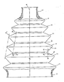
- Ein bevorzugtes Ausführungsbeispiel eines erfindungsgemäßen Faltenbalges ist in der Figur dargestellt.
- Der gezeigte Faltenbalg umfaßt die zwei Bundbereiche 1 und 2, aus denen jeweils eine größte Falte 3 und eine kleinste Falte 4 ausgeformt sind. Dazwischen liegen drei untereinander gleichartige größere vollständige Falten 5 bis 7 und eine kleinere Falte 8. Die Spitzen und Täler der größeren Falten werden durch Konen K₁, K₂ gleichen Öffnungswinkels γ eingehüllt, die einen Öffnungswinkel von ca. 10° zur Rotationsachse A haben. Die Falten 5 bis 7 haben jeweils eine zum größeren Bund gerichtete Flanke 9 mit einem Öffnungswinkel α von ca. 45° zur Längsachse und einen zum kleineren Bund gerichtete steilere Flanke 10 mit einem Öffnungswinkel β von ca 65° zur Achse. Jeweils zwischen zwei Falten sind im Längs schnitt U-förmige Verbindungsringe 11 vorgesehen.
-
- 1 Bund (groß)
- 2 Bund (klein)
- 3 Falte (groß)
- 4 Falte (klein)
- 5, 6, 7 Falten
- 8 Falte
- 9 Flanke
- 10 Flanke
- 11 Verbindungsring
Claims (7)
dadurch gekennzeichnet,
daß im entspannten Zustand die zum kleineren Bund (2) gerichteten Flanken (10) der Falten einen Öffnungswinkel von mindestens 60° zur Rotationsachse haben und daß die zum größeren Bund (1) gerichteten Flanken (9) der Falten einen Öffnungswinkel von weniger als 50° zur Rotationsachse bilden, und
daß Zumindest die beiden größten vollständigen Falten (5, 6) gleiche Flankenhöhen aufweisen und somit von zwei Konen gleichen Öffnungswinkels außen und innen eingehüllt werden.
dadurch gekennzeichnet,
daß die zum kleineren Bund (2) gerichteten Flanken (10) der Falten einen Öffnungswinkel von 70 bis 85° zur Rotationsachse aufweisen.
dadurch gekennzeichnet,
daß mit Ausnahme der kleinsten vollständigen Falte (8) alle vollständigen Falten (5, 6, 7) gleiche Flankenhöhen aufweisen und von den Konen gleichen Öffnungswinkels innen und außen eingehüllt werden.
dadurch gekennzeichnet,
daß der Öffnungswinkel der Konen im entspannten Zustand zwischen 5 und 15° zur Rotationsachse liegt.
dadurch gekennzeichnet,
daß die Flanken (9, 10) der Falten (5 - 8) - bezogen auf ihre Mittelebene - reine Kegelmantelflächenabschnitte sind.
dadurch gekennzeichnet,
daß das Verhältnis der Wandstärken zwischen Faltental zu Faltenspitze < 2 : 1 ist.
dadurch gekennzeichnet,
daß die Wandstärke an den Faltenspitzen ≦ 1 mm ist.
Applications Claiming Priority (2)
| Application Number | Priority Date | Filing Date | Title |
|---|---|---|---|
| DE3936277 | 1989-10-31 | ||
| DE3936277 | 1989-10-31 |
Publications (2)
| Publication Number | Publication Date |
|---|---|
| EP0425865A1 true EP0425865A1 (de) | 1991-05-08 |
| EP0425865B1 EP0425865B1 (de) | 1993-07-14 |
Family
ID=6392600
Family Applications (1)
| Application Number | Title | Priority Date | Filing Date |
|---|---|---|---|
| EP90119575A Expired - Lifetime EP0425865B1 (de) | 1989-10-31 | 1990-10-12 | Faltenbalg |
Country Status (5)
| Country | Link |
|---|---|
| EP (1) | EP0425865B1 (de) |
| JP (1) | JPH03153965A (de) |
| DE (1) | DE59001963D1 (de) |
| ES (1) | ES2042172T3 (de) |
| SU (1) | SU1808059A3 (de) |
Cited By (2)
| Publication number | Priority date | Publication date | Assignee | Title |
|---|---|---|---|---|
| EP0794347A1 (de) | 1996-03-07 | 1997-09-10 | Gilles Bouquerel | Schutzfaltenbalg für einen Antrieb |
| CN110774954A (zh) * | 2018-07-27 | 2020-02-11 | 现代坦迪斯株式会社 | 用于车辆座椅的通风装置及使用该装置的可变式通风座椅 |
Families Citing this family (1)
| Publication number | Priority date | Publication date | Assignee | Title |
|---|---|---|---|---|
| RU182836U1 (ru) * | 2017-07-18 | 2018-09-04 | Публичное акционерное общество "Московская объединенная энергетическая компания" | Сильфон |
Citations (5)
| Publication number | Priority date | Publication date | Assignee | Title |
|---|---|---|---|---|
| GB1218729A (en) * | 1968-11-30 | 1971-01-13 | Gen Motors Corp | Resilient sealing boots for universal joints |
| FR2434305A1 (fr) * | 1978-08-25 | 1980-03-21 | Toyota Motor Co Ltd | Garniture en caoutchouc pour joint universel |
| GB2115520A (en) * | 1982-02-20 | 1983-09-07 | Uni Cardan Ag | Universal joints |
| DE3417709A1 (de) * | 1984-05-12 | 1985-11-14 | Feldmühle AG, 4000 Düsseldorf | Faltenbalg fuer festgelenke |
| GB2197699A (en) * | 1986-11-18 | 1988-05-25 | Dr Wolfram Schiemann | Bellows for motor vehicle |
Family Cites Families (1)
| Publication number | Priority date | Publication date | Assignee | Title |
|---|---|---|---|---|
| US4206315A (en) * | 1978-01-04 | 1980-06-03 | International Business Machines Corporation | Digital signature system and apparatus |
-
1990
- 1990-10-12 ES ES199090119575T patent/ES2042172T3/es not_active Expired - Lifetime
- 1990-10-12 EP EP90119575A patent/EP0425865B1/de not_active Expired - Lifetime
- 1990-10-12 DE DE9090119575T patent/DE59001963D1/de not_active Expired - Lifetime
- 1990-10-22 SU SU904831330A patent/SU1808059A3/ru active
- 1990-10-26 JP JP2287413A patent/JPH03153965A/ja active Pending
Patent Citations (5)
| Publication number | Priority date | Publication date | Assignee | Title |
|---|---|---|---|---|
| GB1218729A (en) * | 1968-11-30 | 1971-01-13 | Gen Motors Corp | Resilient sealing boots for universal joints |
| FR2434305A1 (fr) * | 1978-08-25 | 1980-03-21 | Toyota Motor Co Ltd | Garniture en caoutchouc pour joint universel |
| GB2115520A (en) * | 1982-02-20 | 1983-09-07 | Uni Cardan Ag | Universal joints |
| DE3417709A1 (de) * | 1984-05-12 | 1985-11-14 | Feldmühle AG, 4000 Düsseldorf | Faltenbalg fuer festgelenke |
| GB2197699A (en) * | 1986-11-18 | 1988-05-25 | Dr Wolfram Schiemann | Bellows for motor vehicle |
Cited By (4)
| Publication number | Priority date | Publication date | Assignee | Title |
|---|---|---|---|---|
| EP0794347A1 (de) | 1996-03-07 | 1997-09-10 | Gilles Bouquerel | Schutzfaltenbalg für einen Antrieb |
| FR2745867A1 (fr) * | 1996-03-07 | 1997-09-12 | Bouquerel Gilles | Soufflet de protection pour transmission |
| CN110774954A (zh) * | 2018-07-27 | 2020-02-11 | 现代坦迪斯株式会社 | 用于车辆座椅的通风装置及使用该装置的可变式通风座椅 |
| CN110774954B (zh) * | 2018-07-27 | 2022-04-01 | 现代坦迪斯株式会社 | 用于车辆座椅的通风装置及使用该装置的可变式通风座椅 |
Also Published As
| Publication number | Publication date |
|---|---|
| DE59001963D1 (de) | 1993-08-19 |
| SU1808059A3 (ru) | 1993-04-07 |
| JPH03153965A (ja) | 1991-07-01 |
| EP0425865B1 (de) | 1993-07-14 |
| ES2042172T3 (es) | 1993-12-01 |
Similar Documents
| Publication | Publication Date | Title |
|---|---|---|
| DE69802584T2 (de) | Rohrkupplung | |
| DE69216282T2 (de) | Flexible Kupplungseinrichtung | |
| DE19615940B4 (de) | Harz-Gleichlaufgelenkmanschette | |
| DE3140514C2 (de) | Dichtungsmanschette | |
| DE3515659C1 (de) | Kolbenring | |
| DE2818904C2 (de) | Gelenk zur fluiddichten Verbindung zweier Fluidleitungen | |
| EP0339397B1 (de) | Faltenbalg zum Schutz von Gelenkverbindungen | |
| DE3439972C2 (de) | ||
| EP0241741B1 (de) | Dichtungsbalg für Kugelgelenke | |
| DE3227969C2 (de) | Dichtungsanordnung | |
| DE4205678A1 (de) | Faltenbalg | |
| DE10060220A1 (de) | Gleichlauffestgelenk | |
| DE3875207T2 (de) | Dichtungsmanschette fuer drehgelenkkupplungen. | |
| DE10212898B4 (de) | Rollbalg und Rollbalganordnung | |
| EP0425865B1 (de) | Faltenbalg | |
| DE10217077B4 (de) | Manschette für ein Gleichlaufuniversalgelenk | |
| EP1729042B1 (de) | Faltenbalg für Gelenke | |
| DE1939410A1 (de) | Elastische Klauenkupplung | |
| EP0707158A2 (de) | Kugelgelenk für Fahrwerksteile in Kraftfahrzeugen | |
| DE2318629A1 (de) | Zentriervorrichtung fuer wellenkupplungen o.dgl | |
| DE102005042909A1 (de) | Gegenbahngelenk mit begrenzter Axialverschiebung | |
| DE3013182A1 (de) | Homokinetisches gleitgelenk in tripod-bauart und getriebe mit schwimmend gelagerter welle zum einbau desselben | |
| DE10231075B4 (de) | Verfahren zum Herstellen eines Rollbalges | |
| DE1300386B (de) | Elastischer Balg zum Schutz von Gleitbahnen zwischen laengs gegeneinander verschiebbaren Teilen | |
| DE2256718A1 (de) | Auspuffleitung fuer eine ein fahrzeug antreibende brennkraftmaschine |
Legal Events
| Date | Code | Title | Description |
|---|---|---|---|
| PUAI | Public reference made under article 153(3) epc to a published international application that has entered the european phase |
Free format text: ORIGINAL CODE: 0009012 |
|
| AK | Designated contracting states |
Kind code of ref document: A1 Designated state(s): DE ES FR GB IT |
|
| 17P | Request for examination filed |
Effective date: 19911025 |
|
| 17Q | First examination report despatched |
Effective date: 19921216 |
|
| GRAA | (expected) grant |
Free format text: ORIGINAL CODE: 0009210 |
|
| AK | Designated contracting states |
Kind code of ref document: B1 Designated state(s): DE ES FR GB IT |
|
| REF | Corresponds to: |
Ref document number: 59001963 Country of ref document: DE Date of ref document: 19930819 |
|
| GBT | Gb: translation of ep patent filed (gb section 77(6)(a)/1977) |
Effective date: 19930817 |
|
| ITF | It: translation for a ep patent filed | ||
| ET | Fr: translation filed | ||
| REG | Reference to a national code |
Ref country code: ES Ref legal event code: FG2A Ref document number: 2042172 Country of ref document: ES Kind code of ref document: T3 |
|
| PLBE | No opposition filed within time limit |
Free format text: ORIGINAL CODE: 0009261 |
|
| STAA | Information on the status of an ep patent application or granted ep patent |
Free format text: STATUS: NO OPPOSITION FILED WITHIN TIME LIMIT |
|
| 26N | No opposition filed | ||
| ITPR | It: changes in ownership of a european patent |
Owner name: CAMBIO SEDE;LOHMAR - ( DE ) |
|
| REG | Reference to a national code |
Ref country code: FR Ref legal event code: CA |
|
| REG | Reference to a national code |
Ref country code: FR Ref legal event code: CJ |
|
| REG | Reference to a national code |
Ref country code: GB Ref legal event code: IF02 |
|
| PGFP | Annual fee paid to national office [announced via postgrant information from national office to epo] |
Ref country code: GB Payment date: 20020918 Year of fee payment: 13 |
|
| PGFP | Annual fee paid to national office [announced via postgrant information from national office to epo] |
Ref country code: ES Payment date: 20021024 Year of fee payment: 13 |
|
| PG25 | Lapsed in a contracting state [announced via postgrant information from national office to epo] |
Ref country code: GB Free format text: LAPSE BECAUSE OF NON-PAYMENT OF DUE FEES Effective date: 20031012 |
|
| PG25 | Lapsed in a contracting state [announced via postgrant information from national office to epo] |
Ref country code: ES Free format text: LAPSE BECAUSE OF NON-PAYMENT OF DUE FEES Effective date: 20031013 |
|
| PGFP | Annual fee paid to national office [announced via postgrant information from national office to epo] |
Ref country code: FR Payment date: 20031021 Year of fee payment: 14 |
|
| GBPC | Gb: european patent ceased through non-payment of renewal fee |
Effective date: 20031012 |
|
| REG | Reference to a national code |
Ref country code: ES Ref legal event code: FD2A Effective date: 20031013 |
|
| PG25 | Lapsed in a contracting state [announced via postgrant information from national office to epo] |
Ref country code: FR Free format text: LAPSE BECAUSE OF NON-PAYMENT OF DUE FEES Effective date: 20050630 |
|
| REG | Reference to a national code |
Ref country code: FR Ref legal event code: ST |
|
| PG25 | Lapsed in a contracting state [announced via postgrant information from national office to epo] |
Ref country code: IT Free format text: LAPSE BECAUSE OF NON-PAYMENT OF DUE FEES;WARNING: LAPSES OF ITALIAN PATENTS WITH EFFECTIVE DATE BEFORE 2007 MAY HAVE OCCURRED AT ANY TIME BEFORE 2007. THE CORRECT EFFECTIVE DATE MAY BE DIFFERENT FROM THE ONE RECORDED. Effective date: 20051012 |
|
| PGFP | Annual fee paid to national office [announced via postgrant information from national office to epo] |
Ref country code: DE Payment date: 20091218 Year of fee payment: 20 |
|
| PG25 | Lapsed in a contracting state [announced via postgrant information from national office to epo] |
Ref country code: DE Free format text: LAPSE BECAUSE OF EXPIRATION OF PROTECTION Effective date: 20101012 |